The Bajara Team simulated their off-road vehicle's roll cage structure using Ansys software prior to construction to prepare for a competition. Modal analyses found vibrational frequencies that could fatigue welding points. Collision and rollover simulations showed the roll cage would protect the pilot despite possible damage. Next steps are to modify the design to dampen vibrations and transform the vehicle into an agricultural machine suitable for small farms.
CADmantra Technologies Pvt. Ltd. is one of the best Cad training company in northern zone in India . which are provided many types of courses in cad field i.e AUTOCAD,SOLIDWORK,CATIA,CRE-O,Uniraphics-NX, CNC, REVIT, STAAD.Pro. And many courses
Contact: www.cadmantra.com
www.cadmantra.blogspot.com
www.cadmantra.wix.com
All Terrain Vehicle specifications and analysis for VIRTUAL BAJA SAE 2016 India. The report is prepared by students of Mechanical Engineering from Tezpur University
•SAE Baja is an Inter-colligate off road racing competition where the top engineering colleges in India successfully fabricate and race there all-terrain vehicles.
•The competition has various automotive giants like Mahindra, General motors etc. powering the event.
•The contest challenges each team to function as a firm whose objective is to design, fabricate, market and race off their vehicles that would be evaluated on a variety of manufacturing angles by various professionals from the sponsoring automotive companies.
The Baja SAE Series is an annual competition organized by the Society of Automotive Engineers and has the objective to encourage undergraduate students to design, manufacture and test and All-Terrain vehicle prototype. There are almost 100 participants and it was a good opportunity to put in practice the knowledge acquired in class. In 2010 we achieved the 1st place in design, it has been the highest achievement in the whole team’s history, and it was of course a consequence of our hard work. As Powertrain head I led several tests in order to characterize the dynamical behavior of the vehicle, these developments settles a good base for future generations.
Simulation and Static Analysis of an Off-Road Vehicle Roll CageIJMER
The SAE-BAJA competition is arranged every year with a purpose to have teams of
engineering students design, build and race a prototype of a four-wheel, one passenger, off-road
vehicle. The most important aspect of the vehicle design is the frame. The frame contains the operator,
engine, brake system, fuel system and steering mechanism, it must be of adequate strength to protect
the operator in the event of a rollover or impact. The roll cage must be constructed of steel tubing, with
minimum dimensional and strength requirements dictated by Society of Automotive Engineers (SAE).
Increased concern about the roll cage has created the importance of simulation and analysis thereby
predicting failure modes of the frame. In the present paper, we have used ANSYS to investigate the
response of the frame under various impacts. We considered a direct frontal impact and side impact
that results in a 4g horizontal loading, a rollover impact of 3g deceleration value, bump impact and
front torsional impact analysis with 3g deceleration value. The impact loading is simulated by
restricting displacements at certain locations, and applying discrete forces at various points on the
frame where the weight is concentrated. Throughout the analysis of roll cage more emphasis was given
on obtaining a allowable factor of safety and designed according to it.
Our third electric Formula SAE car has been designed by our students, thanks to Altair simulation about structural studies. In this way, the software help us building a racing car!
Speakers
Raffaele Martini, Team Leader, Politecnico di Torino
MASS PROPERTIES and AUTOMOTIVE DIRECTIONAL STABILITYBrian Wiegand
The quantification of automotive directional stability may be expressed through various stability metrics, but perhaps the most basic of these automotive stability metrics is the “Understeer Gradient” (Kus). The Understeer Gradient (in degrees or radians per unit gravity) appears extremely uncomplicated when viewed in its most common formulation.
This metric appears to depend only on the front and rear axle weight loads (Wf, Wr), and on the front and rear axle cornering stiffnesses (Csf, Csr). However, those last quantities vary with lateral acceleration, and the nature of that variation is dependent upon many other parameters of which some of the most basic are: Total Weight, Sprung Weight, Unsprung Weight, Forward Unsprung Weight, Rear Unsprung Weight, Total Weight LCG, Sprung Weight LCG, Total Weight VCG, Sprung Weight VCG, Track, Front Track, Rear Track, Roll Stiffness, Front Roll Stiffness, Rear Roll Stiffness, Roll Axis Height, Front Roll Center Height, and Rear Roll Center Height. Note that exactly half of these automotive directional stability parameters as listed herein are mass properties.
The purpose of this paper is to explore, through a skidpad simulation, the relative sensitivity of automotive directional stability (as quantified through the Understeer Gradient) to variation in each of the noted vehicle parameters, with special emphasis on the mass property parameters.
The simulation is constructed in a spreadsheet format from the relevant basic automotive dynamics equations; the normal and lateral loads on the tires are determined as the lateral acceleration is increased incrementally by a small amount (thereby maintaining a “quasi-static” or “steady-state” condition). The normal loads are used for the calculation of the lateral traction force potentials at each tire, with the required (centripetal) lateral traction forces apportioned accordingly. From those required (actual) lateral tire forces the corresponding tire cornering stiffnesses are determined; this determination is based upon a tire model developed through a regression analysis of tire test data.
This construction of a fairly comprehensive lateral acceleration simulation from basic automotive dynamic relationships, instead of depending upon commercial automotive software such as “CarSim” (vehicle model) and Pacjeka “Magic Formula” (tire model), constitutes a unique aspect of this paper; this return to basics hopefully provides a clearer view and understanding of the results than would be the case otherwise. Even more unique is this paper’s emphasis on, and exploration of, the role specific mass property parameters play in determining automotive directional stability.
Design of half shaft and wheel hub assembly for racing carRavi Shekhar
The Half - Shaft and Wheel Hub of Formula One racing car was designed taking into consideration one of the popular model of Redbull racing car. The various dimension of shaft and hub were altered to attain maximum factor of safety.
Design analysis of the roll cage for all terrain vehicleeSAT Journals
Abstract We have tried to design an all terrain vehicle that meets international standards and is also cost effective at the same time. We have focused on every point of roll cage to improve the performance of vehicle without failure of roll cage. We began the task of designing by conducting extensive research of ATV roll cage through finite element analysis. A roll cage is a skeleton of an ATV. The roll cage not only forms the structural base but also a 3-D shell surrounding the occupant which protects the occupant in case of impact and roll over incidents. The roll cage also adds to the aesthetics of a vehicle. The design and development comprises of material selection, chassis and frame design, cross section determination, determining strength requirements of roll cage, stress analysis and simulations to test the ATV against failure. Keywords: Roll cage, material, finite element analysis, strength
A Continuous Variable Transmission (CVT) is a common transmission system used in low power engines as in ATV or motorcycles. This system is also used by the Baja SAE USB vehicles prototypes and motivated by the willingness to improve the performance of the prototype; I developed a final degree project which aims to describe the dynamic behavior of this system. The result was an algorithm that simulates the dynamic behavior of the vehicle given certain parameters. This project was to opt for mechanical engineering degree, earning an honorable distinction for it.
The method described in this presentation is just one way of pulling the build off, mostly based on what my team did. There is no doubt that there might be better ways. The purpose of this presentation was for the newbies to see how the various mechnicals come together, their relative proportions, sizes, positions, layouts, etc.
Also, I shall carry out corrections and revisions from time to time, so that more information can be passed on effectively to successive BAJA aspirants.
Presentation made during the SAE Mini-BAJA 2009 competition. The objective was to prove the mass manufacturing capability of the ATV primarily, designed and manufactured by students.
The formula cars need high tire grip on racing challenge by reducing rolling displacement at corner or
double change lands. In this case study, the paper clarifies some issues related to suspension system with
inerter to reduce displacement and rolling angle under impact from road disturbance on Formula SAE
Car. We propose some new designs, which have an advance for suspension system by improving dynamics.
We optimize design of model based on the minimization of cost functions for roll dynamics, by reducing the
displacement transfer and the energy consumed by the inerter. Base on a passive suspension model that we
carried out quarter-car and half-car model for different parameters which show the benefit of the inerter.
The important advantage of the proposed solution is its integration a new mechanism, the inerter, this
system can increase advance in development and have effects on the vehicle dynamics in stability vehicle.
International Journal of Engineering and Science Invention (IJESI) is an international journal intended for professionals and researchers in all fields of computer science and electronics. IJESI publishes research articles and reviews within the whole field Engineering Science and Technology, new teaching methods, assessment, validation and the impact of new technologies and it will continue to provide information on the latest trends and developments in this ever-expanding subject. The publications of papers are selected through double peer reviewed to ensure originality, relevance, and readability. The articles published in our journal can be accessed online.
Design of Engine Mount Bracket for a FSAE Car Using Finite Element AnalysisIJERA Editor
Engine mounts have an important function of containing firmly the power-train components of a vehicle. Correct geometry and positioning of the mount brackets on the chassis ensures a good ride quality and performance. As an FSAE car intends to be a high performance vehicle, the brackets on the frame that support the engine undergo high static and dynamic stresses as well as huge amount of vibrations. Hence, dissipating the vibrational energy and keeping the stresses under a pre-determined level of safety should be achieved by careful designing and analysis of the mount brackets. Keeping this in mind the current paper discusses the modeling, Finite Element Analysis, Modal analysis and mass optimization of engine mount brackets for a FSAE car. As the brackets tend to undergo continuous vibrations and varying stresses, the fatigue strength and durability calculations also have been done to ensure engine safety.
CADmantra Technologies Pvt. Ltd. is one of the best Cad training company in northern zone in India . which are provided many types of courses in cad field i.e AUTOCAD,SOLIDWORK,CATIA,CRE-O,Uniraphics-NX, CNC, REVIT, STAAD.Pro. And many courses
Contact: www.cadmantra.com
www.cadmantra.blogspot.com
www.cadmantra.wix.com
STATIC ANALYSIS OF A 6 - AXIS INDUSTRIAL ROBOT USING FINITE ELEMENT ANALYSISIAEME Publication
The present work aims to find out the Deformation, Stresses, Shear Elastic Strainand Strain Energy at different points of an industrial robot to determine it’s the safetyfactor by using Finite Element Method (FEM). Six axis industrial robots are generally
used in industries for various production works such as pick and place and fordifferent operations. So it needs to be properly designed. The model of robot isestablished using the ANSYS software and finite element analysis is done. Different
values of typical gripper loads are applied, and values at different conditions arecompared to find out the weak parts, so further design improvement can be done.
INTEGRATED INERTER DESIGN AND APPLICATION TO OPTIMAL VEHICLE SUSPENSION SYSTEMijcax
The formula cars need high tire grip on racing challenge by reducing rolling displacement at corner or double change lands. In this case study, the paper clarifies some issues related to suspension system with inerter to reduce displacement and rolling angle under impact from road disturbance on Formula SAE Car. We propose some new designs, which have an advance for suspension system by improving dynamics.
We optimize design of model based on the minimization of cost functions for roll dynamics, by reducing the displacement transfer and the energy consumed by the inerter. Base on a passive suspension model that we carried out quarter-car and half-car model for different parameters which show the benefit of the inerter. The important advantage of the proposed solution is its integration a new mechanism, the inerter, this system can increase advance in development and have effects on the vehicle dynamics in stability vehicle.
Welcome to International Journal of Engineering Research and Development (IJERD)IJERD Editor
call for paper 2012, hard copy of journal, research paper publishing, where to publish research paper,
journal publishing, how to publish research paper, Call For research paper, international journal, publishing a paper, IJERD, journal of science and technology, how to get a research paper published, publishing a paper, publishing of journal, publishing of research paper, reserach and review articles, IJERD Journal, How to publish your research paper, publish research paper, open access engineering journal, Engineering journal, Mathemetics journal, Physics journal, Chemistry journal, Computer Engineering, Computer Science journal, how to submit your paper, peer reviw journal, indexed journal, reserach and review articles, engineering journal, www.ijerd.com, research journals,
yahoo journals, bing journals, International Journal of Engineering Research and Development, google journals, hard copy of journal
Finite Element Analysis and Topography Optimization of Lower Arm of Double Wi...IJERA Editor
The suspension system is one of the most important components of vehicle, which directly affects the safety, performance, noise level and style of it. The vehicle suspension system is responsible for driving comfort and safety as the suspension carries the vehicle-body and transmits all forces between body and road. Structure optimization techniques under static load conditions have been widely used in automotive industry for lightweight and performance improvement of modern cars. However, these static load conditions could not represent all the severe situations of automobile parts which subjected to complex loads varying with time, especially for lower control arm of front suspension. This paper deals with Finite Element Analysis of the Lower arm suspension of double wishbone suspension which consist the stress optimization under static loadings. Lower arm suspension has been modeled using Unigraphics .In first stage of analysis area of maximum stress was identified. These analysis were carried using Altair Hyperworks and solver used is Abacus. In order to reduce stresses and to improve structural strength Topography optimization approach is carried out in Hyperworks in which a design region for a given part is defined and a pattern of shape variable-based reinforcements within that region is generated to increase Stiffness.
TRANSIENT ANALYSIS OF IMPACT LOADS ON BUMPER BEAM AT DIFFERENT OFFSETSIAEME Publication
The objectives of this study were to increase the physical understanding of the different phenomena taking place during the offset impact of an automotive bumper beam-longitudinal system as well as to validate a modeling procedure for the system’s crash performance. The experimental database was used for the development and validation of modeling procedures for the crash performance of the bumper beam-longitudinal system with the use of the FE-code ANSYS-DYNA. The numerical model should be able to predict the collapse mode with a high level of certainty in order to ensure robust design.
Experimental & Finite Element Analysis of Left Side Lower Wishbone Arm of Ind...IOSR Journals
: The Wishbone control arm is a type of independent suspension used in motor vehicles. The general
function of control arms is to keep the wheels of a motor vehicle from uncontrollably swerving when the road
conditions are not smooth. The control arm suspension normally consists of upper and lower arms. The upper
and lower control arms have different structures based on the model and purpose of the vehicle. By many
accounts, the lower control arm is the better shock absorber than the upper arm because of its position and load
bearing capacities. It has an “A” shape on the bottom known as wishbone shape which carries most of the load
from the shock received. The lower control arm takes most of the impact that the road has on the wheels of the
motor vehicle. It either stores that impact or sends it to the coils of the suspension depending on its shape.
During the actual working condition, the maximum load is transferred from upper wishbone arm to the lower
arm which creates possibility of failure in the arm. Similarly, impact loading produces the bending which is not
desirable. Hence it is essential to focus on the stress strain analysis study of lower wishbone arm to improve and
modify the existing design. The present study will contribute in this problem by using finite element analysis
approach.
Fleet management these days is next to impossible without connected vehicle solutions. Why? Well, fleet trackers and accompanying connected vehicle management solutions tend to offer quite a few hard-to-ignore benefits to fleet managers and businesses alike. Let’s check them out!
5 Warning Signs Your BMW's Intelligent Battery Sensor Needs AttentionBertini's German Motors
IBS monitors and manages your BMW’s battery performance. If it malfunctions, you will have to deal with an array of electrical issues in your vehicle. Recognize warning signs like dimming headlights, frequent battery replacements, and electrical malfunctions to address potential IBS issues promptly.
Why Is Your BMW X3 Hood Not Responding To Release CommandsDart Auto
Experiencing difficulty opening your BMW X3's hood? This guide explores potential issues like mechanical obstruction, hood release mechanism failure, electrical problems, and emergency release malfunctions. Troubleshooting tips include basic checks, clearing obstructions, applying pressure, and using the emergency release.
Core technology of Hyundai Motor Group's EV platform 'E-GMP'Hyundai Motor Group
What’s the force behind Hyundai Motor Group's EV performance and quality?
Maximized driving performance and quick charging time through high-density battery pack and fast charging technology and applicable to various vehicle types!
Discover more about Hyundai Motor Group’s EV platform ‘E-GMP’!
Ever been troubled by the blinking sign and didn’t know what to do?
Here’s a handy guide to dashboard symbols so that you’ll never be confused again!
Save them for later and save the trouble!
𝘼𝙣𝙩𝙞𝙦𝙪𝙚 𝙋𝙡𝙖𝙨𝙩𝙞𝙘 𝙏𝙧𝙖𝙙𝙚𝙧𝙨 𝙞𝙨 𝙫𝙚𝙧𝙮 𝙛𝙖𝙢𝙤𝙪𝙨 𝙛𝙤𝙧 𝙢𝙖𝙣𝙪𝙛𝙖𝙘𝙩𝙪𝙧𝙞𝙣𝙜 𝙩𝙝𝙚𝙞𝙧 𝙥𝙧𝙤𝙙𝙪𝙘𝙩𝙨. 𝙒𝙚 𝙝𝙖𝙫𝙚 𝙖𝙡𝙡 𝙩𝙝𝙚 𝙥𝙡𝙖𝙨𝙩𝙞𝙘 𝙜𝙧𝙖𝙣𝙪𝙡𝙚𝙨 𝙪𝙨𝙚𝙙 𝙞𝙣 𝙖𝙪𝙩𝙤𝙢𝙤𝙩𝙞𝙫𝙚 𝙖𝙣𝙙 𝙖𝙪𝙩𝙤 𝙥𝙖𝙧𝙩𝙨 𝙖𝙣𝙙 𝙖𝙡𝙡 𝙩𝙝𝙚 𝙛𝙖𝙢𝙤𝙪𝙨 𝙘𝙤𝙢𝙥𝙖𝙣𝙞𝙚𝙨 𝙗𝙪𝙮 𝙩𝙝𝙚 𝙜𝙧𝙖𝙣𝙪𝙡𝙚𝙨 𝙛𝙧𝙤𝙢 𝙪𝙨.
Over the 10 years, we have gained a strong foothold in the market due to our range's high quality, competitive prices, and time-lined delivery schedules.
Things to remember while upgrading the brakes of your carjennifermiller8137
Upgrading the brakes of your car? Keep these things in mind before doing so. Additionally, start using an OBD 2 GPS tracker so that you never miss a vehicle maintenance appointment. On top of this, a car GPS tracker will also let you master good driving habits that will let you increase the operational life of your car’s brakes.
"Trans Failsafe Prog" on your BMW X5 indicates potential transmission issues requiring immediate action. This safety feature activates in response to abnormalities like low fluid levels, leaks, faulty sensors, electrical or mechanical failures, and overheating.
Symptoms like intermittent starting and key recognition errors signal potential problems with your Mercedes’ EIS. Use diagnostic steps like error code checks and spare key tests. Professional diagnosis and solutions like EIS replacement ensure safe driving. Consult a qualified technician for accurate diagnosis and repair.
In this presentation, we have discussed a very important feature of BMW X5 cars… the Comfort Access. Things that can significantly limit its functionality. And things that you can try to restore the functionality of such a convenient feature of your vehicle.
What Does the PARKTRONIC Inoperative, See Owner's Manual Message Mean for You...Autohaus Service and Sales
Learn what "PARKTRONIC Inoperative, See Owner's Manual" means for your Mercedes-Benz. This message indicates a malfunction in the parking assistance system, potentially due to sensor issues or electrical faults. Prompt attention is crucial to ensure safety and functionality. Follow steps outlined for diagnosis and repair in the owner's manual.
What Does the PARKTRONIC Inoperative, See Owner's Manual Message Mean for You...
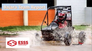
BAJA SAE Brazil Structural Report
1.
2. Introduction
The Bajara Team from the Federal University of the West of Pará,
located in Santarém - Pará - Brazil, carried out simulations of several
situations that could occur, using Ansys software, before the
construction of its off - road vehicle. The general purpose is to
participate in the 22nd SAE Brazil Baja Competition that occured in the
city of São José dos Campos - SP - Brazil. The vehicle's roll cage is the
object of study.
3. The roll cage is the sustaining structure of all vehicle subsystems. It is
also responsible for protecting the pilot's life on specific conditions of
impact. A structure for this purpose shall be deformed and ruptured
before transferring the energy of any loads suffered to the subsystems
or to the pilot.
4. Objectives
Simulate the response of vehicle's roll cage in the following situations:
free body modal analysis; rigid body modal analysis; roll cage's
behavior when it's subjected to frontal and lateral collisions; roll cage's
behavior in rollovers. All of this is necessary to the identification of
sharp or fatigue frequencies at welding points when the vehicle is
traveling on uneven ground or accidents and it is important do
determinate if pilot’s life is protected.
5. Vocabulary
The following vocabulary will be adopted :
Rear Roll Hoop (RRH) ;
Roll Hoop Overhead members (RHO);
Lower Frame Side members (LFS) ;
Front Bracing members (FBM) ;
Lateral Cross Member (LC) or (FLC);
Figure 1: Roll cage tubes.
6. Modelo de análise
Figure 2: Chassis model designed in a computer aided design program (CAD). Figure 3:Real model picture.
7. Figure 4: Details of the geometry used in ANSYS
Figure 5 : Details of the other masses (pilot, engine and steering system) that
are part of the structure.
10. O material do chassi: aço SAE 1020
Name: Steel SAE 1020
Type of model: Isotropic Linear
Flow limit :
𝟑, 𝟓𝟏𝟓𝟕𝟏 ∗ 𝟏𝟎 𝟖
𝑵
𝒎 𝟐
Strength:
𝟒, 𝟐𝟎𝟓𝟎𝟕 ∗ 𝟏𝟎 𝟖
𝑵
𝒎 𝟐
Young’s Modulus:
𝟐 ∗ 𝟏𝟎 𝟖
𝑵
𝒎 𝟐
Poisson’s ratio: 0.29
Specific mass:
𝟕𝟗𝟎𝟎
𝑲𝒈
𝒎 𝟑
Shear modulus:
𝟕, 𝟕 ∗ 𝟏𝟎 𝟏𝟎
𝑵
𝒎 𝟐
Table1:steel pipe’s material.
11. Análise moda de corpo livre
Frequency(Hz)
As the first six frequencies are zero,
Ansys had no trouble recognizing a
geometry.
Figure 8: The first six frequencies are zero in free body modal analysis.
Table 2 :the first Twelve natural frequencies of the structure.
12.
13. Vista geral
Figure 9: six first modes of vibrating with the structure attached to the
suspension system.
Table 3: Six first frequencies of rigid body.
16. Torsional frequency capable of causing fatigue to LFS and USM joints and with greater
intensity and involving more parts of the structure.
Click on the image to animate
17. Torsional frequency capable of causing fatigue to RHO
joints causing fatigue to it's welds. Other regions of the
roll cage also dissipate energy .
Click on the image to animate
18. Torsional frequency capable of causing fatigue to the joints at the
rear of the frame where the engine and fuel tank are fixed. The
energy is also dissipated through RHO.
Click on the image to animate
20. Static structural analysis
This is true for rollover and
collision analysis.
Figure 10: details of static structural analysis.
21. Rollover
The forces applied to the roll cage were calculated with basis on
vehicle's mass and adr59 from the Australian Protocol. The forces used
are: front load; side load; vertical load. All these applied to LC upper
front. The choice of this element is due to this being the least resistant
part of the structure in a possible rollover. The hypothesis adopted for
the value of the forces is based on the speed developed by the vehicle
in the competion conditions. It is possible to deduce the height of jump
force of impact with the ground when the vehicle passes through a
ramp in its maximum speed.
24. The previous figure and the animation above shows the deflections. It is observed in the structure that the maximum deflection
point is in the LC, exact location of application of the rollover frontal force. It is also possible to notice that the deformation is
greater in RHO tubes. The deformations presented are within the safety and comfort limits of 150 mm from SAE and 100 mm
from adr59. The largest deflections are observed in the FBM.
Click on the image to animate
27. The previous figure shows deflections contours. The limits of deflections are within those
recommended by the SAE (150 mm) and adr59 (100 mm). The amplitude of such displacements
begins to cause the application of undesired forces to the pilot, but is not, however, dangerous.
Click on the image to animate
30. The figure shows the deflections contour. The points of greatest deflection are LC and RHO. The range of displacement
shows comfort and absence of danger to the pilot.
Click on the image to animate
31. Collision Forces
The collision forces presented in the model were estimated based on
the linear momentum variation rate. The mass used was the vehicle’s
mass with all its subsystems which is approximately 250 kg. The speed
used was 60 km / h, the maximum speed in which the effects of air
resistance are negligible.
34. This force was estimated when the vehicle is in a straight line and with maximum speed (60 km / h). The figure shows the deflections
contour. The deflection is larger in the Front Bracing Members (FBM) and propagates to the back of the structure decreasing in
amplitude as it progresses. Its maximum value is within the limits of safety and comfort(SAE and adr59).
Click on the image to animate
37. The previous figure and the animation above shows the deflections contour.
Maximum deflections show that the safety limit is not exceeded, but much
of the impact energy will be transmitted to the pilot.
Click on the image to animate
38. Conclusion
The free body and rigid body modal analyzes clearly show that the built structure is subject to
vibrations that can quickly wear out your weld points when the vehicle operates under
required conditions for a long time. This problem will be solved by changing the geometry of
the cage by placing additional tubes to dampen such frequencies.
The collision and rollover assumptions adopted are the worst possible that the team was able
to identify. The simulations show that even in these situations the physical integrity of the
pilot will be protected although the chassis may suffer irreversible damage.
The next steps will gradually transform the vehicle into an agricultural equipment capable of
serving small producers who do not need very large machines, but at the same time can no
longer use hand tools. For this the design requirements will be more robust to be able to
specify a machine that, as in the initial design, is able to walk on extremely rugged terrain
and full of obstacles and can pull heavy loads.
39. Sources
• Ansys Costumer Portal(tutoriais sobre o ANSYS). Available
in<https://support.ansys.com/portal/site/AnsysCustomerPortal>
• Vehicle Standard (Australian Design Rule 59/00 – Standards For
Omnibus Rollover Strength) 2007. Available in: <
https://www.legislation.gov.au/Details/F2012C00535 >
• REGULAMENTO BAJA SAE BRASIL CAPÍTULO 7 REQUISITOS
MÍNIMOS DE SEGURANÇA. Available in: <
http://www.saebrasil.org.br/eventos/ProgramasEstudantis/site/baja2
011/Arquivos/RBSB%207%20-
%20Requisitos%20Minimos%20de%20Seguranca%20-
%20Emenda%202.pdf >