SlideShare a Scribd company logo
1 of 17
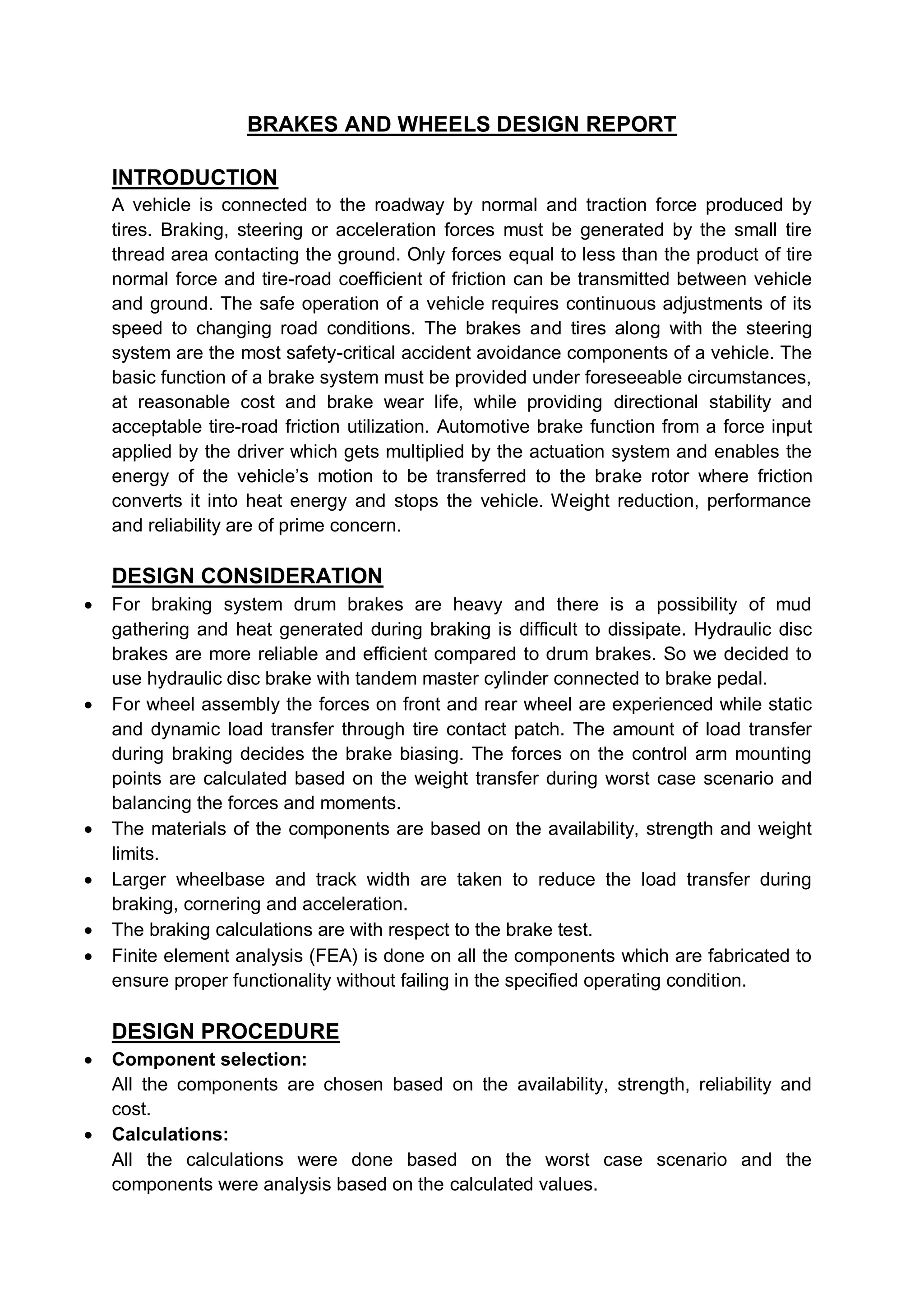
BRAKES AND WHEELS DESIGN REPORT
INTRODUCTION
A vehicle is connected to the roadway by normal and traction force produced by
tires. Braking, steering or acceleration forces must be generated by the small tire
thread area contacting the ground. Only forces equal to less than the product of tire
normal force and tire-road coefficient of friction can be transmitted between vehicle
and ground. The safe operation of a vehicle requires continuous adjustments of its
speed to changing road conditions. The brakes and tires along with the steering
system are the most safety-critical accident avoidance components of a vehicle. The
basic function of a brake system must be provided under foreseeable circumstances,
at reasonable cost and brake wear life, while providing directional stability and
acceptable tire-road friction utilization. Automotive brake function from a force input
applied by the driver which gets multiplied by the actuation system and enables the
energy of the vehicle’s motion to be transferred to the brake rotor where friction
converts it into heat energy and stops the vehicle. Weight reduction, performance
and reliability are of prime concern.
DESIGN CONSIDERATION
 For braking system drum brakes are heavy and there is a possibility of mud
gathering and heat generated during braking is difficult to dissipate. Hydraulic disc
brakes are more reliable and efficient compared to drum brakes. So we decided to
use hydraulic disc brake with tandem master cylinder connected to brake pedal.
 For wheel assembly the forces on front and rear wheel are experienced while static
and dynamic load transfer through tire contact patch. The amount of load transfer
during braking decides the brake biasing. The forces on the control arm mounting
points are calculated based on the weight transfer during worst case scenario and
balancing the forces and moments.
 The materials of the components are based on the availability, strength and weight
limits.
 Larger wheelbase and track width are taken to reduce the load transfer during
braking, cornering and acceleration.
 The braking calculations are with respect to the brake test.
 Finite element analysis (FEA) is done on all the components which are fabricated to
ensure proper functionality without failing in the specified operating condition.
DESIGN PROCEDURE
 Component selection:
All the components are chosen based on the availability, strength, reliability and
cost.
 Calculations:
All the calculations were done based on the worst case scenario and the
components were analysis based on the calculated values.
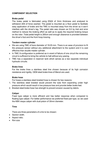
COMPONENT SELECTION
Brake pedal
The brake pedal is fabricated using EN24 of 3mm thickness and analysed to
withstand 2kN of force exerted. The pedal is mounted as a floor pedal to facilitate
easy application of brake and the TMC is mounted away from the driver so it won’t
interfere with the driver’s leg. The pedal ratio was chosen as 5.6 by trial and error
method to reduce the braking effort as well as to apply the required braking torque
on the rotor. Total pedal height is 260cm and enough clearance is provided between
the driver’s foot and the front hoop bracing.
Tandem master cylinder
 We are using TMC of bore diameter of 19.05 mm. There is an ease of provision to fit
the pressure sensor without any additional attachment to the system and it is cost
effective than double master cylinder.
 In TMC X-configuration is preferred as in event of failure of one circuit the remaining
circuit is sufficient to bring the vehicle to halt without any yawing.
 TMC has a separation in reservoir tank which serves as a two separate individual
hydraulic circuits.
Brake lines
For the brake lines a stainless steel line chosen because of its high corrosion
resistance and rigidity. OEM steel brake lines of Maruti are used.
Brake hose
For hoses a stainless steel braided hose is chosen for two reasons:
1. The stainless steel braided would prevent the tube from expanding under high
pressure which would result in low pressure loss and provide better brake feel.
2. Braided steel brake hose has strength to prevent erosion caused by debris.
Caliper
Fixed type caliper is more efficient and has better response when compared to
floating type caliper. For better performance we preferred fixed pair type, so we used
the KBX vespa caliper with dual piston of 30mm diameter.
Tires
There are three parameters of a tire to be chosen:
 Section width.
 Aspect ratio.
 Rim size
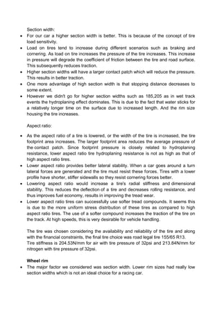
Section width:
 For our car a higher section width is better. This is because of the concept of tire
load sensitivity.
 Load on tires tend to increase during different scenarios such as braking and
cornering. As load on tire increases the pressure of the tire increases. This increase
in pressure will degrade the coefficient of friction between the tire and road surface.
This subsequently reduces traction.
 Higher section widths will have a larger contact patch which will reduce the pressure.
This results in better traction.
 One more advantage of high section width is that stopping distance decreases to
some extent.
 However we didn't go for higher section widths such as 185,205 as in wet track
events the hydroplaning effect dominates. This is due to the fact that water sticks for
a relatively longer time on the surface due to increased length. And the rim size
housing the tire increases.
Aspect ratio:
 As the aspect ratio of a tire is lowered, or the width of the tire is increased, the tire
footprint area increases. The larger footprint area reduces the average pressure of
the contact patch. Since footprint pressure is closely related to hydroplaning
resistance, lower aspect ratio tire hydroplaning resistance is not as high as that of
high aspect ratio tires.
 Lower aspect ratio provides better lateral stability. When a car goes around a turn
lateral forces are generated and the tire must resist these forces. Tires with a lower
profile have shorter, stiffer sidewalls so they resist cornering forces better.
 Lowering aspect ratio would increase a tire's radial stiffness and dimensional
stability. This reduces the deflection of a tire and decreases rolling resistance, and
thus improves fuel economy, results in improving the tread wear.
 Lower aspect ratio tires can successfully use softer tread compounds. It seems this
is due to the more uniform stress distribution of these tires as compared to high
aspect ratio tires. The use of a softer compound increases the traction of the tire on
the track. At high speeds, this is very desirable for vehicle handling.
The tire was chosen considering the availability and reliability of the tire and along
with the financial constraints, the final tire choice was road legal tire 155/65 R13.
Tire stiffness is 204.53N/mm for air with tire pressure of 32psi and 213.84N/mm for
nitrogen with tire pressure of 32psi.
Wheel rim
 The major factor we considered was section width. Lower rim sizes had really low
section widths which is not an ideal choice for a racing car.
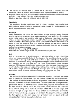
 The 13 inch rim will be able to provide ample clearance for the hub, knuckle
assembly. We could easily fit brake rotors of higher diameters for better braking.
 Negative offsets results in reduction of track and thus higher lateral load transfer and
less grip. So we decided to go with rim with positive offset.
Final rim was fixed to be 5.5J x 13 et30 with 4x100 PCD.
Wheel end
The wheel end is made up of Stub, Hub, Rim, Disc, cylindrical roller bearing and
Knuckle in the sequence. Caliper is mounted on the knuckle. For all four wheels the
entire wheel assembly is press fitted.
.
Bearings
After considering the radial and axial forces on the bearings during different
operational conditions we choose to go with cylindrical roller bearings. It is excellent
under radial loading and good in axial loading. Cylindrical roller bearings were
chosen to meet the required dynamic capacity while reducing the size of the overall
wheel assembly. These bearings are used in pairs in all four wheels to facilitate axial
loads in both the direction. Both front and rear wheels require almost identical
dynamic capacities and hence similar bearings are fitted in front and rear wheels to
reduce the manufacturing cost.
Cylindrical roller bearing: SKF NJ207ECP
OD-72mm, ID-35mm, Length-17mm and Dynamic capacity-56000N
Hub
Hub is the component of wheel assembly in which the wheel is fixed through lug
studs and nuts are used to fasten it. The loads on the wheel (e.g.: bump force) is
experienced on the lug studs and force analysis is done considering worst case
scenario of all the forces during braking and cornering for front hub and acceleration
and cornering for rear hub along with the torque on the wheels. Finite Element
Analysis (FEA) was conducted on the front and rear hubs to ensure the components
would withstand the necessary loads without failing with a material selection Al6061-
T6 to reduce weight and increase strength to weight ratio. The design for front and
rear hubs is similar to reduce the manufacturing and jigging time and cost.
Knuckle
The knuckle connects the steering and suspension systems. It transfers the whole
load of the vehicle to the wheels. Thus, the steering knuckle is a critical component.
The knuckle is mounted to the hub with a cylindrical roller bearing and bolts are
screwed to keep the stud and rotor together. The inner part of the bearing transmits
power from the axle to the wheel. Finite Element Analysis (FEA) was conducted on
the front and rear hubs to ensure the components would withstand the necessary
loads without failing with a material selection Al6061-T6 to reduce weight and
increase strength to weight ratio. The design for front and rear knuckles is similar to
reduce the manufacturing and jigging time and cost. The caliper mounting is fixed at
the front portion of rotor as it would have protection from any debris and heat
dissipation from the rotor is away from the brake pad.
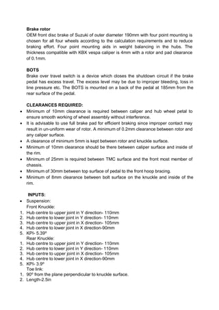
Brake rotor
OEM front disc brake of Suzuki of outer diameter 190mm with four point mounting is
chosen for all four wheels according to the calculation requirements and to reduce
braking effort. Four point mounting aids in weight balancing in the hubs. The
thickness compatible with KBX vespa caliper is 4mm with a rotor and pad clearance
of 0.1mm.
BOTS
Brake over travel switch is a device which closes the shutdown circuit if the brake
pedal has excess travel. The excess level may be due to improper bleeding, loss in
line pressure etc. The BOTS is mounted on a back of the pedal at 185mm from the
rear surface of the pedal.
CLEARANCES REQUIRED:
 Minimum of 10mm clearance is required between caliper and hub wheel petal to
ensure smooth working of wheel assembly without interference.
 It is advisable to use full brake pad for efficient braking since improper contact may
result in un-uniform wear of rotor. A minimum of 0.2mm clearance between rotor and
any caliper surface.
 A clearance of minimum 5mm is kept between rotor and knuckle surface.
 Minimum of 10mm clearance should be there between caliper surface and inside of
the rim.
 Minimum of 25mm is required between TMC surface and the front most member of
chassis.
 Minimum of 30mm between top surface of pedal to the front hoop bracing.
 Minimum of 8mm clearance between bolt surface on the knuckle and inside of the
rim.
INPUTS:
 Suspension:
Front Knuckle:
1. Hub centre to upper joint in Y direction- 110mm
2. Hub centre to lower joint in Y direction- 110mm
3. Hub centre to upper joint in X direction- 105mm
4. Hub centre to lower joint in X direction-90mm
5. KPI- 5.39⁰
Rear Knuckle:
1. Hub centre to upper joint in Y direction- 110mm
2. Hub centre to lower joint in Y direction- 110mm
3. Hub centre to upper joint in X direction- 105mm
4. Hub centre to lower joint in X direction-90mm
5. KPI- 3.9⁰
Toe link:
1. 90⁰ from the plane perpendicular to knuckle surface.
2. Length-2.5in
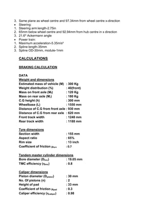
3. Same plane as wheel centre and 97.34mm from wheel centre x-direction
 Steering:
1. Steering arm length-2.75in
2. 65mm below wheel centre and 92.94mm from hub centre in x direction
3. 21.6⁰ Ackermann angle
 Power train:
1. Maximum acceleration-5.35m/s²
2. Spline length-35mm
3. Spline OD-30mm, module-1mm
CALCULATIONS
BRAKING CALCULATION
DATA
Weight and dimensions
Estimated mass of vehicle (M) : 300 Kg
Weight distribution (%) : 40(front)
Mass on front axle (Mf) : 120 Kg
Mass on rear axle (Mr) : 180 Kg
C.G height (h) : 300 mm
Wheelbase (L) : 1550 mm
Distance of C.G from front axle : 930 mm
Distance of C.G from rear axle : 620 mm
Front track width : 1248 mm
Rear track width : 1188 mm
Tyre dimensions
Section width : 155 mm
Aspect ratio : 65%
Rim size : 13 inch
Coefficient of friction µtyre : 0.7
Tandem master cylinder dimensions
Bore diameter (Dtmc) : 19.05 mm
TMC efficiency (ƞtmc) : 0.8
Caliper dimensions
Piston diameter (Dpiston) : 30 mm
No. Of pistons (n) : 2
Height of pad : 33 mm
Coefficient of friction µpad : 0.3
Caliper efficiency (ƞcaliper) : 0.98
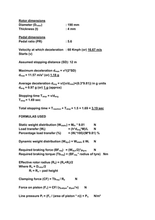
Rotor dimensions
Diameter (Drotor) : 190 mm
Thickness (t) : 4 mm
Pedal dimensions
Pedal ratio (PR) : 5.6
Velocity at which deceleration : 60 Kmph (or) 16.67 m/s
Starts (v)
Assumed stopping distance (SD): 12 m
Maximum deceleration dmax = v²/(2*SD)
dmax = 11.57 m/s² (or) 1.18 g
Average deceleration davg = v/((v/dmax)+(0.3*9.81)) in g units
davg = 0.97 g (or) 1 g (approx)
Stopping time Tstop = v/davg
Tstop = 1.69 sec
Total stopping time = Treaction + Tstop = 1.5 + 1.69 = 3.19 sec
FORMULAS USED
Static weight distribution (Wstatic) = Mf/r * 9.81 N
Load transfer (Wt) = (h*davg*M)/L N
Percentage load transfer (%) = (Wt*100)/(M*9.81) %
Dynamic weight distribution (Wdyn) = Wstatic ± Wt N
Required braking force (BFreq) = (Wdyn/2)*µtyre N
Required braking torque (Tbreq) = (BFreq * radius of tyre) Nm
Effective rotor radius (Re) = (Ro+Ri)/2
Where Ro = Drotor/2
Ri = Ro – pad height
Clamping force (CF) = Tbreq / Re N
Force on piston (Fc) = CF/ (ƞcaliper* µpad*n) N
Line pressure Pl = (Fc / (area of piston * n)) + Po N/m²
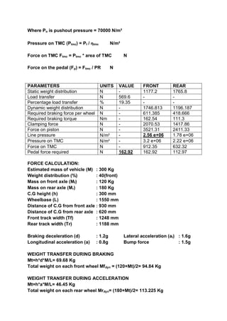
Where Po is pushout pressure = 70000 N/m²
Pressure on TMC (Ptmc) = Pl / ƞtmc N/m²
Force on TMC Ftmc = Ptmc * area of TMC N
Force on the pedal (Fp) = Ftmc / PR N
PARAMETERS UNITS VALUE FRONT REAR
Static weight distribution N - 1177.2 1765.8
Load transfer N 569.6 - -
Percentage load transfer % 19.35 - -
Dynamic weight distribution N - 1746.813 1196.187
Required braking force per wheel N - 611.385 418.666
Required braking torque Nm - 162.54 111.3
Clamping force N - 2070.53 1417.86
Force on piston N - 3521.31 2411.33
Line pressure N/m² - 2.56 e+06 1.78 e+06
Pressure on TMC N/m² - 3.2 e+06 2.22 e+06
Force on TMC N - 912.35 632.32
Pedal force required N 162.92 162.92 112.97
FORCE CALCULATION:
Estimated mass of vehicle (M) : 300 Kg
Weight distribution (%) : 40(front)
Mass on front axle (Mf) : 120 Kg
Mass on rear axle (Mr) : 180 Kg
C.G height (h) : 300 mm
Wheelbase (L) : 1550 mm
Distance of C.G from front axle : 930 mm
Distance of C.G from rear axle : 620 mm
Front track width (Tf) : 1248 mm
Rear track width (Tr) : 1188 mm
Braking deceleration (d) : 1.2g Lateral acceleration (al) : 1.6g
Longitudinal acceleration (a) : 0.8g Bump force : 1.5g
WEIGHT TRANSFER DURING BRAKING
Mt=h*d*M/L= 69.68 Kg
Total weight on each front wheel Mfdyn = (120+Mt)/2= 94.84 Kg
WEIGHT TRANSFER DURING ACCELERATION
Mt=h*a*M/L= 46.45 Kg
Total weight on each rear wheel Mrdyn= (180+Mt)/2= 113.225 Kg
WEIGHT TRANFER DURING CORNERING (FRONT)
Mt=h*al*Mfdyn/Tf = 72.95 Kg
WEIGHT TRANSFER DURING CORNERIG (REAR)
Mt=h*al*Mrdyn/Tr = 91.5 Kg
Net weight on front outer tyre= 167.79 Kg
Net weight on rear outer tyre= 204.72 Kg
CONTACT PATCH FORCES
Front Rear
Ftx= 1975.24 N 1606.65 N
Fty= 2633.66 N 3213.31 N
Ftz= 2469.05 N 3012.48 N
Solving the forces and moments in side view yields the longitudinal forces and
solving the forces and moments in front view yields the lateral forces on the upper
and lower control arm mounting points. The vertical force on the mounting points is
taken as the bump force in the contact patch.
The force on the hub is same as the tire contact patch forces acting at the rolling
radius.
Forces on knuckle and hub:
Component Fx(N) Fy(N) Fz(N) T(Nm)
KNUCKLE
FRONT
Upper joint 1399.38 855.64 2469.05 -
Lower joint 3374.52 3489.4 2469.05 -
Caliper mount - - - 266.55
Steering arm - 1000 200 -
REAR
Upper joint 1138.17 1043.96 3012.48 -
Lower joint 2744.82 4257.27 3012.48 -
Caliper mount - - - 266.55
Toe link - 800 200 -
HUB
FRONT
Wheel mount 1975.24 2633.66 2469.05 -
Rotor mount - - - 266.55
REAR
Wheel mount 1606.65 3213.31 3012.48 -
Rotor mount - - - 266.55
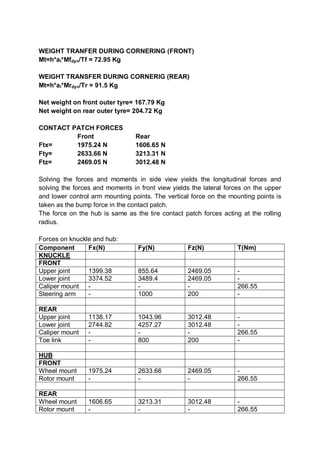
BEARING DYNAMIC LOAD CALCULATION
Dynamic load Dynamic capacity
The life of the bearing was assumed to be 54 million revolutions
After calculating the dynamic load for front and rear wheels we arrived to the
required dynamic capacity.
Required Dynamic capacity (front wheel) = 44236.56N
Required Dynamic capacity (rear wheel) = 47906.91N
MODEL AND ANALYSIS
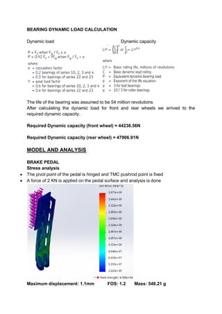
BRAKE PEDAL
Stress analysis
 The pivot point of the pedal is hinged and TMC pushrod point is fixed
 A force of 2 KN is applied on the pedal surface and analysis is done
Maximum displacement: 1.1mm FOS: 1.2 Mass: 548.21 g
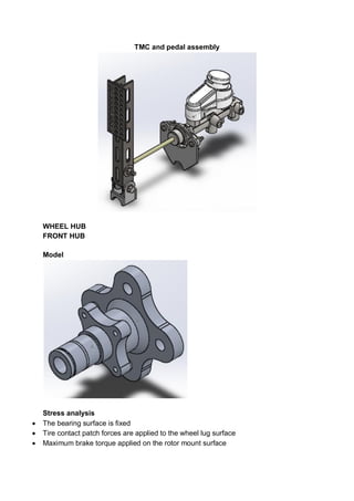
TMC and pedal assembly
WHEEL HUB
FRONT HUB
Model
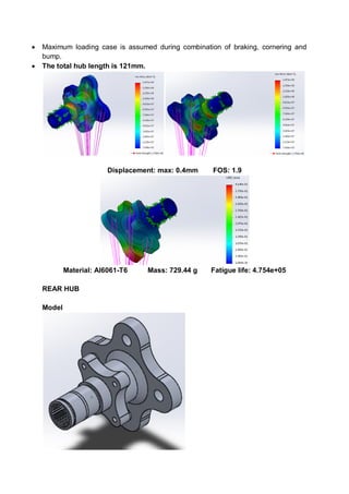
Stress analysis
 The bearing surface is fixed
 Tire contact patch forces are applied to the wheel lug surface
 Maximum brake torque applied on the rotor mount surface
 Maximum loading case is assumed during combination of braking, cornering and
bump.
 The total hub length is 121mm.
Displacement: max: 0.4mm FOS: 1.9
Material: Al6061-T6 Mass: 729.44 g Fatigue life: 4.754e+05
REAR HUB
Model
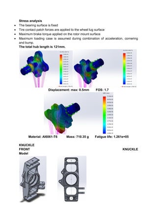
Stress analysis
 The bearing surface is fixed
 Tire contact patch forces are applied to the wheel lug surface
 Maximum brake torque applied on the rotor mount surface
 Maximum loading case is assumed during combination of acceleration, cornering
and bump.
The total hub length is 121mm.
Displacement: max: 0.5mm FOS: 1.7
Material: Al6061-T6 Mass: 710.35 g Fatigue life: 1.261e+05
KNUCKLE
FRONT KNUCKLE
Model
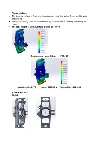
Stress analysis
 The bearing surface is fixed and the calculated mounting points forces and torques
are applied.
 Maximum loading case is assumed during combination of braking, cornering and
bump.
 The total height of the knuckle is 256mm or 10.07in
Displacement: max: 0.4mm FOS: 2.2
Material: Al6061-T6 Mass: 1093.42 g Fatigue life: 1.982 e+06
REAR KNUCKLE
Model
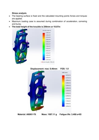
Stress analysis
 The bearing surface is fixed and the calculated mounting points forces and torques
are applied.
 Maximum loading case is assumed during combination of acceleration, cornering
and bump.
 The total height of the knuckle is 256mm or 10.07in
Displacement: max: 0.46mm FOS: 1.9
Material: Al6061-T6 Mass: 1087.11 g Fatigue life: 3.468 e+05
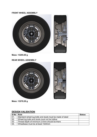
FRONT WHEEL ASSEMBLY
Mass: 13295.69 g
REAR WHEEL ASSEMBLY
Mass: 13270.28 g
DESIGN VALIDATION
S.No Rule Status
01. Standard wheel lug bolts and studs must be made of steel
02. Wheel lug bolts and studs must not be hollow
03. Thread depth of minimum 2.4mm should be there
04. Wheelbase must be at least 1525mm
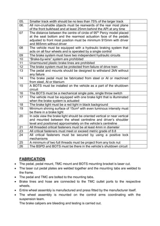
05. Smaller track width should be no less than 75% of the larger track
06. All non-crushable objects must be rearwards of the rear most plane
of the front bulkhead and at least 25mm behind the API at any time
07 The distance between the centre of circle of 95th
Percy model placed
at the seat bottom and the rearmost actuation face of the pedals
adjusted to front most position must be minimum 915mm with driver
and 865mm without driver
08 The vehicle must be equipped with a hydraulic braking system that
acts on all four wheels and is operated by a single control
09 The brake system must have two independent hydraulic circuits
10 “Brake-by-wire” system are prohibited
11 Unarmoured plastic brake lines are prohibited
12 The brake system must be protected from failure of drive train
13 The pedal and mounts should be designed to withstand 2kN without
any failure
14 The brake pedal must be fabricated from steel or Al or machined
from steel, Al or titanium
15 A BOTS must be installed on the vehicle as a part of the shutdown
circuit
16 The BOTS must be a mechanical single pole, single throw switch
17 The vehicle must be equipped with one brake light that is illuminated
when the brake system is actuated
18 The brake light must be a red light in black background
19 Minimum shining surface of 15cm² with even luminous intensity must
be there in a brake light
20 In side view the brake light should be oriented vertical or near vertical
and mounted between the wheel centreline and driver’s shoulder
level and positioned approximately on the vehicle’s centreline
21 All threaded critical fasteners must be at least 4mm in diameter
23 All critical fasteners must meet or exceed metric grade of 8.8
24 All critical fasteners must be secured by using a positive lock
mechanisms
25 A minimum of two full threads must be project from any lock nut
26 The BSPD and BOTS must be there in the vehicle’s shutdown circuit
FABRICATION
 The pedal, pedal mount, TMC mount and BOTS mounting bracket is laser cut.
 The laser cut pedal plates are welded together and the mounting tabs are welded to
the frame.
 The pedal and TMC are bolted to the mounting tabs.
 Brake lines and hose are connected to the TMC outlet ports to the respective
wheels.
 Entire wheel assembly is manufactured and press fitted by the manufacturer itself.
 The wheel assembly is mounted on the control arms coordinating with the
suspension team.
The brake calipers are bleeding and testing is carried out.

More Related Content

Similar to Brake and Wheels Design Report 3rd iteration.pdf

IRJET-Design & Fabrication of Rear Outboard Wheel Assembly for an ATV
IRJET-Design & Fabrication of Rear Outboard Wheel Assembly for an ATVIRJET-Design & Fabrication of Rear Outboard Wheel Assembly for an ATV
IRJET-Design & Fabrication of Rear Outboard Wheel Assembly for an ATVIRJET Journal
 
Design of Bevel Gears for Automotive Differentials and a Brief Study
Design of Bevel Gears for Automotive Differentials and a Brief StudyDesign of Bevel Gears for Automotive Differentials and a Brief Study
Design of Bevel Gears for Automotive Differentials and a Brief StudyIRJET Journal
 
Baja sae india suspension design
Baja sae india suspension designBaja sae india suspension design
Baja sae india suspension designUpender Rawat
 
Paper id 312201529
Paper id 312201529Paper id 312201529
Paper id 312201529IJRAT
 
The International Journal of Engineering and Science (The IJES)
The International Journal of Engineering and Science (The IJES)The International Journal of Engineering and Science (The IJES)
The International Journal of Engineering and Science (The IJES)theijes
 
Mech disc brakes ppt
Mech disc brakes  pptMech disc brakes  ppt
Mech disc brakes pptrockboy1999
 
Tyres used in agricultural implements
Tyres used in agricultural implementsTyres used in agricultural implements
Tyres used in agricultural implementsAmit Namdeo
 
IRJET-Design of Brake Disc for Hydraulic Brakes
IRJET-Design of Brake Disc for Hydraulic BrakesIRJET-Design of Brake Disc for Hydraulic Brakes
IRJET-Design of Brake Disc for Hydraulic BrakesIRJET Journal
 
mech Disc brakes ppt.pptx
mech Disc brakes  ppt.pptxmech Disc brakes  ppt.pptx
mech Disc brakes ppt.pptxrajmohonsarkar
 
BRAKES PPT.........................................
BRAKES PPT.........................................BRAKES PPT.........................................
BRAKES PPT.........................................ayushambadare99
 
Eckstein, Nathan Resume Portfolio Doc
Eckstein, Nathan Resume Portfolio DocEckstein, Nathan Resume Portfolio Doc
Eckstein, Nathan Resume Portfolio DocNathan Eckstein
 
IRJET - Design and Analysis of Double Wishbone Suspension for Formula Student...
IRJET - Design and Analysis of Double Wishbone Suspension for Formula Student...IRJET - Design and Analysis of Double Wishbone Suspension for Formula Student...
IRJET - Design and Analysis of Double Wishbone Suspension for Formula Student...IRJET Journal
 
LOW PROFILE TIRE IMPACT ON DOUBLE WISHBONE SUSPENSION
LOW PROFILE TIRE IMPACT ON DOUBLE WISHBONE SUSPENSIONLOW PROFILE TIRE IMPACT ON DOUBLE WISHBONE SUSPENSION
LOW PROFILE TIRE IMPACT ON DOUBLE WISHBONE SUSPENSIONijiert bestjournal
 

Similar to Brake and Wheels Design Report 3rd iteration.pdf (20)

IRJET-Design & Fabrication of Rear Outboard Wheel Assembly for an ATV
IRJET-Design & Fabrication of Rear Outboard Wheel Assembly for an ATVIRJET-Design & Fabrication of Rear Outboard Wheel Assembly for an ATV
IRJET-Design & Fabrication of Rear Outboard Wheel Assembly for an ATV
 
K012447075
K012447075K012447075
K012447075
 
Design of Bevel Gears for Automotive Differentials and a Brief Study
Design of Bevel Gears for Automotive Differentials and a Brief StudyDesign of Bevel Gears for Automotive Differentials and a Brief Study
Design of Bevel Gears for Automotive Differentials and a Brief Study
 
Tyres Baja
Tyres  BajaTyres  Baja
Tyres Baja
 
Baja sae india suspension design
Baja sae india suspension designBaja sae india suspension design
Baja sae india suspension design
 
5800643.ppt
5800643.ppt5800643.ppt
5800643.ppt
 
Paper id 312201529
Paper id 312201529Paper id 312201529
Paper id 312201529
 
The International Journal of Engineering and Science (The IJES)
The International Journal of Engineering and Science (The IJES)The International Journal of Engineering and Science (The IJES)
The International Journal of Engineering and Science (The IJES)
 
Mech disc brakes ppt
Mech disc brakes  pptMech disc brakes  ppt
Mech disc brakes ppt
 
Tyres used in agricultural implements
Tyres used in agricultural implementsTyres used in agricultural implements
Tyres used in agricultural implements
 
IRJET-Design of Brake Disc for Hydraulic Brakes
IRJET-Design of Brake Disc for Hydraulic BrakesIRJET-Design of Brake Disc for Hydraulic Brakes
IRJET-Design of Brake Disc for Hydraulic Brakes
 
mech Disc brakes ppt.pptx
mech Disc brakes  ppt.pptxmech Disc brakes  ppt.pptx
mech Disc brakes ppt.pptx
 
Pavan ppt
Pavan pptPavan ppt
Pavan ppt
 
[IJET V2I5P11] Authors: P. R. SHINDE , Dr. K. B. KALE
[IJET V2I5P11] Authors: P. R. SHINDE , Dr. K. B. KALE[IJET V2I5P11] Authors: P. R. SHINDE , Dr. K. B. KALE
[IJET V2I5P11] Authors: P. R. SHINDE , Dr. K. B. KALE
 
BRAKES PPT.........................................
BRAKES PPT.........................................BRAKES PPT.........................................
BRAKES PPT.........................................
 
Tyres wheels1
Tyres wheels1Tyres wheels1
Tyres wheels1
 
Eckstein, Nathan Resume Portfolio Doc
Eckstein, Nathan Resume Portfolio DocEckstein, Nathan Resume Portfolio Doc
Eckstein, Nathan Resume Portfolio Doc
 
IRJET - Design and Analysis of Double Wishbone Suspension for Formula Student...
IRJET - Design and Analysis of Double Wishbone Suspension for Formula Student...IRJET - Design and Analysis of Double Wishbone Suspension for Formula Student...
IRJET - Design and Analysis of Double Wishbone Suspension for Formula Student...
 
Rolling Resistance.pptx
Rolling Resistance.pptxRolling Resistance.pptx
Rolling Resistance.pptx
 
LOW PROFILE TIRE IMPACT ON DOUBLE WISHBONE SUSPENSION
LOW PROFILE TIRE IMPACT ON DOUBLE WISHBONE SUSPENSIONLOW PROFILE TIRE IMPACT ON DOUBLE WISHBONE SUSPENSION
LOW PROFILE TIRE IMPACT ON DOUBLE WISHBONE SUSPENSION
 

Recently uploaded

VIP Call Girls Bhiwandi Ananya 8250192130 Independent Escort Service Bhiwandi
VIP Call Girls Bhiwandi Ananya 8250192130 Independent Escort Service BhiwandiVIP Call Girls Bhiwandi Ananya 8250192130 Independent Escort Service Bhiwandi
VIP Call Girls Bhiwandi Ananya 8250192130 Independent Escort Service BhiwandiSuhani Kapoor
 
VIP Russian Call Girls in Saharanpur Deepika 8250192130 Independent Escort Se...
VIP Russian Call Girls in Saharanpur Deepika 8250192130 Independent Escort Se...VIP Russian Call Girls in Saharanpur Deepika 8250192130 Independent Escort Se...
VIP Russian Call Girls in Saharanpur Deepika 8250192130 Independent Escort Se...Suhani Kapoor
 
VIP Call Girls Service Bhagyanagar Hyderabad Call +91-8250192130
VIP Call Girls Service Bhagyanagar Hyderabad Call +91-8250192130VIP Call Girls Service Bhagyanagar Hyderabad Call +91-8250192130
VIP Call Girls Service Bhagyanagar Hyderabad Call +91-8250192130Suhani Kapoor
 
Call Girls In Safdarjung Enclave 24/7✡️9711147426✡️ Escorts Service
Call Girls In Safdarjung Enclave 24/7✡️9711147426✡️ Escorts ServiceCall Girls In Safdarjung Enclave 24/7✡️9711147426✡️ Escorts Service
Call Girls In Safdarjung Enclave 24/7✡️9711147426✡️ Escorts Servicejennyeacort
 
call girls in Harsh Vihar (DELHI) 🔝 >༒9953330565🔝 genuine Escort Service 🔝✔️✔️
call girls in Harsh Vihar (DELHI) 🔝 >༒9953330565🔝 genuine Escort Service 🔝✔️✔️call girls in Harsh Vihar (DELHI) 🔝 >༒9953330565🔝 genuine Escort Service 🔝✔️✔️
call girls in Harsh Vihar (DELHI) 🔝 >༒9953330565🔝 genuine Escort Service 🔝✔️✔️9953056974 Low Rate Call Girls In Saket, Delhi NCR
 
WAEC Carpentry and Joinery Past Questions
WAEC Carpentry and Joinery Past QuestionsWAEC Carpentry and Joinery Past Questions
WAEC Carpentry and Joinery Past QuestionsCharles Obaleagbon
 
CALL ON ➥8923113531 🔝Call Girls Aminabad Lucknow best Night Fun service
CALL ON ➥8923113531 🔝Call Girls Aminabad Lucknow best Night Fun serviceCALL ON ➥8923113531 🔝Call Girls Aminabad Lucknow best Night Fun service
CALL ON ➥8923113531 🔝Call Girls Aminabad Lucknow best Night Fun serviceanilsa9823
 
NO1 Famous Amil Baba In Karachi Kala Jadu In Karachi Amil baba In Karachi Add...
NO1 Famous Amil Baba In Karachi Kala Jadu In Karachi Amil baba In Karachi Add...NO1 Famous Amil Baba In Karachi Kala Jadu In Karachi Amil baba In Karachi Add...
NO1 Famous Amil Baba In Karachi Kala Jadu In Karachi Amil baba In Karachi Add...Amil baba
 
VIP Kolkata Call Girl Gariahat 👉 8250192130 Available With Room
VIP Kolkata Call Girl Gariahat 👉 8250192130  Available With RoomVIP Kolkata Call Girl Gariahat 👉 8250192130  Available With Room
VIP Kolkata Call Girl Gariahat 👉 8250192130 Available With Roomdivyansh0kumar0
 
SCRIP Lua HTTP PROGRACMACION PLC WECON CA
SCRIP Lua HTTP PROGRACMACION PLC  WECON CASCRIP Lua HTTP PROGRACMACION PLC  WECON CA
SCRIP Lua HTTP PROGRACMACION PLC WECON CANestorGamez6
 
Raj Nagar Extension Call Girls 9711199012 WhatsApp No, Delhi Escorts in Raj N...
Raj Nagar Extension Call Girls 9711199012 WhatsApp No, Delhi Escorts in Raj N...Raj Nagar Extension Call Girls 9711199012 WhatsApp No, Delhi Escorts in Raj N...
Raj Nagar Extension Call Girls 9711199012 WhatsApp No, Delhi Escorts in Raj N...ankitnayak356677
 
Best VIP Call Girls Noida Sector 44 Call Me: 8448380779
Best VIP Call Girls Noida Sector 44 Call Me: 8448380779Best VIP Call Girls Noida Sector 44 Call Me: 8448380779
Best VIP Call Girls Noida Sector 44 Call Me: 8448380779Delhi Call girls
 
The history of music videos a level presentation
The history of music videos a level presentationThe history of music videos a level presentation
The history of music videos a level presentationamedia6
 
VIP College Call Girls Gorakhpur Bhavna 8250192130 Independent Escort Service...
VIP College Call Girls Gorakhpur Bhavna 8250192130 Independent Escort Service...VIP College Call Girls Gorakhpur Bhavna 8250192130 Independent Escort Service...
VIP College Call Girls Gorakhpur Bhavna 8250192130 Independent Escort Service...Suhani Kapoor
 
Abu Dhabi Call Girls O58993O4O2 Call Girls in Abu Dhabi`
Abu Dhabi Call Girls O58993O4O2 Call Girls in Abu Dhabi`Abu Dhabi Call Girls O58993O4O2 Call Girls in Abu Dhabi`
Abu Dhabi Call Girls O58993O4O2 Call Girls in Abu Dhabi`dajasot375
 
The_Canvas_of_Creative_Mastery_Newsletter_April_2024_Version.pdf
The_Canvas_of_Creative_Mastery_Newsletter_April_2024_Version.pdfThe_Canvas_of_Creative_Mastery_Newsletter_April_2024_Version.pdf
The_Canvas_of_Creative_Mastery_Newsletter_April_2024_Version.pdfAmirYakdi
 
VIP Call Girls Service Mehdipatnam Hyderabad Call +91-8250192130
VIP Call Girls Service Mehdipatnam Hyderabad Call +91-8250192130VIP Call Girls Service Mehdipatnam Hyderabad Call +91-8250192130
VIP Call Girls Service Mehdipatnam Hyderabad Call +91-8250192130Suhani Kapoor
 
Cheap Rate ➥8448380779 ▻Call Girls In Iffco Chowk Gurgaon
Cheap Rate ➥8448380779 ▻Call Girls In Iffco Chowk GurgaonCheap Rate ➥8448380779 ▻Call Girls In Iffco Chowk Gurgaon
Cheap Rate ➥8448380779 ▻Call Girls In Iffco Chowk GurgaonDelhi Call girls
 
PODSCAPE - Brochure 2023_ prefab homes in Bangalore India
PODSCAPE - Brochure 2023_ prefab homes in Bangalore IndiaPODSCAPE - Brochure 2023_ prefab homes in Bangalore India
PODSCAPE - Brochure 2023_ prefab homes in Bangalore IndiaYathish29
 

Recently uploaded (20)

VIP Call Girls Bhiwandi Ananya 8250192130 Independent Escort Service Bhiwandi
VIP Call Girls Bhiwandi Ananya 8250192130 Independent Escort Service BhiwandiVIP Call Girls Bhiwandi Ananya 8250192130 Independent Escort Service Bhiwandi
VIP Call Girls Bhiwandi Ananya 8250192130 Independent Escort Service Bhiwandi
 
VIP Russian Call Girls in Saharanpur Deepika 8250192130 Independent Escort Se...
VIP Russian Call Girls in Saharanpur Deepika 8250192130 Independent Escort Se...VIP Russian Call Girls in Saharanpur Deepika 8250192130 Independent Escort Se...
VIP Russian Call Girls in Saharanpur Deepika 8250192130 Independent Escort Se...
 
VIP Call Girls Service Bhagyanagar Hyderabad Call +91-8250192130
VIP Call Girls Service Bhagyanagar Hyderabad Call +91-8250192130VIP Call Girls Service Bhagyanagar Hyderabad Call +91-8250192130
VIP Call Girls Service Bhagyanagar Hyderabad Call +91-8250192130
 
Call Girls In Safdarjung Enclave 24/7✡️9711147426✡️ Escorts Service
Call Girls In Safdarjung Enclave 24/7✡️9711147426✡️ Escorts ServiceCall Girls In Safdarjung Enclave 24/7✡️9711147426✡️ Escorts Service
Call Girls In Safdarjung Enclave 24/7✡️9711147426✡️ Escorts Service
 
call girls in Harsh Vihar (DELHI) 🔝 >༒9953330565🔝 genuine Escort Service 🔝✔️✔️
call girls in Harsh Vihar (DELHI) 🔝 >༒9953330565🔝 genuine Escort Service 🔝✔️✔️call girls in Harsh Vihar (DELHI) 🔝 >༒9953330565🔝 genuine Escort Service 🔝✔️✔️
call girls in Harsh Vihar (DELHI) 🔝 >༒9953330565🔝 genuine Escort Service 🔝✔️✔️
 
WAEC Carpentry and Joinery Past Questions
WAEC Carpentry and Joinery Past QuestionsWAEC Carpentry and Joinery Past Questions
WAEC Carpentry and Joinery Past Questions
 
CALL ON ➥8923113531 🔝Call Girls Aminabad Lucknow best Night Fun service
CALL ON ➥8923113531 🔝Call Girls Aminabad Lucknow best Night Fun serviceCALL ON ➥8923113531 🔝Call Girls Aminabad Lucknow best Night Fun service
CALL ON ➥8923113531 🔝Call Girls Aminabad Lucknow best Night Fun service
 
NO1 Famous Amil Baba In Karachi Kala Jadu In Karachi Amil baba In Karachi Add...
NO1 Famous Amil Baba In Karachi Kala Jadu In Karachi Amil baba In Karachi Add...NO1 Famous Amil Baba In Karachi Kala Jadu In Karachi Amil baba In Karachi Add...
NO1 Famous Amil Baba In Karachi Kala Jadu In Karachi Amil baba In Karachi Add...
 
VIP Kolkata Call Girl Gariahat 👉 8250192130 Available With Room
VIP Kolkata Call Girl Gariahat 👉 8250192130  Available With RoomVIP Kolkata Call Girl Gariahat 👉 8250192130  Available With Room
VIP Kolkata Call Girl Gariahat 👉 8250192130 Available With Room
 
SCRIP Lua HTTP PROGRACMACION PLC WECON CA
SCRIP Lua HTTP PROGRACMACION PLC  WECON CASCRIP Lua HTTP PROGRACMACION PLC  WECON CA
SCRIP Lua HTTP PROGRACMACION PLC WECON CA
 
Raj Nagar Extension Call Girls 9711199012 WhatsApp No, Delhi Escorts in Raj N...
Raj Nagar Extension Call Girls 9711199012 WhatsApp No, Delhi Escorts in Raj N...Raj Nagar Extension Call Girls 9711199012 WhatsApp No, Delhi Escorts in Raj N...
Raj Nagar Extension Call Girls 9711199012 WhatsApp No, Delhi Escorts in Raj N...
 
Best VIP Call Girls Noida Sector 44 Call Me: 8448380779
Best VIP Call Girls Noida Sector 44 Call Me: 8448380779Best VIP Call Girls Noida Sector 44 Call Me: 8448380779
Best VIP Call Girls Noida Sector 44 Call Me: 8448380779
 
The history of music videos a level presentation
The history of music videos a level presentationThe history of music videos a level presentation
The history of music videos a level presentation
 
VIP College Call Girls Gorakhpur Bhavna 8250192130 Independent Escort Service...
VIP College Call Girls Gorakhpur Bhavna 8250192130 Independent Escort Service...VIP College Call Girls Gorakhpur Bhavna 8250192130 Independent Escort Service...
VIP College Call Girls Gorakhpur Bhavna 8250192130 Independent Escort Service...
 
Abu Dhabi Call Girls O58993O4O2 Call Girls in Abu Dhabi`
Abu Dhabi Call Girls O58993O4O2 Call Girls in Abu Dhabi`Abu Dhabi Call Girls O58993O4O2 Call Girls in Abu Dhabi`
Abu Dhabi Call Girls O58993O4O2 Call Girls in Abu Dhabi`
 
The_Canvas_of_Creative_Mastery_Newsletter_April_2024_Version.pdf
The_Canvas_of_Creative_Mastery_Newsletter_April_2024_Version.pdfThe_Canvas_of_Creative_Mastery_Newsletter_April_2024_Version.pdf
The_Canvas_of_Creative_Mastery_Newsletter_April_2024_Version.pdf
 
VIP Call Girls Service Mehdipatnam Hyderabad Call +91-8250192130
VIP Call Girls Service Mehdipatnam Hyderabad Call +91-8250192130VIP Call Girls Service Mehdipatnam Hyderabad Call +91-8250192130
VIP Call Girls Service Mehdipatnam Hyderabad Call +91-8250192130
 
Cheap Rate ➥8448380779 ▻Call Girls In Iffco Chowk Gurgaon
Cheap Rate ➥8448380779 ▻Call Girls In Iffco Chowk GurgaonCheap Rate ➥8448380779 ▻Call Girls In Iffco Chowk Gurgaon
Cheap Rate ➥8448380779 ▻Call Girls In Iffco Chowk Gurgaon
 
young call girls in Vivek Vihar🔝 9953056974 🔝 Delhi escort Service
young call girls in Vivek Vihar🔝 9953056974 🔝 Delhi escort Serviceyoung call girls in Vivek Vihar🔝 9953056974 🔝 Delhi escort Service
young call girls in Vivek Vihar🔝 9953056974 🔝 Delhi escort Service
 
PODSCAPE - Brochure 2023_ prefab homes in Bangalore India
PODSCAPE - Brochure 2023_ prefab homes in Bangalore IndiaPODSCAPE - Brochure 2023_ prefab homes in Bangalore India
PODSCAPE - Brochure 2023_ prefab homes in Bangalore India
 

Brake and Wheels Design Report 3rd iteration.pdf

  • 1. BRAKES AND WHEELS DESIGN REPORT INTRODUCTION A vehicle is connected to the roadway by normal and traction force produced by tires. Braking, steering or acceleration forces must be generated by the small tire thread area contacting the ground. Only forces equal to less than the product of tire normal force and tire-road coefficient of friction can be transmitted between vehicle and ground. The safe operation of a vehicle requires continuous adjustments of its speed to changing road conditions. The brakes and tires along with the steering system are the most safety-critical accident avoidance components of a vehicle. The basic function of a brake system must be provided under foreseeable circumstances, at reasonable cost and brake wear life, while providing directional stability and acceptable tire-road friction utilization. Automotive brake function from a force input applied by the driver which gets multiplied by the actuation system and enables the energy of the vehicle’s motion to be transferred to the brake rotor where friction converts it into heat energy and stops the vehicle. Weight reduction, performance and reliability are of prime concern. DESIGN CONSIDERATION  For braking system drum brakes are heavy and there is a possibility of mud gathering and heat generated during braking is difficult to dissipate. Hydraulic disc brakes are more reliable and efficient compared to drum brakes. So we decided to use hydraulic disc brake with tandem master cylinder connected to brake pedal.  For wheel assembly the forces on front and rear wheel are experienced while static and dynamic load transfer through tire contact patch. The amount of load transfer during braking decides the brake biasing. The forces on the control arm mounting points are calculated based on the weight transfer during worst case scenario and balancing the forces and moments.  The materials of the components are based on the availability, strength and weight limits.  Larger wheelbase and track width are taken to reduce the load transfer during braking, cornering and acceleration.  The braking calculations are with respect to the brake test.  Finite element analysis (FEA) is done on all the components which are fabricated to ensure proper functionality without failing in the specified operating condition. DESIGN PROCEDURE  Component selection: All the components are chosen based on the availability, strength, reliability and cost.  Calculations: All the calculations were done based on the worst case scenario and the components were analysis based on the calculated values.
  • 2. COMPONENT SELECTION Brake pedal The brake pedal is fabricated using EN24 of 3mm thickness and analysed to withstand 2kN of force exerted. The pedal is mounted as a floor pedal to facilitate easy application of brake and the TMC is mounted away from the driver so it won’t interfere with the driver’s leg. The pedal ratio was chosen as 5.6 by trial and error method to reduce the braking effort as well as to apply the required braking torque on the rotor. Total pedal height is 260cm and enough clearance is provided between the driver’s foot and the front hoop bracing. Tandem master cylinder  We are using TMC of bore diameter of 19.05 mm. There is an ease of provision to fit the pressure sensor without any additional attachment to the system and it is cost effective than double master cylinder.  In TMC X-configuration is preferred as in event of failure of one circuit the remaining circuit is sufficient to bring the vehicle to halt without any yawing.  TMC has a separation in reservoir tank which serves as a two separate individual hydraulic circuits. Brake lines For the brake lines a stainless steel line chosen because of its high corrosion resistance and rigidity. OEM steel brake lines of Maruti are used. Brake hose For hoses a stainless steel braided hose is chosen for two reasons: 1. The stainless steel braided would prevent the tube from expanding under high pressure which would result in low pressure loss and provide better brake feel. 2. Braided steel brake hose has strength to prevent erosion caused by debris. Caliper Fixed type caliper is more efficient and has better response when compared to floating type caliper. For better performance we preferred fixed pair type, so we used the KBX vespa caliper with dual piston of 30mm diameter. Tires There are three parameters of a tire to be chosen:  Section width.  Aspect ratio.  Rim size
  • 3. Section width:  For our car a higher section width is better. This is because of the concept of tire load sensitivity.  Load on tires tend to increase during different scenarios such as braking and cornering. As load on tire increases the pressure of the tire increases. This increase in pressure will degrade the coefficient of friction between the tire and road surface. This subsequently reduces traction.  Higher section widths will have a larger contact patch which will reduce the pressure. This results in better traction.  One more advantage of high section width is that stopping distance decreases to some extent.  However we didn't go for higher section widths such as 185,205 as in wet track events the hydroplaning effect dominates. This is due to the fact that water sticks for a relatively longer time on the surface due to increased length. And the rim size housing the tire increases. Aspect ratio:  As the aspect ratio of a tire is lowered, or the width of the tire is increased, the tire footprint area increases. The larger footprint area reduces the average pressure of the contact patch. Since footprint pressure is closely related to hydroplaning resistance, lower aspect ratio tire hydroplaning resistance is not as high as that of high aspect ratio tires.  Lower aspect ratio provides better lateral stability. When a car goes around a turn lateral forces are generated and the tire must resist these forces. Tires with a lower profile have shorter, stiffer sidewalls so they resist cornering forces better.  Lowering aspect ratio would increase a tire's radial stiffness and dimensional stability. This reduces the deflection of a tire and decreases rolling resistance, and thus improves fuel economy, results in improving the tread wear.  Lower aspect ratio tires can successfully use softer tread compounds. It seems this is due to the more uniform stress distribution of these tires as compared to high aspect ratio tires. The use of a softer compound increases the traction of the tire on the track. At high speeds, this is very desirable for vehicle handling. The tire was chosen considering the availability and reliability of the tire and along with the financial constraints, the final tire choice was road legal tire 155/65 R13. Tire stiffness is 204.53N/mm for air with tire pressure of 32psi and 213.84N/mm for nitrogen with tire pressure of 32psi. Wheel rim  The major factor we considered was section width. Lower rim sizes had really low section widths which is not an ideal choice for a racing car.
  • 4.  The 13 inch rim will be able to provide ample clearance for the hub, knuckle assembly. We could easily fit brake rotors of higher diameters for better braking.  Negative offsets results in reduction of track and thus higher lateral load transfer and less grip. So we decided to go with rim with positive offset. Final rim was fixed to be 5.5J x 13 et30 with 4x100 PCD. Wheel end The wheel end is made up of Stub, Hub, Rim, Disc, cylindrical roller bearing and Knuckle in the sequence. Caliper is mounted on the knuckle. For all four wheels the entire wheel assembly is press fitted. . Bearings After considering the radial and axial forces on the bearings during different operational conditions we choose to go with cylindrical roller bearings. It is excellent under radial loading and good in axial loading. Cylindrical roller bearings were chosen to meet the required dynamic capacity while reducing the size of the overall wheel assembly. These bearings are used in pairs in all four wheels to facilitate axial loads in both the direction. Both front and rear wheels require almost identical dynamic capacities and hence similar bearings are fitted in front and rear wheels to reduce the manufacturing cost. Cylindrical roller bearing: SKF NJ207ECP OD-72mm, ID-35mm, Length-17mm and Dynamic capacity-56000N Hub Hub is the component of wheel assembly in which the wheel is fixed through lug studs and nuts are used to fasten it. The loads on the wheel (e.g.: bump force) is experienced on the lug studs and force analysis is done considering worst case scenario of all the forces during braking and cornering for front hub and acceleration and cornering for rear hub along with the torque on the wheels. Finite Element Analysis (FEA) was conducted on the front and rear hubs to ensure the components would withstand the necessary loads without failing with a material selection Al6061- T6 to reduce weight and increase strength to weight ratio. The design for front and rear hubs is similar to reduce the manufacturing and jigging time and cost. Knuckle The knuckle connects the steering and suspension systems. It transfers the whole load of the vehicle to the wheels. Thus, the steering knuckle is a critical component. The knuckle is mounted to the hub with a cylindrical roller bearing and bolts are screwed to keep the stud and rotor together. The inner part of the bearing transmits power from the axle to the wheel. Finite Element Analysis (FEA) was conducted on the front and rear hubs to ensure the components would withstand the necessary loads without failing with a material selection Al6061-T6 to reduce weight and increase strength to weight ratio. The design for front and rear knuckles is similar to reduce the manufacturing and jigging time and cost. The caliper mounting is fixed at the front portion of rotor as it would have protection from any debris and heat dissipation from the rotor is away from the brake pad.
  • 5. Brake rotor OEM front disc brake of Suzuki of outer diameter 190mm with four point mounting is chosen for all four wheels according to the calculation requirements and to reduce braking effort. Four point mounting aids in weight balancing in the hubs. The thickness compatible with KBX vespa caliper is 4mm with a rotor and pad clearance of 0.1mm. BOTS Brake over travel switch is a device which closes the shutdown circuit if the brake pedal has excess travel. The excess level may be due to improper bleeding, loss in line pressure etc. The BOTS is mounted on a back of the pedal at 185mm from the rear surface of the pedal. CLEARANCES REQUIRED:  Minimum of 10mm clearance is required between caliper and hub wheel petal to ensure smooth working of wheel assembly without interference.  It is advisable to use full brake pad for efficient braking since improper contact may result in un-uniform wear of rotor. A minimum of 0.2mm clearance between rotor and any caliper surface.  A clearance of minimum 5mm is kept between rotor and knuckle surface.  Minimum of 10mm clearance should be there between caliper surface and inside of the rim.  Minimum of 25mm is required between TMC surface and the front most member of chassis.  Minimum of 30mm between top surface of pedal to the front hoop bracing.  Minimum of 8mm clearance between bolt surface on the knuckle and inside of the rim. INPUTS:  Suspension: Front Knuckle: 1. Hub centre to upper joint in Y direction- 110mm 2. Hub centre to lower joint in Y direction- 110mm 3. Hub centre to upper joint in X direction- 105mm 4. Hub centre to lower joint in X direction-90mm 5. KPI- 5.39⁰ Rear Knuckle: 1. Hub centre to upper joint in Y direction- 110mm 2. Hub centre to lower joint in Y direction- 110mm 3. Hub centre to upper joint in X direction- 105mm 4. Hub centre to lower joint in X direction-90mm 5. KPI- 3.9⁰ Toe link: 1. 90⁰ from the plane perpendicular to knuckle surface. 2. Length-2.5in
  • 6. 3. Same plane as wheel centre and 97.34mm from wheel centre x-direction  Steering: 1. Steering arm length-2.75in 2. 65mm below wheel centre and 92.94mm from hub centre in x direction 3. 21.6⁰ Ackermann angle  Power train: 1. Maximum acceleration-5.35m/s² 2. Spline length-35mm 3. Spline OD-30mm, module-1mm CALCULATIONS BRAKING CALCULATION DATA Weight and dimensions Estimated mass of vehicle (M) : 300 Kg Weight distribution (%) : 40(front) Mass on front axle (Mf) : 120 Kg Mass on rear axle (Mr) : 180 Kg C.G height (h) : 300 mm Wheelbase (L) : 1550 mm Distance of C.G from front axle : 930 mm Distance of C.G from rear axle : 620 mm Front track width : 1248 mm Rear track width : 1188 mm Tyre dimensions Section width : 155 mm Aspect ratio : 65% Rim size : 13 inch Coefficient of friction µtyre : 0.7 Tandem master cylinder dimensions Bore diameter (Dtmc) : 19.05 mm TMC efficiency (ƞtmc) : 0.8 Caliper dimensions Piston diameter (Dpiston) : 30 mm No. Of pistons (n) : 2 Height of pad : 33 mm Coefficient of friction µpad : 0.3 Caliper efficiency (ƞcaliper) : 0.98
  • 7. Rotor dimensions Diameter (Drotor) : 190 mm Thickness (t) : 4 mm Pedal dimensions Pedal ratio (PR) : 5.6 Velocity at which deceleration : 60 Kmph (or) 16.67 m/s Starts (v) Assumed stopping distance (SD): 12 m Maximum deceleration dmax = v²/(2*SD) dmax = 11.57 m/s² (or) 1.18 g Average deceleration davg = v/((v/dmax)+(0.3*9.81)) in g units davg = 0.97 g (or) 1 g (approx) Stopping time Tstop = v/davg Tstop = 1.69 sec Total stopping time = Treaction + Tstop = 1.5 + 1.69 = 3.19 sec FORMULAS USED Static weight distribution (Wstatic) = Mf/r * 9.81 N Load transfer (Wt) = (h*davg*M)/L N Percentage load transfer (%) = (Wt*100)/(M*9.81) % Dynamic weight distribution (Wdyn) = Wstatic ± Wt N Required braking force (BFreq) = (Wdyn/2)*µtyre N Required braking torque (Tbreq) = (BFreq * radius of tyre) Nm Effective rotor radius (Re) = (Ro+Ri)/2 Where Ro = Drotor/2 Ri = Ro – pad height Clamping force (CF) = Tbreq / Re N Force on piston (Fc) = CF/ (ƞcaliper* µpad*n) N Line pressure Pl = (Fc / (area of piston * n)) + Po N/m²
  • 8. Where Po is pushout pressure = 70000 N/m² Pressure on TMC (Ptmc) = Pl / ƞtmc N/m² Force on TMC Ftmc = Ptmc * area of TMC N Force on the pedal (Fp) = Ftmc / PR N PARAMETERS UNITS VALUE FRONT REAR Static weight distribution N - 1177.2 1765.8 Load transfer N 569.6 - - Percentage load transfer % 19.35 - - Dynamic weight distribution N - 1746.813 1196.187 Required braking force per wheel N - 611.385 418.666 Required braking torque Nm - 162.54 111.3 Clamping force N - 2070.53 1417.86 Force on piston N - 3521.31 2411.33 Line pressure N/m² - 2.56 e+06 1.78 e+06 Pressure on TMC N/m² - 3.2 e+06 2.22 e+06 Force on TMC N - 912.35 632.32 Pedal force required N 162.92 162.92 112.97 FORCE CALCULATION: Estimated mass of vehicle (M) : 300 Kg Weight distribution (%) : 40(front) Mass on front axle (Mf) : 120 Kg Mass on rear axle (Mr) : 180 Kg C.G height (h) : 300 mm Wheelbase (L) : 1550 mm Distance of C.G from front axle : 930 mm Distance of C.G from rear axle : 620 mm Front track width (Tf) : 1248 mm Rear track width (Tr) : 1188 mm Braking deceleration (d) : 1.2g Lateral acceleration (al) : 1.6g Longitudinal acceleration (a) : 0.8g Bump force : 1.5g WEIGHT TRANSFER DURING BRAKING Mt=h*d*M/L= 69.68 Kg Total weight on each front wheel Mfdyn = (120+Mt)/2= 94.84 Kg WEIGHT TRANSFER DURING ACCELERATION Mt=h*a*M/L= 46.45 Kg Total weight on each rear wheel Mrdyn= (180+Mt)/2= 113.225 Kg
  • 9. WEIGHT TRANFER DURING CORNERING (FRONT) Mt=h*al*Mfdyn/Tf = 72.95 Kg WEIGHT TRANSFER DURING CORNERIG (REAR) Mt=h*al*Mrdyn/Tr = 91.5 Kg Net weight on front outer tyre= 167.79 Kg Net weight on rear outer tyre= 204.72 Kg CONTACT PATCH FORCES Front Rear Ftx= 1975.24 N 1606.65 N Fty= 2633.66 N 3213.31 N Ftz= 2469.05 N 3012.48 N Solving the forces and moments in side view yields the longitudinal forces and solving the forces and moments in front view yields the lateral forces on the upper and lower control arm mounting points. The vertical force on the mounting points is taken as the bump force in the contact patch. The force on the hub is same as the tire contact patch forces acting at the rolling radius. Forces on knuckle and hub: Component Fx(N) Fy(N) Fz(N) T(Nm) KNUCKLE FRONT Upper joint 1399.38 855.64 2469.05 - Lower joint 3374.52 3489.4 2469.05 - Caliper mount - - - 266.55 Steering arm - 1000 200 - REAR Upper joint 1138.17 1043.96 3012.48 - Lower joint 2744.82 4257.27 3012.48 - Caliper mount - - - 266.55 Toe link - 800 200 - HUB FRONT Wheel mount 1975.24 2633.66 2469.05 - Rotor mount - - - 266.55 REAR Wheel mount 1606.65 3213.31 3012.48 - Rotor mount - - - 266.55
  • 10. BEARING DYNAMIC LOAD CALCULATION Dynamic load Dynamic capacity The life of the bearing was assumed to be 54 million revolutions After calculating the dynamic load for front and rear wheels we arrived to the required dynamic capacity. Required Dynamic capacity (front wheel) = 44236.56N Required Dynamic capacity (rear wheel) = 47906.91N MODEL AND ANALYSIS BRAKE PEDAL Stress analysis  The pivot point of the pedal is hinged and TMC pushrod point is fixed  A force of 2 KN is applied on the pedal surface and analysis is done Maximum displacement: 1.1mm FOS: 1.2 Mass: 548.21 g
  • 11. TMC and pedal assembly WHEEL HUB FRONT HUB Model Stress analysis  The bearing surface is fixed  Tire contact patch forces are applied to the wheel lug surface  Maximum brake torque applied on the rotor mount surface
  • 12.  Maximum loading case is assumed during combination of braking, cornering and bump.  The total hub length is 121mm. Displacement: max: 0.4mm FOS: 1.9 Material: Al6061-T6 Mass: 729.44 g Fatigue life: 4.754e+05 REAR HUB Model
  • 13. Stress analysis  The bearing surface is fixed  Tire contact patch forces are applied to the wheel lug surface  Maximum brake torque applied on the rotor mount surface  Maximum loading case is assumed during combination of acceleration, cornering and bump. The total hub length is 121mm. Displacement: max: 0.5mm FOS: 1.7 Material: Al6061-T6 Mass: 710.35 g Fatigue life: 1.261e+05 KNUCKLE FRONT KNUCKLE Model
  • 14. Stress analysis  The bearing surface is fixed and the calculated mounting points forces and torques are applied.  Maximum loading case is assumed during combination of braking, cornering and bump.  The total height of the knuckle is 256mm or 10.07in Displacement: max: 0.4mm FOS: 2.2 Material: Al6061-T6 Mass: 1093.42 g Fatigue life: 1.982 e+06 REAR KNUCKLE Model
  • 15. Stress analysis  The bearing surface is fixed and the calculated mounting points forces and torques are applied.  Maximum loading case is assumed during combination of acceleration, cornering and bump.  The total height of the knuckle is 256mm or 10.07in Displacement: max: 0.46mm FOS: 1.9 Material: Al6061-T6 Mass: 1087.11 g Fatigue life: 3.468 e+05
  • 16. FRONT WHEEL ASSEMBLY Mass: 13295.69 g REAR WHEEL ASSEMBLY Mass: 13270.28 g DESIGN VALIDATION S.No Rule Status 01. Standard wheel lug bolts and studs must be made of steel 02. Wheel lug bolts and studs must not be hollow 03. Thread depth of minimum 2.4mm should be there 04. Wheelbase must be at least 1525mm
  • 17. 05. Smaller track width should be no less than 75% of the larger track 06. All non-crushable objects must be rearwards of the rear most plane of the front bulkhead and at least 25mm behind the API at any time 07 The distance between the centre of circle of 95th Percy model placed at the seat bottom and the rearmost actuation face of the pedals adjusted to front most position must be minimum 915mm with driver and 865mm without driver 08 The vehicle must be equipped with a hydraulic braking system that acts on all four wheels and is operated by a single control 09 The brake system must have two independent hydraulic circuits 10 “Brake-by-wire” system are prohibited 11 Unarmoured plastic brake lines are prohibited 12 The brake system must be protected from failure of drive train 13 The pedal and mounts should be designed to withstand 2kN without any failure 14 The brake pedal must be fabricated from steel or Al or machined from steel, Al or titanium 15 A BOTS must be installed on the vehicle as a part of the shutdown circuit 16 The BOTS must be a mechanical single pole, single throw switch 17 The vehicle must be equipped with one brake light that is illuminated when the brake system is actuated 18 The brake light must be a red light in black background 19 Minimum shining surface of 15cm² with even luminous intensity must be there in a brake light 20 In side view the brake light should be oriented vertical or near vertical and mounted between the wheel centreline and driver’s shoulder level and positioned approximately on the vehicle’s centreline 21 All threaded critical fasteners must be at least 4mm in diameter 23 All critical fasteners must meet or exceed metric grade of 8.8 24 All critical fasteners must be secured by using a positive lock mechanisms 25 A minimum of two full threads must be project from any lock nut 26 The BSPD and BOTS must be there in the vehicle’s shutdown circuit FABRICATION  The pedal, pedal mount, TMC mount and BOTS mounting bracket is laser cut.  The laser cut pedal plates are welded together and the mounting tabs are welded to the frame.  The pedal and TMC are bolted to the mounting tabs.  Brake lines and hose are connected to the TMC outlet ports to the respective wheels.  Entire wheel assembly is manufactured and press fitted by the manufacturer itself.  The wheel assembly is mounted on the control arms coordinating with the suspension team. The brake calipers are bleeding and testing is carried out.