Download to read offline
![International Journal of Engineering Research and Development
e-ISSN: 2278-067X, p-ISSN: 2278-800X, www.ijerd.com
Volume 11, Issue 04 (April 2015), PP.07-13
7
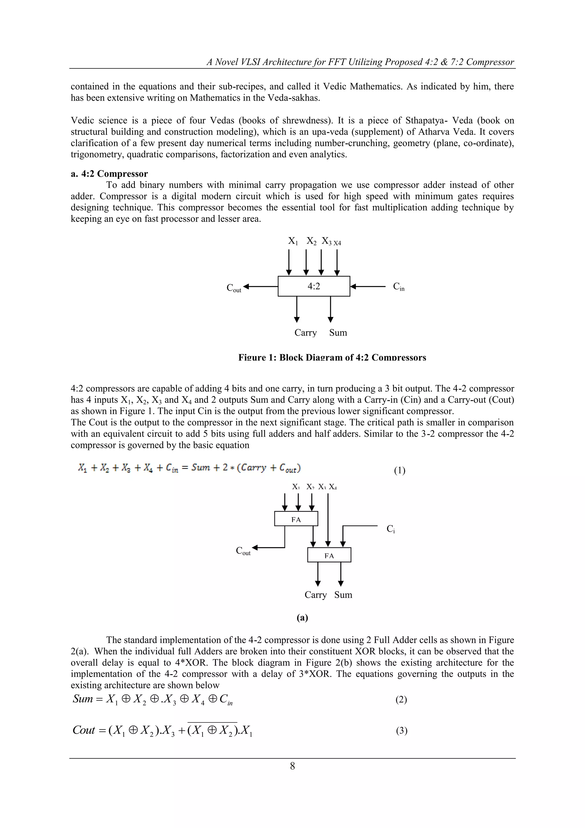
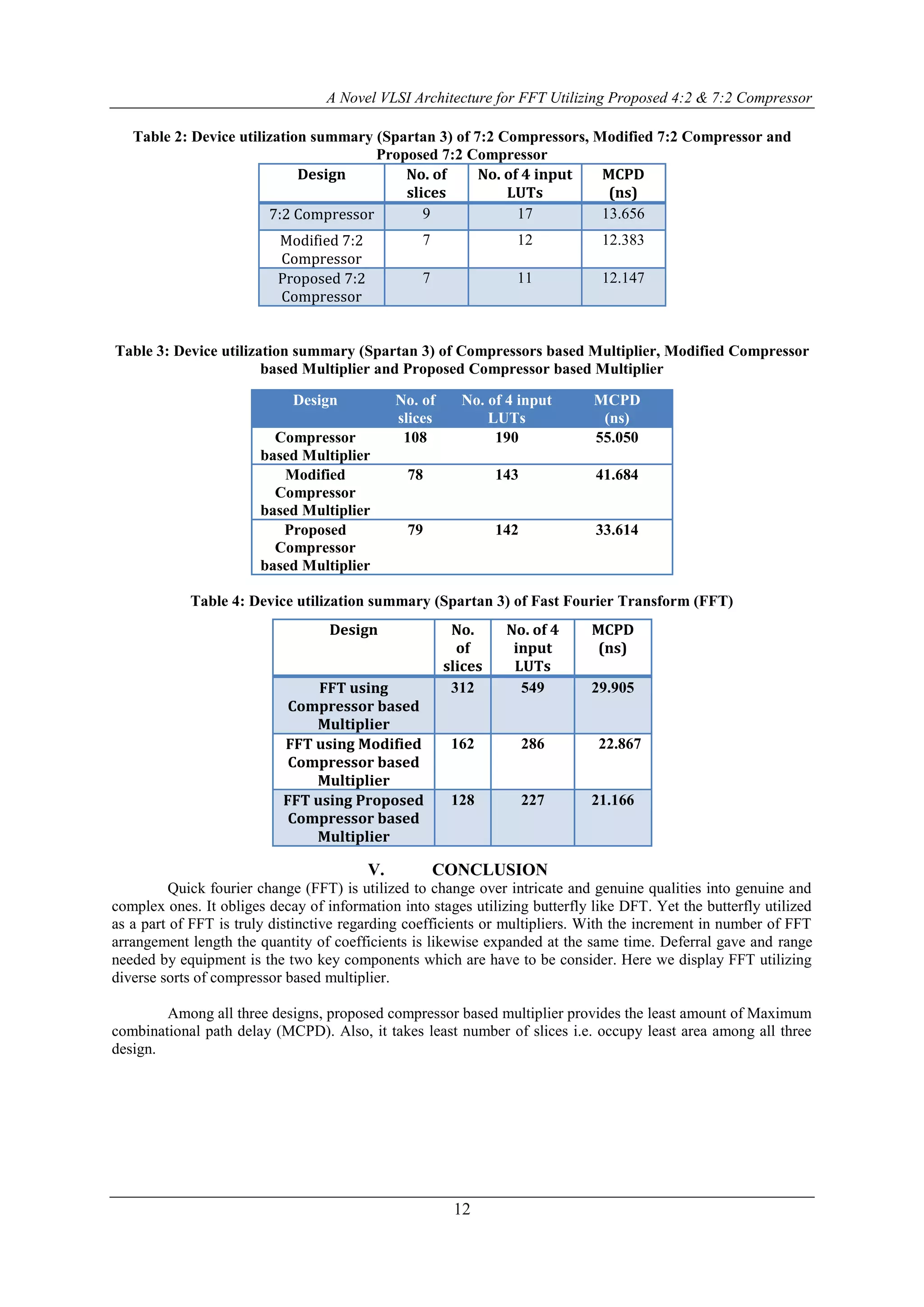
A Novel VLSI Architecture for FFT Utilizing Proposed 4:2 & 7:2
Compressor
Mamta Raj, Prof. Sanket Choudhary, Dr. Soni Changlani
M.Tech Scholar, Electronics and Communication Department, LNCTS Bhopal, India
Assistant Professor, Electronics and Communication Department, LNCTS Bhopal, India
HOD, Electronics and Communication Department,LNCTS Bhopal, India
Abstract:- With the appearance of new innovation in the fields of VLSI and correspondence, there is likewise a
perpetually developing interest for fast transforming and low range outline. It is likewise a remarkable certainty
that the multiplier unit structures a fundamental piece of processor configuration. Because of this respect, rapid
multiplier architectures turn into the need of the day. In this paper, we acquaint a novel structural engineering
with perform high velocity duplication utilizing old Vedic math's strategies. Another fast approach using 4:2
compressors and novel 7:2 compressors for expansion has additionally been joined in the same and has been
investigated. Upon examination, the compressor based multiplier present in this paper, is just about two times
quicker than the mainstream routines for augmentation. Likewise we outline a FFT utilizing compressor based
multiplier. This all configuration and examinations were done on a Xilinx Spartan 3e arrangement of FPGA and
the timing and zone of the outline, on the same have been ascertained.
Keywords:- Fast Fourier Transform (FFT), 4:2 Compressor, Modified 4:2 Compressor, 7:2 Compressor.
I. INTRODUCTION
Advanced sign transforming (DSP) is the scientific control of a data sign to change or enhance it
somehow. It is described by the representation of discrete time, discrete recurrence, or other discrete area
motions by a succession of numbers or images and the transforming of these signs [1].
The objective of DSP is for the most part to gauge, channel and/or pack nonstop certifiable simple
signs. The principal step is ordinarily to change over the sign from a simple to an advanced structure, by
inspecting and after that digitizing it utilizing a simple to-computerized converter (ADC), which transforms the
simple sign into a surge of numbers. Be that as it may, regularly, the obliged yield sign is an alternate simple
yield signal, which obliges a computerized to-simple converter (DAC). Regardless of the possibility that this
methodology is more unpredictable than simple handling and has a discrete worth range, the utilization of
computational energy to advanced sign preparing takes into account numerous points of interest over simple
transforming in numerous applications, for example, slip recognition and amendment in transmission and also
information pressure. DSP calculations have long been run on standard PCs, and in addition on specific
processors called advanced sign processor and deliberately manufactured equipment, for example, application-
particular incorporated circuit (ASICs). Today there are extra advancements utilized for computerized sign
handling including all the more capable broadly useful chip, field-programmable door clusters (FPGAs),
advanced sign controllers (basically for modern applications, for example, engine control), and stream
processors, among others [2-3]. The FFT is a standout amongst the most generally utilized computerized sign
handling calculation. As of late, FFT processor has been broadly utilized as a part of computerized sign handling
field sought OFDM, MIMO-OFDM correspondence frameworks. FFT/IFFT processors are key parts for an
orthogonal recurrence division multiplexing (OFDM) based remote IEEE 802.16 broadband correspondence
framework; it is a standout amongst the most complex and escalated processing module of different remote
guidelines physical layer (ofdm-802.11a, MIMO-OFDM 802.11, 802.16,802.16e) [4].
II. COMPRESSOR BASED MULTIPLIER
Vedic science is an antiquated quick figuring math system which is taken from recorded old book of
intelligence. Vedic science is an antiquated Vedic math which gives the exceptional procedure of mental
estimation with the assistance of straightforward tenets and standards. Swami Bharati Krishna Tirtha (1884-
1960), previous Jagadguru Sankaracharya of Puri selected arrangement of 16 Sutras (axioms) and 13 Sub -
Sutras (culminations) from the Atharva Veda. He created strategies and methods for opening up the standards](https://image.slidesharecdn.com/b1140713-150529052137-lva1-app6891/75/A-Novel-VLSI-Architecture-for-FFT-Utilizing-Proposed-4-2-7-2-Compressor-1-2048.jpg)
![A Novel VLSI Architecture for FFT Utilizing Proposed 4:2 & 7:2 Compressor
13
REFERENCES
[1]. Sushma R. Huddar and Sudhir Rao, Kalpana M., “Novel High Speed Vedic Mathematics Multiplier
using Compressors ”, 978-1-4673-5090-7/13/$31.00 ©2013 IEEE.
[2]. S. S. Kerur, Prakash Narchi, Jayashree C N, Harish M Kittur and Girish V A, “Implementation of
Vedic multiplier for Digital Signal Processing”, International Conference on VLSI, Communication &
Instrumentation (ICVCI) 2011, Proceedings published by International Joural of Computer
Applications® (IJCA), pp.1-6.
[3]. Himanshu Thapaliyal and M.B Srinivas, “VLSI Implementation of RSA Encryption System Using
Ancient Indian Vedic Mathematics”, Center for VLSI and Embedded System Technologies,
International Institute of Information Technology Hyderabad, India.
[4]. Jagadguru Swami Sri Bharati Krishna Tirthaji Maharaja, “Vedic Mathematics: Sixteen simple
Mathematical Formulae from the Veda”, Delhi(2011).
[5]. Sumit Vaidya and Depak Dandekar. “Delay-power perfor-mance comparison of multipliers in VLSI
circuit design”. International Journal of Computer Networks & Communications (IJCNC), Vol.2, No.4,
July 2010.
[6]. P. D. Chidgupkar and M. T. Karad, “The Implementation of Vedic Algorithms in Digital Signal
Procesing”, Global J. of Eng. Edu, Vol.8, No.2, 204, UICEE Published in Australia.
[7]. Asmita Haveliya, “Design and Simulation of 32-Point FFT Using Radix-2 Algorithm for FPGA
Implementation”, Second International Conference on Advanced Computing & Communication
Technologies IEEE 2012.
[8]. S. Correa, L. C. Freitas, A. Klautau and J. C. W. A. Costa, “VHDL Implementation of a Flexible and
Synthesizable FFT Processor”, IEEE LATIN AMERICA TRANSACTIONS, VOL. 10, NO. 1, JAN.
2012.
[9]. Kamaru Adzha Bin Kadiran. “Design and Implementation of OFDM Transmitter and Receiver on
FPGA Hardware”, November 2005.](https://image.slidesharecdn.com/b1140713-150529052137-lva1-app6891/75/A-Novel-VLSI-Architecture-for-FFT-Utilizing-Proposed-4-2-7-2-Compressor-7-2048.jpg)

The document presents a novel VLSI architecture for fast Fourier transform (FFT) using 4:2 and 7:2 compressors aimed at enhancing speed and efficiency in digital signal processing. It demonstrates that the proposed compressor-based multiplier achieves nearly double the speed compared to conventional methods and outlines the design and simulation results using Xilinx FPGA. The findings show significant improvements in delay and area utilization for FFT implementations using the outlined architectural innovations.


![Coded Agents – with UiPath SDK + LangGraph [Virtual Hands-on Workshop]](https://cdn.slidesharecdn.com/ss_thumbnails/codedagentsdeck-251215155422-5497c599-thumbnail.jpg?width=640&height=640&fit=bounds)


