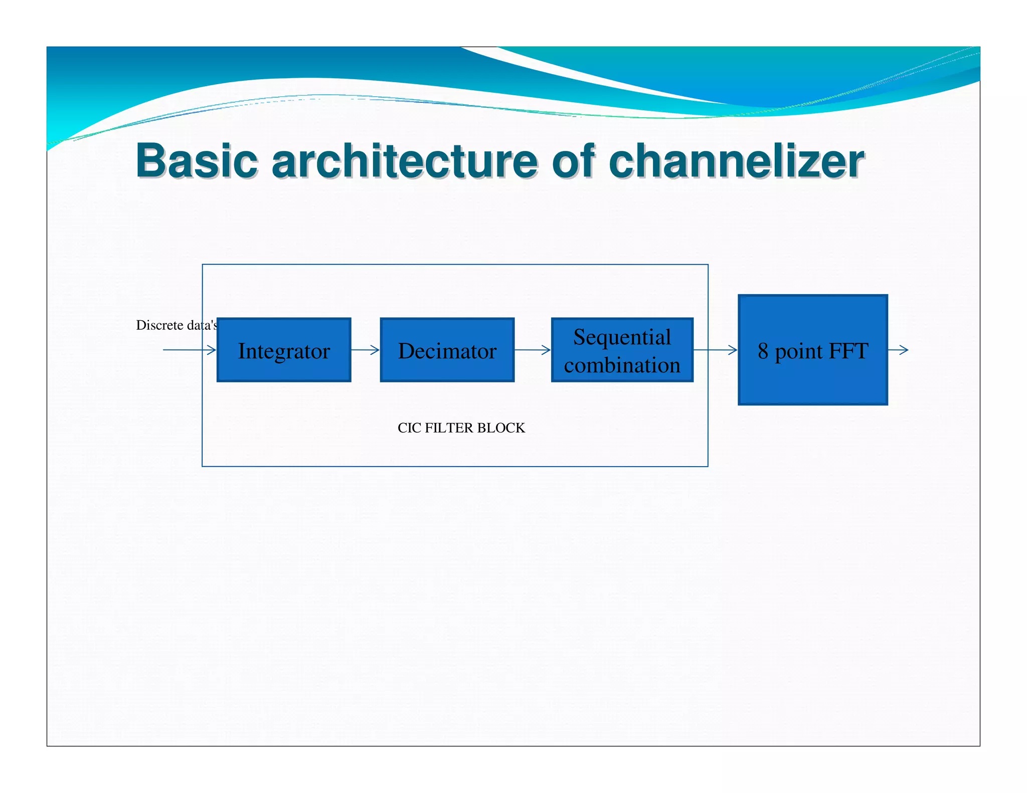
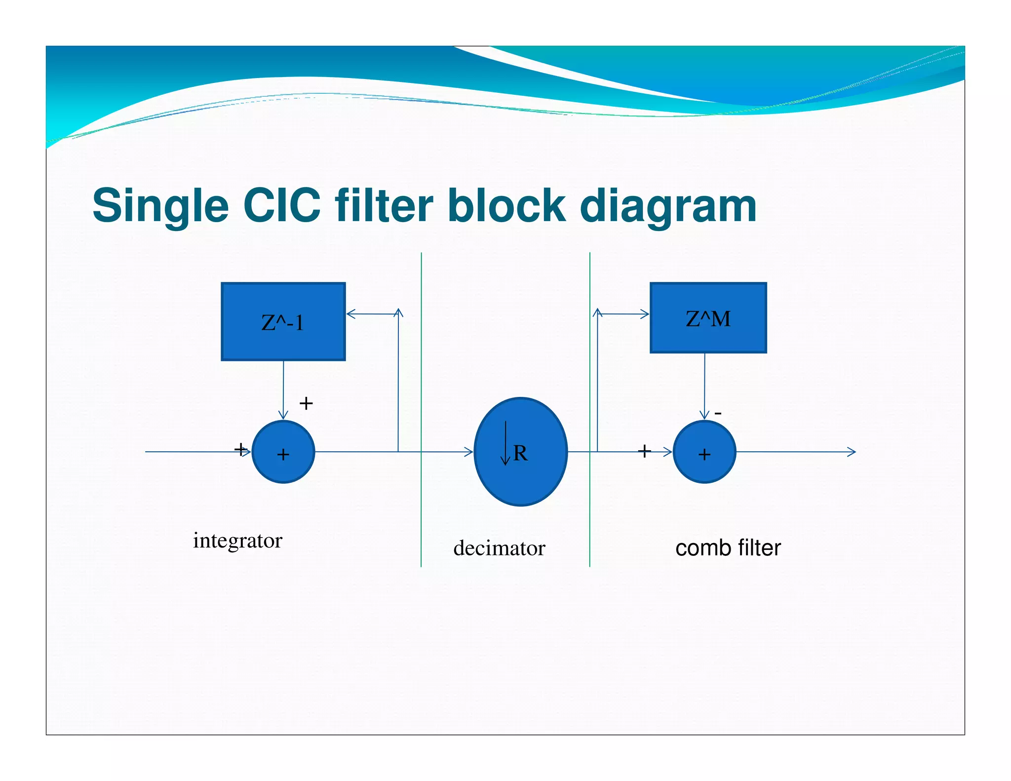
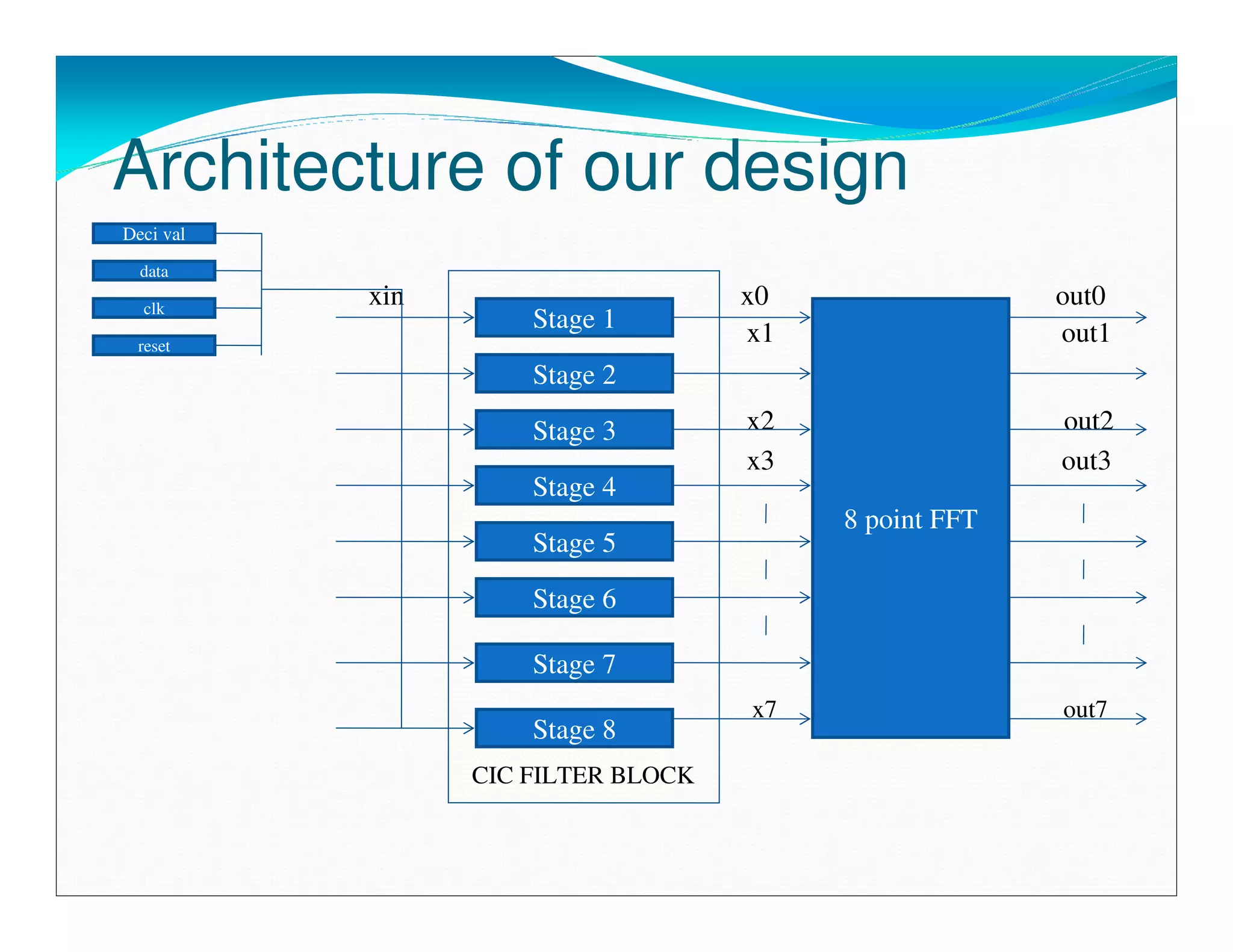
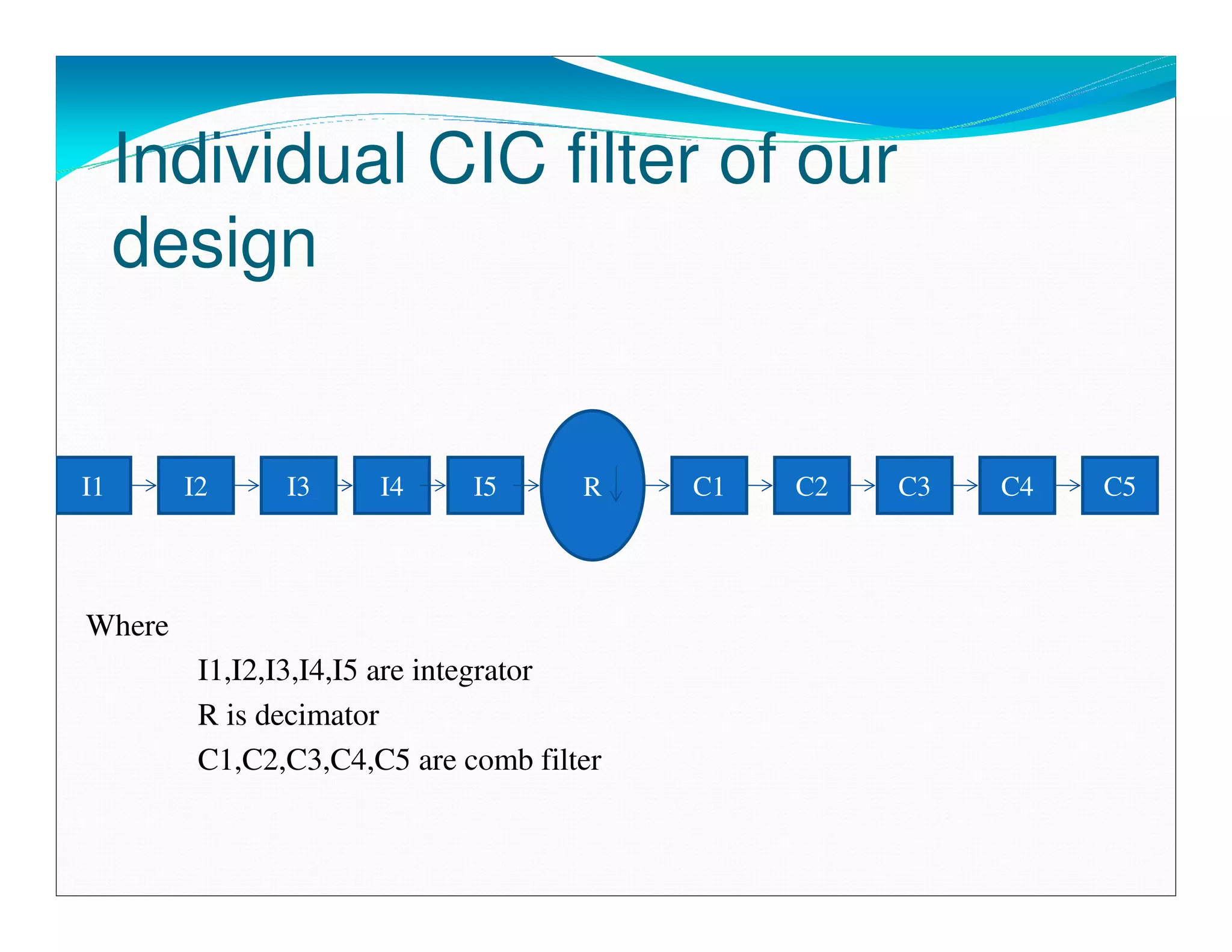
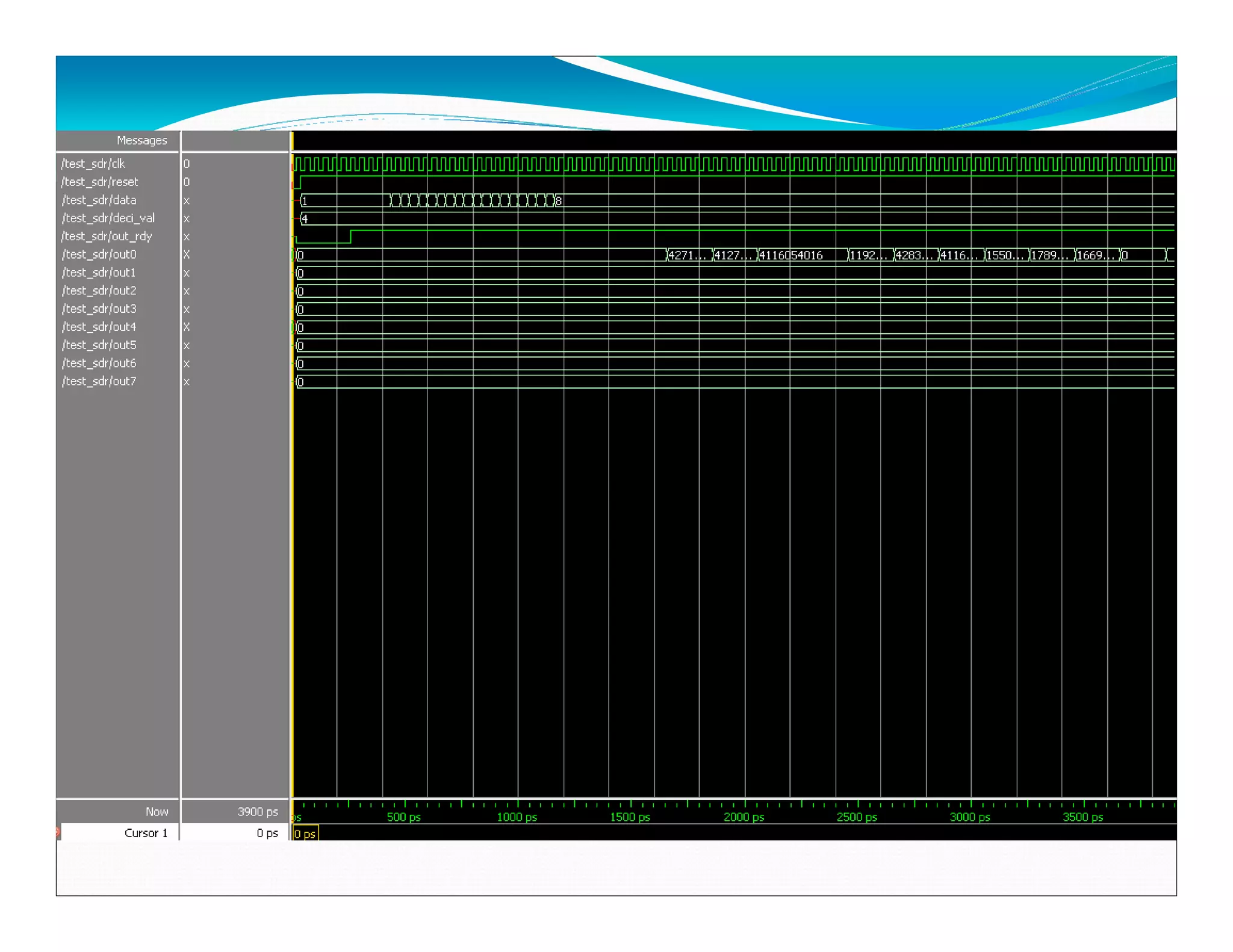
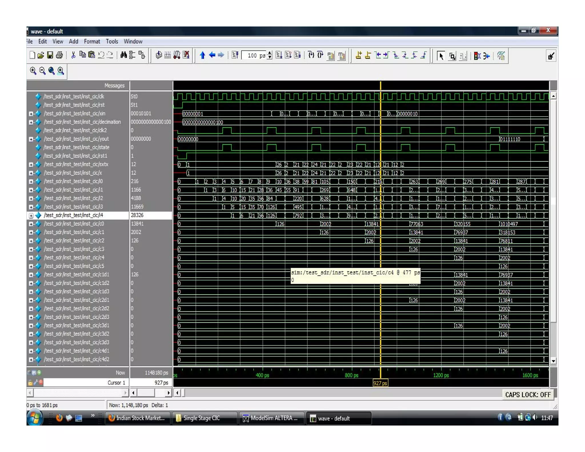
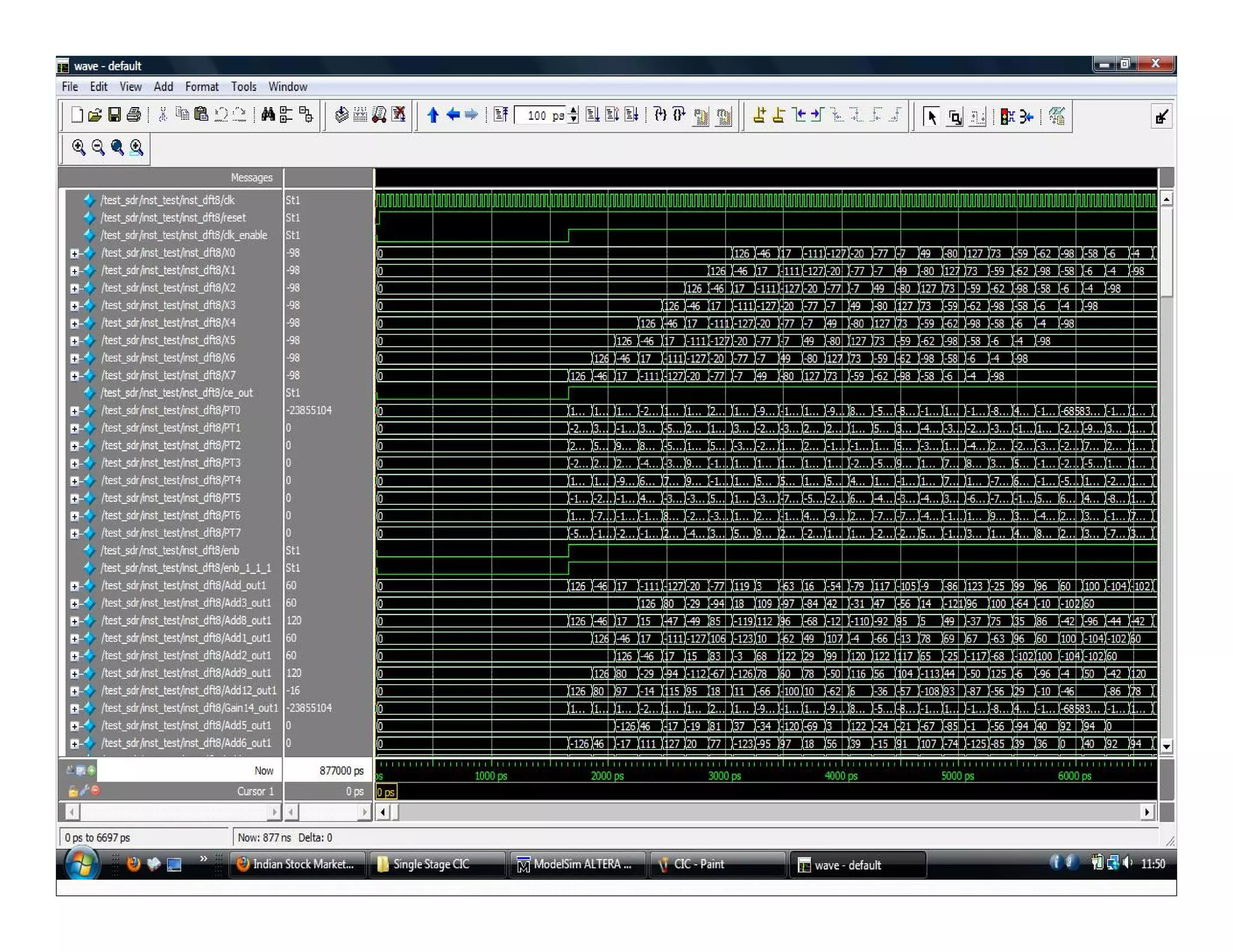
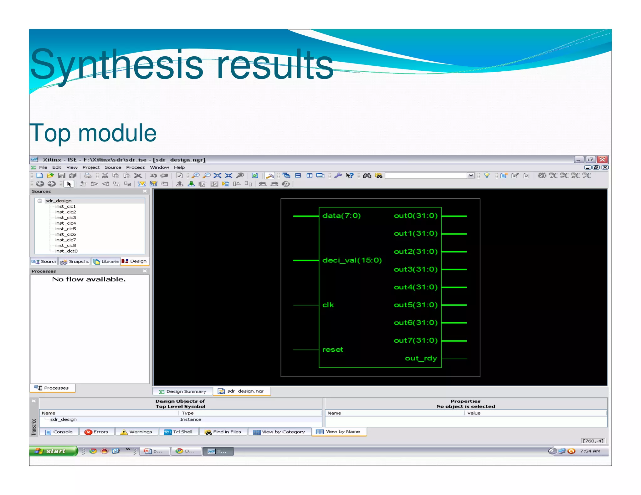
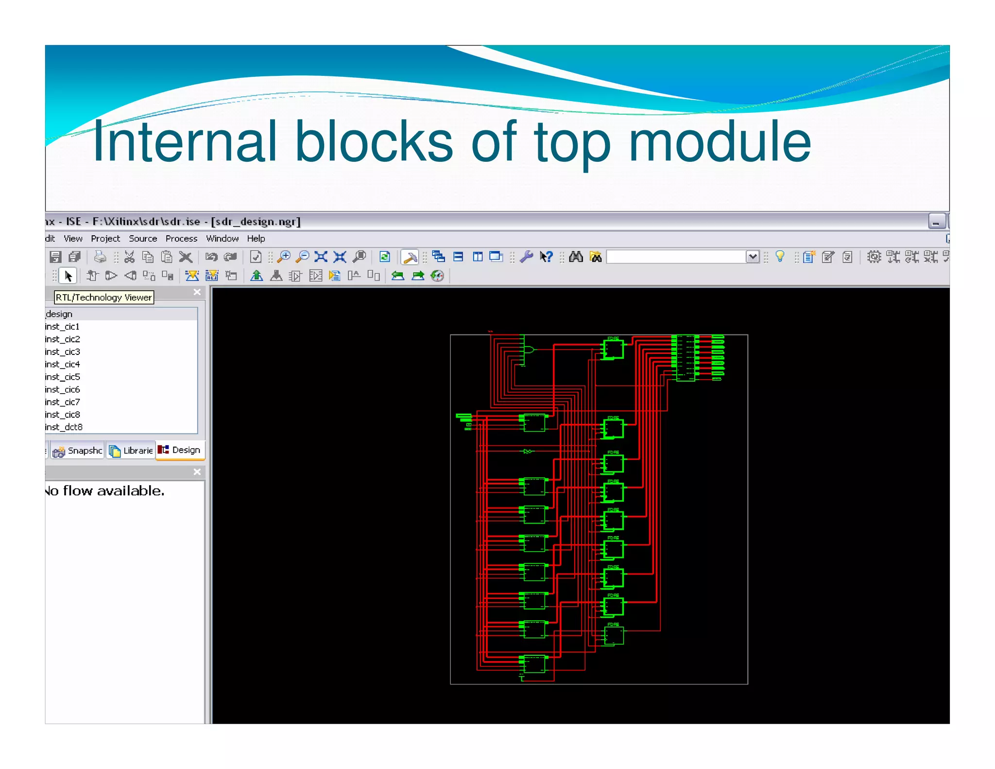
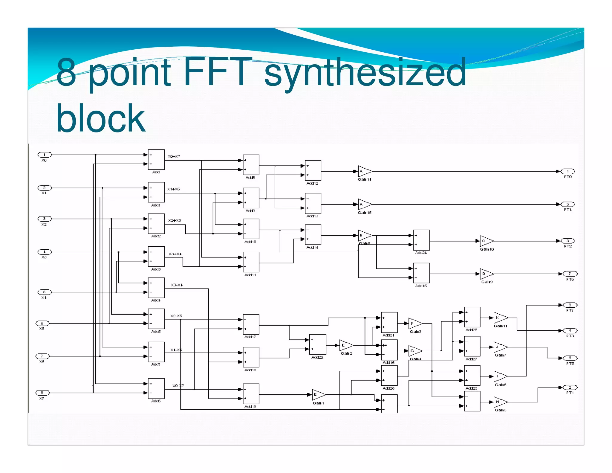
POWER EFFICIENT
CHANNELIZER FOR SOFTWARE
 DEFINED RADIO USING VLSI
Overview
 Objective                        Proposed design of our
 Basic architecture of            channelizer
 channelizer                      Architecture of our design
 CIC filter                       Simulation results
 Fast Fourier transform           Synthesis results
 What is software defined radio   Conclusion
 Field programmable gate array    Reference
objective
 The objective of our project is to design a power efficient
 channelizer for software defined radio.
 We have proposed a model of increased stage CIC filter
 and FFT for channelizer.
 For designing model sim altera is used for simulation
 purpose and xilinz ISE is used for synthesis.
Basic architecture of channelizer


Discrete data's
                                                   Sequential
                  Integrator   Decimator                        8 point FFT
                                                  combination

                               CIC FILTER BLOCK
Cascaded Integrator-Comb
(CIC) Filter
 Used to achieve arbitrary and large sample rate changes in
 digital systems.
 Used as decimation or interpolation filters.
 Efficiently implemented without multipliers, utilizing only
 adders and subtractors.
Single CIC filter block diagram

            Z^-1                      Z^M


                 +                         -
        +    +            R      +     +


    integrator       decimator       comb filter
Features
 1-32-bit input data width.
 1-8 cascaded stages.
 1-4 cycles differential delay.
 Run-time programmable for both decimation and
 interpolation.
Cont…
2-16,384 decimation and interpolation sampling rate
factor.
Multi-channel (up to 4 channels) support for both
decimation and interpolation.
Fully synchronous, single-clock design.
Integrator
 An integrator is a single-pole IIR filter .
 with a unity feedback coefficient.
 operating at a higher sampling rate, fS.
Comb filter
 A comb is a FIR filter .
 with M unity differential delays .
 operating at a lower sampling rate.
Fast Fourier transform
 An efficient algorithm to compute the discrete Fourier
 transform (DFT) and its inverse.
 An FFT computes the DFT and produces exactly the
 same result as evaluating the DFT.
 Difference is that an FFT is much faster.
 DFT of N points takes O(N 2) arithmetical operations,
 FFT take only O(N log N) operations.
What is Software Defined
Radio?
 A collection of hardware and software technologies.
 Radio in which some or all of the physical layer functions
 are software defined.
 Radio’s operating functions are implemented through
 modifiable software or firmware .
 Operating on programmable processing technologies.
Benefits of SDR

 For Radio Equipment Manufacturers and System
 Integrators.
 For Radio Service Providers.
 For End Users - from business travelers to soldiers on the
 battlefield.
Field programmable gate array

An integrated circuit designed to be configured by the
customer or designer after manufacturing.
Configuration is generally specified using a hardware
description language (HDL).
Contain programmable logic components called "logic
blocks“.
Hierarchy of reconfigurable interconnects that allow the
blocks to be "wired together“.
FPGA design and programming

 The HDL form is suited to work with large structures .
 It's possible to just specify numerically rather than having
 to draw every piece by hand.
 Electronic design automation tool is used and technology-
 mapped netlist is generated.
 The netlist can then be fitted to the actual FPGA
 architecture using a process called place-and-route.
Conti…
 The user will validate the map, place and route results
 Once the design and validation process is complete
 The binary file generated is used to reconfigure the FPGA.
Proposed design of
channelizer
 5 stage integrator and 5 stage comb filter with one
 decimator .
 To increase efficiency totally there are 8 complete stages
 of CIC.
 An 8 point FFT block.
Architecture of our design
Deci val
  data

  clk
           xin                      x0                 out0
                     Stage 1
 reset
                                    x1                 out1
                     Stage 2
                     Stage 3        x2        x1       out2
                                    x3                 out3
                     Stage 4
                                         8 point FFT
                     Stage 5

                     Stage 6

                     Stage 7
                                    x7                 out7
                     Stage 8
                 CIC FILTER BLOCK
Individual CIC filter of our
     design


I1      I2     I3     I4     I5      R    C1   C2   C3   C4   C5


Where
         I1,I2,I3,I4,I5 are integrator
         R is decimator
         C1,C2,C3,C4,C5 are comb filter
Sample coding of integrator
                          else
 For integrator section
                               begin
 always @(posedge clk)
                                x<=xin;
 begin
                                rst1<=1'b1;
 if(~rst)
                                i0<=i0+sxtx;
      begin
                          integrator 1
      i0<=26'd0;
                                 i1<=i1+i0;
      i1<=26'd0;
                          integrator 2
      i2<=26'd0;
                                i2<=i2+i1;
      i3<=26'd0;
                          integrator 3
      i4<=26'd0;
                                 i3<=i3+i2;
      rst1<=1'b0;
                          integrator 4
      end
                                 i4<=i4+i3;
                          integrator 5
                               end
Simulation results
Synthesis results
Top module
Internal blocks of top module
8 point FFT synthesized
block
CONCLUSION
Efficiency in terms of architecture optimizations such as
those made in the Polyphase FFT.
Implementation aspects leading to smaller area, low
power, radiation hardness and low cost seem very
promising.
The designed channelizer can be utilized in real time SDR
channel.
There is promising decrease in noise by the design.
REFERENCES
1. R.E. Chrochier et al., “Multirate Digital Signal Processing”,
Prentice Hall, 1981.
2. Package”, GOMAC 2002 Digest of Papers.
3. A.M. Badda and M. Donati, “The Software Defined Radio
Technique Applied to the RF Front-End for Cellular Mobile
Systems”, in Software Radio Technologies and Services”,
Editor Enrico Del Re, Springer-Verlog 2001.
4. P.P Vaidyanathan, “Multirate Digital Filters, Filter Banks,
Polyphase Networks and Applications: A Tutorial”, Proc.
IEEE, Vol. 78, pp 56-93, 1990
5. K.Roy, et. al., “Hardware Architecture and VLSI
Implementation of a Low-Power High-Performance Polyphase
Channelizer with Applications to Subband Adaptive Filtering”,
IEEE International Conference on Acoustics, Speech, and
Signal Processing 2004.
6. K. Roy, et al., “CSDC: a new complexity reduction
technique for parallel multiplierless implementation of digital
FIR filters”, submitted to IEEE Trans. Circuits and Systems II:
Analog and Digital Signal Processing.
7. K. Roy, et al., Low-Power CMOS VLSI Circuit Design,
John Wiley & Sons, Inc., ISBN 0-471-11488-X, 2000.
8. P. McGuirk, J.C. Lyke, et al., “Malleable Signal Processor:
A General-purpose Module for Sensor Integration”, Military
Applications of Programmable Logic Devices (MAPLD) 2000.
9. J. Rooks, J.Lyke, et. al., “Wafer Scale Signal Processors and
Reconfigurable Processors in a 3-
Dimensional C. Poivey, “Radiation Hardness Assurance for
Space Systems,” IEEE NSREC2002 short course,Section V,
2002.
10. C. Poivey, et. al., “Radiation Characterization of
Commercially Available 1M/4Mbit for Space Applications,”
IEEE NSREC 1998 data workshop proceedings, 1998.
PRESENTATION BY
    SOORAJ

SDR channelizer by sooraj

  • 1.
    POWER EFFICIENT CHANNELIZER FORSOFTWARE DEFINED RADIO USING VLSI
  • 2.
    Overview Objective Proposed design of our Basic architecture of channelizer channelizer Architecture of our design CIC filter Simulation results Fast Fourier transform Synthesis results What is software defined radio Conclusion Field programmable gate array Reference
  • 3.
    objective The objectiveof our project is to design a power efficient channelizer for software defined radio. We have proposed a model of increased stage CIC filter and FFT for channelizer. For designing model sim altera is used for simulation purpose and xilinz ISE is used for synthesis.
  • 4.
    Basic architecture ofchannelizer Discrete data's Sequential Integrator Decimator 8 point FFT combination CIC FILTER BLOCK
  • 5.
    Cascaded Integrator-Comb (CIC) Filter Used to achieve arbitrary and large sample rate changes in digital systems. Used as decimation or interpolation filters. Efficiently implemented without multipliers, utilizing only adders and subtractors.
  • 6.
    Single CIC filterblock diagram Z^-1 Z^M + - + + R + + integrator decimator comb filter
  • 7.
    Features 1-32-bit inputdata width. 1-8 cascaded stages. 1-4 cycles differential delay. Run-time programmable for both decimation and interpolation.
  • 8.
    Cont… 2-16,384 decimation andinterpolation sampling rate factor. Multi-channel (up to 4 channels) support for both decimation and interpolation. Fully synchronous, single-clock design.
  • 9.
    Integrator An integratoris a single-pole IIR filter . with a unity feedback coefficient. operating at a higher sampling rate, fS.
  • 10.
    Comb filter Acomb is a FIR filter . with M unity differential delays . operating at a lower sampling rate.
  • 11.
    Fast Fourier transform An efficient algorithm to compute the discrete Fourier transform (DFT) and its inverse. An FFT computes the DFT and produces exactly the same result as evaluating the DFT. Difference is that an FFT is much faster. DFT of N points takes O(N 2) arithmetical operations, FFT take only O(N log N) operations.
  • 12.
    What is SoftwareDefined Radio? A collection of hardware and software technologies. Radio in which some or all of the physical layer functions are software defined. Radio’s operating functions are implemented through modifiable software or firmware . Operating on programmable processing technologies.
  • 13.
    Benefits of SDR For Radio Equipment Manufacturers and System Integrators. For Radio Service Providers. For End Users - from business travelers to soldiers on the battlefield.
  • 14.
    Field programmable gatearray An integrated circuit designed to be configured by the customer or designer after manufacturing. Configuration is generally specified using a hardware description language (HDL). Contain programmable logic components called "logic blocks“. Hierarchy of reconfigurable interconnects that allow the blocks to be "wired together“.
  • 15.
    FPGA design andprogramming The HDL form is suited to work with large structures . It's possible to just specify numerically rather than having to draw every piece by hand. Electronic design automation tool is used and technology- mapped netlist is generated. The netlist can then be fitted to the actual FPGA architecture using a process called place-and-route.
  • 16.
    Conti… The userwill validate the map, place and route results Once the design and validation process is complete The binary file generated is used to reconfigure the FPGA.
  • 17.
    Proposed design of channelizer 5 stage integrator and 5 stage comb filter with one decimator . To increase efficiency totally there are 8 complete stages of CIC. An 8 point FFT block.
  • 18.
    Architecture of ourdesign Deci val data clk xin x0 out0 Stage 1 reset x1 out1 Stage 2 Stage 3 x2 x1 out2 x3 out3 Stage 4 8 point FFT Stage 5 Stage 6 Stage 7 x7 out7 Stage 8 CIC FILTER BLOCK
  • 19.
    Individual CIC filterof our design I1 I2 I3 I4 I5 R C1 C2 C3 C4 C5 Where I1,I2,I3,I4,I5 are integrator R is decimator C1,C2,C3,C4,C5 are comb filter
  • 20.
    Sample coding ofintegrator else For integrator section begin always @(posedge clk) x<=xin; begin rst1<=1'b1; if(~rst) i0<=i0+sxtx; begin integrator 1 i0<=26'd0; i1<=i1+i0; i1<=26'd0; integrator 2 i2<=26'd0; i2<=i2+i1; i3<=26'd0; integrator 3 i4<=26'd0; i3<=i3+i2; rst1<=1'b0; integrator 4 end i4<=i4+i3; integrator 5 end
  • 22.
  • 24.
  • 25.
  • 26.
    8 point FFTsynthesized block
  • 27.
    CONCLUSION Efficiency in termsof architecture optimizations such as those made in the Polyphase FFT. Implementation aspects leading to smaller area, low power, radiation hardness and low cost seem very promising. The designed channelizer can be utilized in real time SDR channel. There is promising decrease in noise by the design.
  • 28.
    REFERENCES 1. R.E. Chrochieret al., “Multirate Digital Signal Processing”, Prentice Hall, 1981. 2. Package”, GOMAC 2002 Digest of Papers. 3. A.M. Badda and M. Donati, “The Software Defined Radio Technique Applied to the RF Front-End for Cellular Mobile Systems”, in Software Radio Technologies and Services”, Editor Enrico Del Re, Springer-Verlog 2001. 4. P.P Vaidyanathan, “Multirate Digital Filters, Filter Banks, Polyphase Networks and Applications: A Tutorial”, Proc. IEEE, Vol. 78, pp 56-93, 1990 5. K.Roy, et. al., “Hardware Architecture and VLSI Implementation of a Low-Power High-Performance Polyphase Channelizer with Applications to Subband Adaptive Filtering”, IEEE International Conference on Acoustics, Speech, and Signal Processing 2004.
  • 29.
    6. K. Roy,et al., “CSDC: a new complexity reduction technique for parallel multiplierless implementation of digital FIR filters”, submitted to IEEE Trans. Circuits and Systems II: Analog and Digital Signal Processing. 7. K. Roy, et al., Low-Power CMOS VLSI Circuit Design, John Wiley & Sons, Inc., ISBN 0-471-11488-X, 2000. 8. P. McGuirk, J.C. Lyke, et al., “Malleable Signal Processor: A General-purpose Module for Sensor Integration”, Military Applications of Programmable Logic Devices (MAPLD) 2000. 9. J. Rooks, J.Lyke, et. al., “Wafer Scale Signal Processors and Reconfigurable Processors in a 3- Dimensional C. Poivey, “Radiation Hardness Assurance for Space Systems,” IEEE NSREC2002 short course,Section V, 2002. 10. C. Poivey, et. al., “Radiation Characterization of Commercially Available 1M/4Mbit for Space Applications,” IEEE NSREC 1998 data workshop proceedings, 1998.
  • 30.