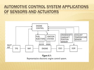
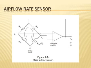
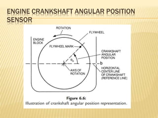
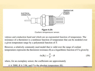
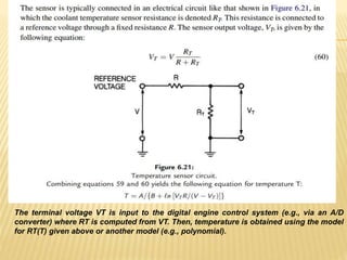
Module 2
Sensors and Actuators
SYLLABUS
 Sensors and Actuators: Introduction to sensors and transducers-Types-Air
flow rate sensor, Engine crankshaft angular position senor, Engine speed sensor,
Timing sensor, Throttle angle sensor, Pressure sensor, Temperature sensors,
Pressure sensor-Flow sensor, Exhaust gas oxygen sensors, Knock Sensor,
Engine torque sensors, Automotive engine control actuators, Exhaust gas
recirculation actuator.
INTRODUCTION
 In any control system, sensors provide measurements of important plant
variables in a format suitable for the digital microcontroller.
 Similarly, actuators are electrically operated devices that regulate inputs to the
plant that directly controls its output.
 For example, as we shall see, fuel injectors are electrically driven actuators that
regulate the flow of fuel into an engine for engine control applications.
AUTOMOTIVE CONTROL SYSTEM APPLICATIONS
OF SENSORS AND ACTUATORS
VARIABLES TO BE MEASURED
THE SUPERSET OF VARIABLES SENSED IN ENGINE CONTROL
INCLUDES THE FOLLOWING
1. mass airflow (MAF) rate
2. exhaust gas oxygen concentration
3. throttle plate angular position
4. crankshaft angular position/RPM
5. camshaft angular position
6. coolant temperature
7. intake air temperature
8. ambient air pressure
9. ambient air temperature
10. manifold absolute pressure (MAP)
11. differential exhaust gas pressure (relative
to ambient)
12. vehicle speed
13. transmission gear selector position
14. actual transmission gear, and
15. various pressures.
These switches include the following:
1. air conditioner clutch engaged
2. brake on/off
3. wide open throttle
4. closed throttle, and
5. transmission gear selection.
AIRFLOW RATE SENSOR
• The concept of such an airflow sensor is based upon the variation in resistance of
the two terminal sensing element with temperature.
•A current is passed through the sensing element supplying power to it, thereby
raising its temperature and changing its resistance.
•When this heated sensing element is placed in a moving air stream (or other
flowing gas), heat is removed from the sensing element as a function of the mass
flow rate of the air passing the element as well as the temperature difference
between the moving air and the sensing element.
•For a constant supply current (i.e., heating rate), the temperature at the element
changes in proportion to the heat removed by the moving air stream, thereby
producing a change in its resistance.
•A convenient model for the sensing element resistance (RSE) at temperature (T) is
given by
The mass flow rate of the moving air stream is measured via a measurement of the
change in resistance.
 In the bridge circuit, three resistors (R1, R2, and R3) are connected as depicted in Figure
6.2 along with a resistive sensing element denoted RSE(T).
 This sensing element consists of a thin film of conducting (e.g., Ni) or semiconducting
material that is deposited on an insulating substrate.
 The voltages V1 and V2 (depicted in Figure 6.2) are connected to the inputs of a
relatively high-gain differential amplifier.
 The output voltage of this amplifier vo is connected to the bridge (as shown in Figure
6.2) and provides the electrical excitation for the bridge.
 This voltage is given by
where G is the amplifier voltage gain
 In this bridge circuit, only that sensing element is placed in the moving air stream whose
mass flow rate is to be measured.
 The other three resistances are mounted such that they are at the same ambient
temperature (Ta) as regards the moving air.
 The combination bridge circuit and differential amplifier form a closed-loop in which
the temperature difference ∆T between the sensing element and the ambient air
temperature remains fixed independent of Ta (which for an automobile can vary by more
than 100 C).
 We discuss the circuit operation first and then explain the compensation for variation in
Ta.
ENGINE CRANKSHAFT ANGULAR POSITION
SENSOR
 The measurement of crankshaft angular position or RPM in
engine control involves principles applicable to rotating shafts.
 In this context, envisioning the engine from the rear is helpful.
 A significant component is the flywheel, a circular steel disk
connected to and rotating with the crankshaft. The flywheel
mark, a designated point on the flywheel, is crucial.
 A reference line is defined as the line through the crankshaft
axis and a point on the engine block (b). In this discussion, the
reference line is considered horizontal.
 Crankshaft angular position is the angle between the reference
line and the line through the axis and the flywheel mark,
illustrating the fundamental principles of measuring rotating
shafts in engine control.
 Imagine that the flywheel is rotated so that the mark is directly on
the reference line.
 This is an angular position of zero degrees. For our purposes,
assume that this angular position corresponds to the No. 1
cylinder at TDC (top dead center) on either intake or power
strokes.
 As the crankshaft rotates, this angle increases from zero to 360 in
one revolution.
 However, one full engine cycle from intake through exhaust
requires two complete revolutions of the crankshaft; that is, one
complete engine cycle corresponds to the crankshaft angular
position going from zero to 720.
 During each cycle, it is important to measure the crankshaft
position relative to the reference for each cycle in each cylinder.
 This information is used by the electronic engine controller to set
ignition timing and, in most cases, to set the fuel injector pulse
timing.
THROTTLE ANGLE SENSOR
 Consider now a resistive material formed in a segment of a circle
of radius r as depicted in Figure 6.19. Let the radial dimension
and the thickness of the material be uniform and small compared
to the circumferential distance along the arc (ra). A movable
metallic contact that pivots about the center of the circular arc
makes contact with the resistive material at an angle a (measured
from a line through the center and the grounded end of the
resistive material). The opposite end of the material (at an angle
amax) is connected to a constant voltage Vs. A structure such as
that depicted in Figure 6.19 is known as a rotary potentiometer
(or just as a potentiometer). Let the total resistance from the end
of the material which is connected to Vs be denoted Rp and the
resistance from the movable contact to ground at any angle a be
denoted R(a). With the assumptions of uniform geometry given
above, this resistance varies linearly with arc length ra. Thus, the
resistance R(a) can be shown to be given by
TEMPERATURE SENSORS
 Temperature (T) is an important parameter throughout the automotive system.
 In the operation of an electronic fuel control system it is vital to know the
temperature of the coolant, the temperature of the inlet air, and the temperature
of the exhaust gas oxygen sensor (a sensor to be discussed in the next section).
 Several sensor configurations are available for measuring these temperatures,
but we can illustrate the basic operation of most of the temperature sensors by
explaining the operation of a typical coolant sensor.
 The temperature sensor for any given application is designed to meet the
expected temperature range.
 For example, a coolant, temperature sensor experiences far lower temperatures
than a sensor exposed to exhaust gases.
TYPICAL COOLANT SENSOR
 A typical coolant sensor, shown in Figure 6.20, consists of a
thermistor mounted in a housing that is designed to be
inserted in the coolant stream. This housing is typically
threaded such that it seals the assembly against coolant
leakage. A thermistor is a two-terminal semiconductor
whose resistance varies inversely with its temperature. The
theory of operation is based upon the influence of
temperature on the charge carrier concentrations which, in
turn, depend upon the difference in energy between the
The terminal voltage VT is input to the digital engine control system (e.g., via an A/D
converter) where RT is computed from VT. Then, temperature is obtained using the model
for RT(T) given above or another model (e.g., polynomial).

Automotive Electronics Sensors and Actuators

  • 1.
  • 2.
    SYLLABUS  Sensors andActuators: Introduction to sensors and transducers-Types-Air flow rate sensor, Engine crankshaft angular position senor, Engine speed sensor, Timing sensor, Throttle angle sensor, Pressure sensor, Temperature sensors, Pressure sensor-Flow sensor, Exhaust gas oxygen sensors, Knock Sensor, Engine torque sensors, Automotive engine control actuators, Exhaust gas recirculation actuator.
  • 3.
    INTRODUCTION  In anycontrol system, sensors provide measurements of important plant variables in a format suitable for the digital microcontroller.  Similarly, actuators are electrically operated devices that regulate inputs to the plant that directly controls its output.  For example, as we shall see, fuel injectors are electrically driven actuators that regulate the flow of fuel into an engine for engine control applications.
  • 4.
    AUTOMOTIVE CONTROL SYSTEMAPPLICATIONS OF SENSORS AND ACTUATORS
  • 5.
    VARIABLES TO BEMEASURED THE SUPERSET OF VARIABLES SENSED IN ENGINE CONTROL INCLUDES THE FOLLOWING 1. mass airflow (MAF) rate 2. exhaust gas oxygen concentration 3. throttle plate angular position 4. crankshaft angular position/RPM 5. camshaft angular position 6. coolant temperature 7. intake air temperature 8. ambient air pressure 9. ambient air temperature 10. manifold absolute pressure (MAP) 11. differential exhaust gas pressure (relative to ambient) 12. vehicle speed 13. transmission gear selector position 14. actual transmission gear, and 15. various pressures.
  • 6.
    These switches includethe following: 1. air conditioner clutch engaged 2. brake on/off 3. wide open throttle 4. closed throttle, and 5. transmission gear selection.
  • 7.
  • 8.
    • The conceptof such an airflow sensor is based upon the variation in resistance of the two terminal sensing element with temperature. •A current is passed through the sensing element supplying power to it, thereby raising its temperature and changing its resistance. •When this heated sensing element is placed in a moving air stream (or other flowing gas), heat is removed from the sensing element as a function of the mass flow rate of the air passing the element as well as the temperature difference between the moving air and the sensing element. •For a constant supply current (i.e., heating rate), the temperature at the element changes in proportion to the heat removed by the moving air stream, thereby producing a change in its resistance. •A convenient model for the sensing element resistance (RSE) at temperature (T) is given by
  • 9.
    The mass flowrate of the moving air stream is measured via a measurement of the change in resistance.
  • 10.
     In thebridge circuit, three resistors (R1, R2, and R3) are connected as depicted in Figure 6.2 along with a resistive sensing element denoted RSE(T).  This sensing element consists of a thin film of conducting (e.g., Ni) or semiconducting material that is deposited on an insulating substrate.  The voltages V1 and V2 (depicted in Figure 6.2) are connected to the inputs of a relatively high-gain differential amplifier.  The output voltage of this amplifier vo is connected to the bridge (as shown in Figure 6.2) and provides the electrical excitation for the bridge.  This voltage is given by where G is the amplifier voltage gain
  • 11.
     In thisbridge circuit, only that sensing element is placed in the moving air stream whose mass flow rate is to be measured.  The other three resistances are mounted such that they are at the same ambient temperature (Ta) as regards the moving air.  The combination bridge circuit and differential amplifier form a closed-loop in which the temperature difference ∆T between the sensing element and the ambient air temperature remains fixed independent of Ta (which for an automobile can vary by more than 100 C).  We discuss the circuit operation first and then explain the compensation for variation in Ta.
  • 14.
  • 15.
     The measurementof crankshaft angular position or RPM in engine control involves principles applicable to rotating shafts.  In this context, envisioning the engine from the rear is helpful.  A significant component is the flywheel, a circular steel disk connected to and rotating with the crankshaft. The flywheel mark, a designated point on the flywheel, is crucial.  A reference line is defined as the line through the crankshaft axis and a point on the engine block (b). In this discussion, the reference line is considered horizontal.  Crankshaft angular position is the angle between the reference line and the line through the axis and the flywheel mark, illustrating the fundamental principles of measuring rotating shafts in engine control.
  • 16.
     Imagine thatthe flywheel is rotated so that the mark is directly on the reference line.  This is an angular position of zero degrees. For our purposes, assume that this angular position corresponds to the No. 1 cylinder at TDC (top dead center) on either intake or power strokes.  As the crankshaft rotates, this angle increases from zero to 360 in one revolution.  However, one full engine cycle from intake through exhaust requires two complete revolutions of the crankshaft; that is, one complete engine cycle corresponds to the crankshaft angular position going from zero to 720.  During each cycle, it is important to measure the crankshaft position relative to the reference for each cycle in each cylinder.  This information is used by the electronic engine controller to set ignition timing and, in most cases, to set the fuel injector pulse timing.
  • 17.
  • 20.
     Consider nowa resistive material formed in a segment of a circle of radius r as depicted in Figure 6.19. Let the radial dimension and the thickness of the material be uniform and small compared to the circumferential distance along the arc (ra). A movable metallic contact that pivots about the center of the circular arc makes contact with the resistive material at an angle a (measured from a line through the center and the grounded end of the resistive material). The opposite end of the material (at an angle amax) is connected to a constant voltage Vs. A structure such as that depicted in Figure 6.19 is known as a rotary potentiometer (or just as a potentiometer). Let the total resistance from the end of the material which is connected to Vs be denoted Rp and the resistance from the movable contact to ground at any angle a be denoted R(a). With the assumptions of uniform geometry given above, this resistance varies linearly with arc length ra. Thus, the resistance R(a) can be shown to be given by
  • 22.
    TEMPERATURE SENSORS  Temperature(T) is an important parameter throughout the automotive system.  In the operation of an electronic fuel control system it is vital to know the temperature of the coolant, the temperature of the inlet air, and the temperature of the exhaust gas oxygen sensor (a sensor to be discussed in the next section).  Several sensor configurations are available for measuring these temperatures, but we can illustrate the basic operation of most of the temperature sensors by explaining the operation of a typical coolant sensor.  The temperature sensor for any given application is designed to meet the expected temperature range.  For example, a coolant, temperature sensor experiences far lower temperatures than a sensor exposed to exhaust gases.
  • 23.
    TYPICAL COOLANT SENSOR A typical coolant sensor, shown in Figure 6.20, consists of a thermistor mounted in a housing that is designed to be inserted in the coolant stream. This housing is typically threaded such that it seals the assembly against coolant leakage. A thermistor is a two-terminal semiconductor whose resistance varies inversely with its temperature. The theory of operation is based upon the influence of temperature on the charge carrier concentrations which, in turn, depend upon the difference in energy between the
  • 25.
    The terminal voltageVT is input to the digital engine control system (e.g., via an A/D converter) where RT is computed from VT. Then, temperature is obtained using the model for RT(T) given above or another model (e.g., polynomial).

Editor's Notes

  • #5 Figure 6.1 depicts a simplified block diagram of an electronic engine control system, showcasing key sensors crucial for engine control. The throttle position sensor (TPS) monitors the throttle plate's position, directly influencing airflow and power output. Fuel injectors, regulated by the electronic engine controller, ensure precise fuel delivery to each cylinder for maintaining a stoichiometric fuel/air mixture. The ignition control system, under electronic engine control, fires spark plugs at optimal times. Additionally, the engine controller governs exhaust gas recirculation (EGR). Various sensors connected to the engine provide critical data, guiding the engine controller's computations, which, in turn, generate output signals to control actuators. This summary outlines the role of sensors in engine control, with a subsequent discussion on the corresponding actuators.
  • #7 In addition to measurements of the above variables, engine control is also based on the status of the vehicle as monitored by a set of switches.
  • #15 In electronic engine control, the angular position of the crankshaft is a crucial parameter measured without direct mechanical contact. This measurement, often referred to as "engine angular position," is essential for engine control functions. The sensor used for this purpose can also calculate the instantaneous angular speed of the crankshaft. Non-contact measurements are preferred, and in automotive electronics, magnetic or optical methods are commonly employed. Magnetic measurements are particularly favored in engine applications due to their resilience against oil, dirt, and other contaminants.
  • #17 In automobiles with electronic engine control systems, angular position qe can be sensed on the crankshaft directly or on the camshaft. Recall that the piston drives the crankshaft directly, while the valves are driven from the camshaft. The camshaft is driven from the crankshaft through a 1:2 reduction drivetrain, which can be gears, belt, or chain. Therefore, the camshaft rotational speed is one-half that of the crankshaft, so the camshaft angular position goes from zero to 360 for one complete engine cycle. Either of these sensing locations can be used in electronic control systems. Although the crankshaft location is potentially superior for accuracy because of torsional and gear backlash errors in the camshaft drivetrain, many production systems locate this sensor such that it measures camshaft position. For measurement of engine position via a crankshaft sensor, an unambiguous measurement of the crankshaft angular position relative to a unique point in the cycle for each cylinder requires some measurement of camshaft position as well as crankshaft position. Typically, it is sufficient to sense camshaft position at one point in a complete revolution. At the present time, there appears to be a trend toward measuring crankshaft position directly rather than indirectly via camshaft position. In principle, it is sufficient for engine control purposes to measure crankshaft/camshaft position at a small number of fixed points. The number of such measurements (or samples), for example, could be determined by the number of cylinders.
  • #18 Still another variable that must be measured for electronic engine control is the throttle plate angular position. In most automobiles, the throttle plate is linked mechanically to the accelerator pedal and moves with it. When the driver depresses the accelerator pedal, this linkage causes the throttle plate angle to increase, allowing more air to enter the engine and thereby increasing engine power. Measurement of the instantaneous throttle angle is important for control purposes, as will be explained in Chapter 7. Most throttle angle sensors are essentially potentiometers. A potentiometer consists of a resistor with a movable contact, as illustrated in Figure 6.18