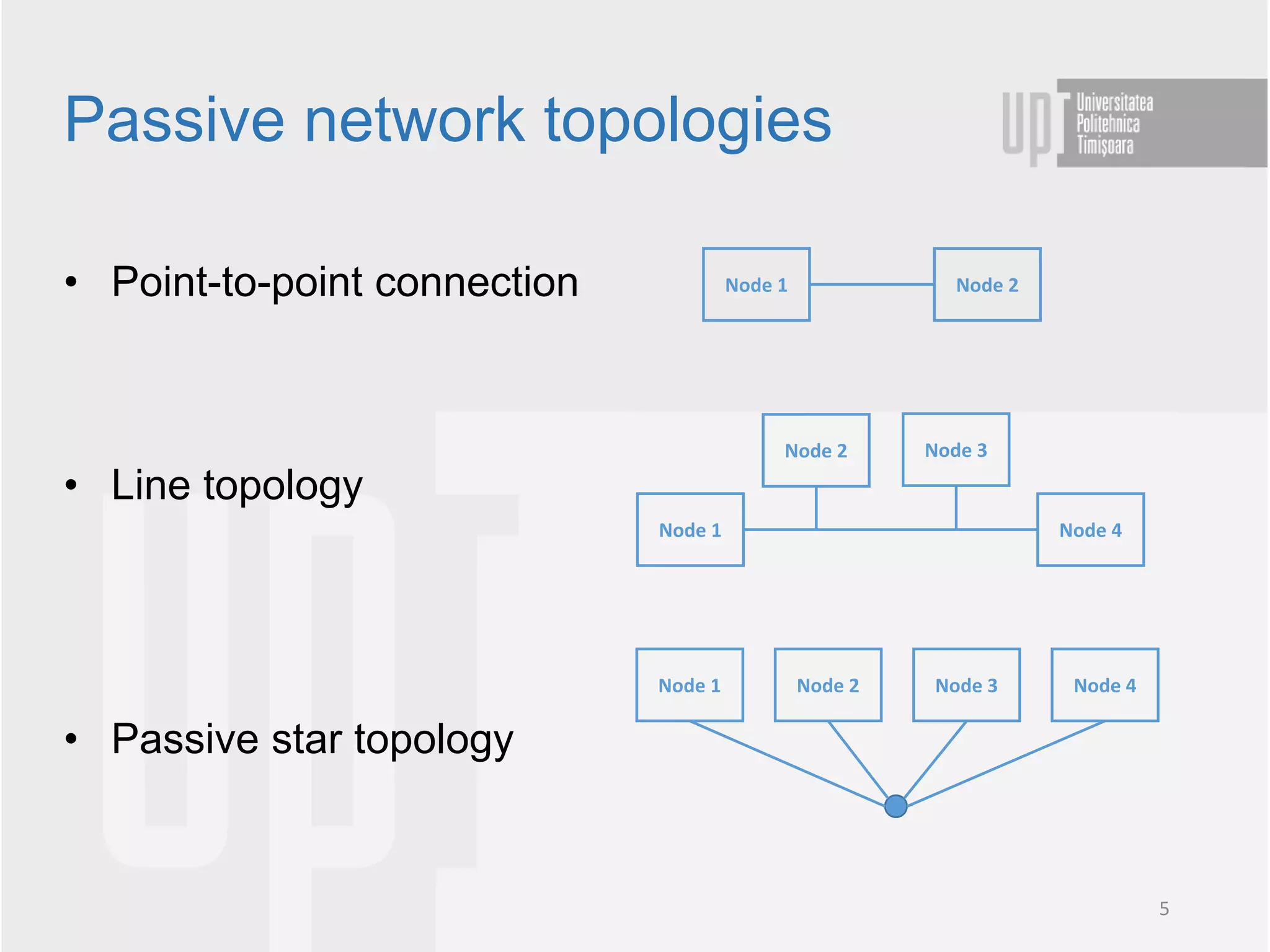
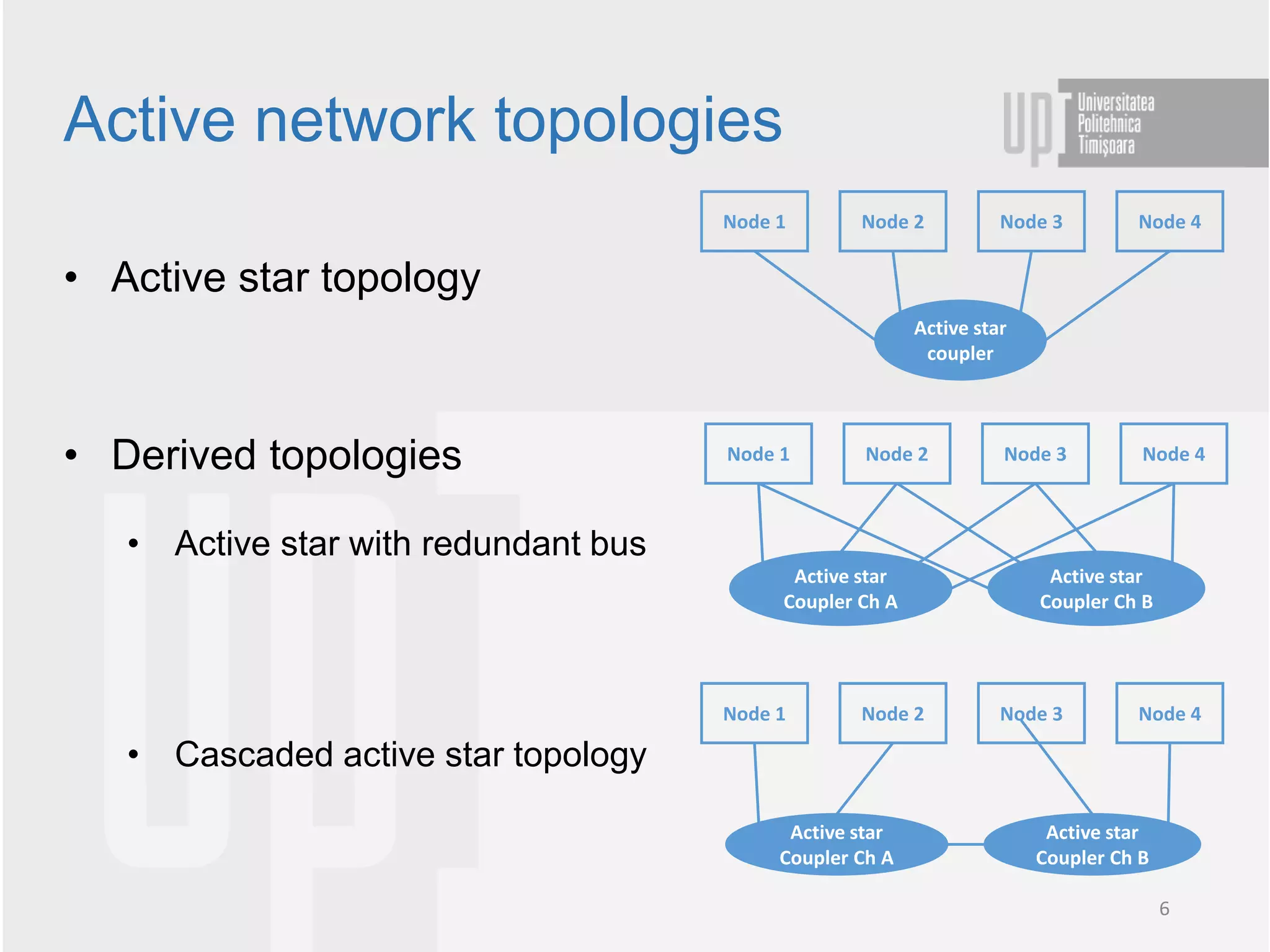
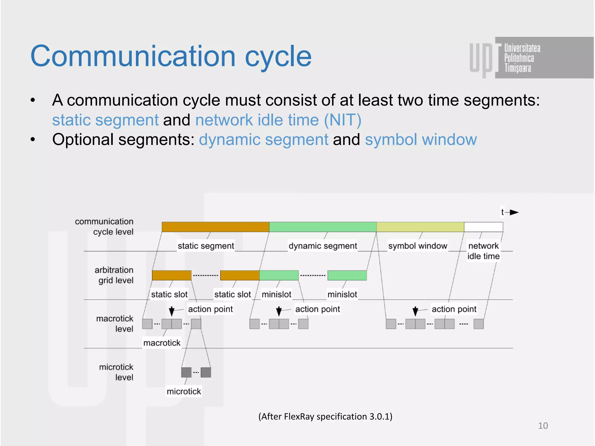
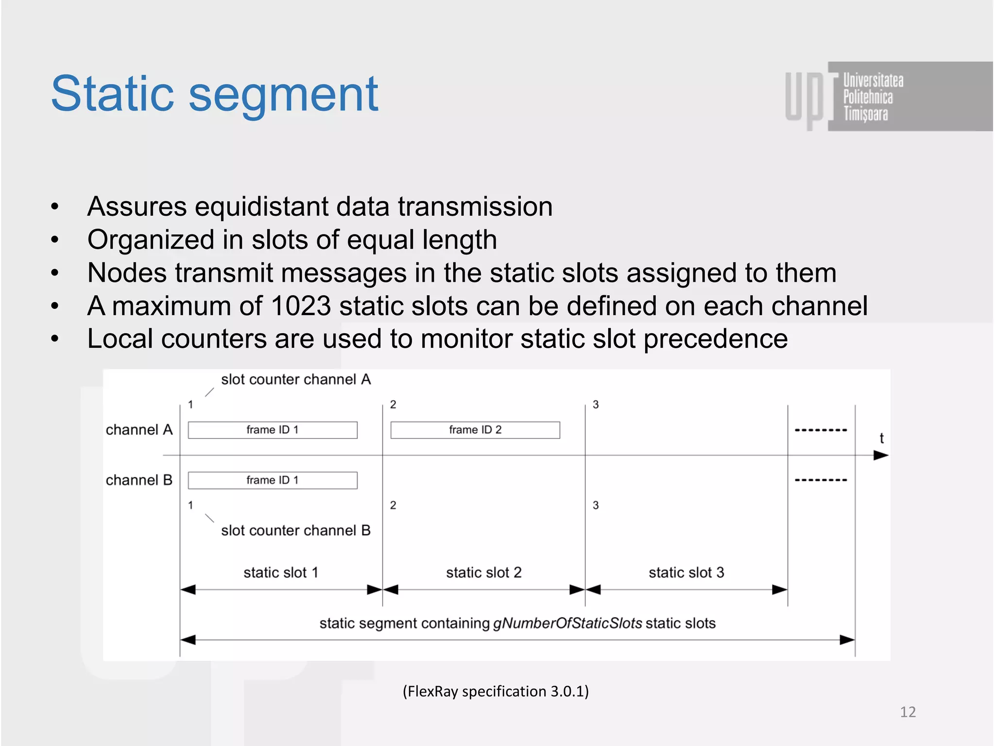
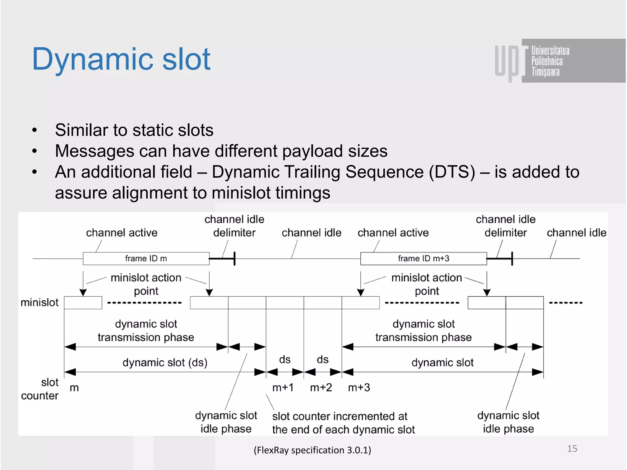
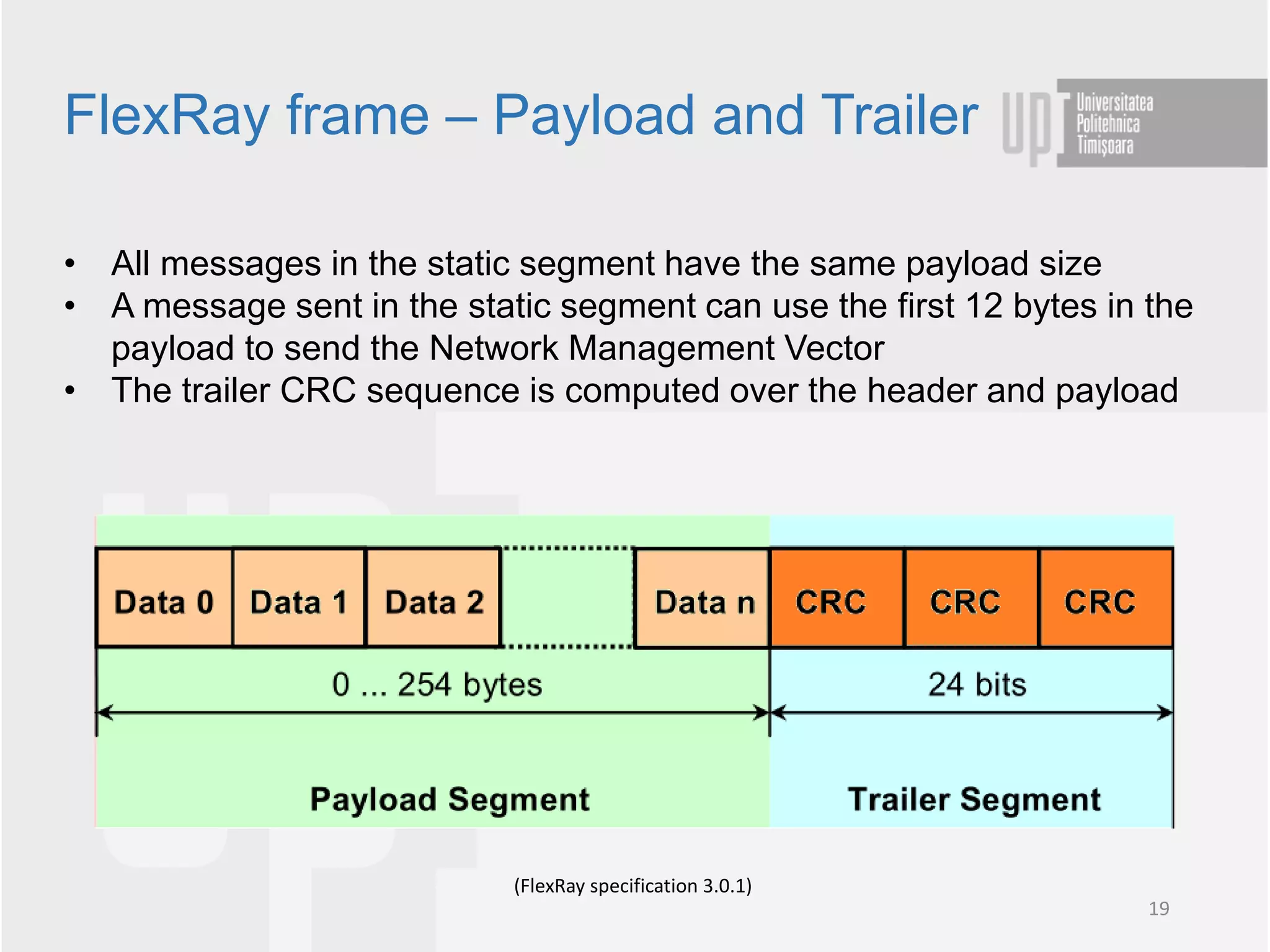
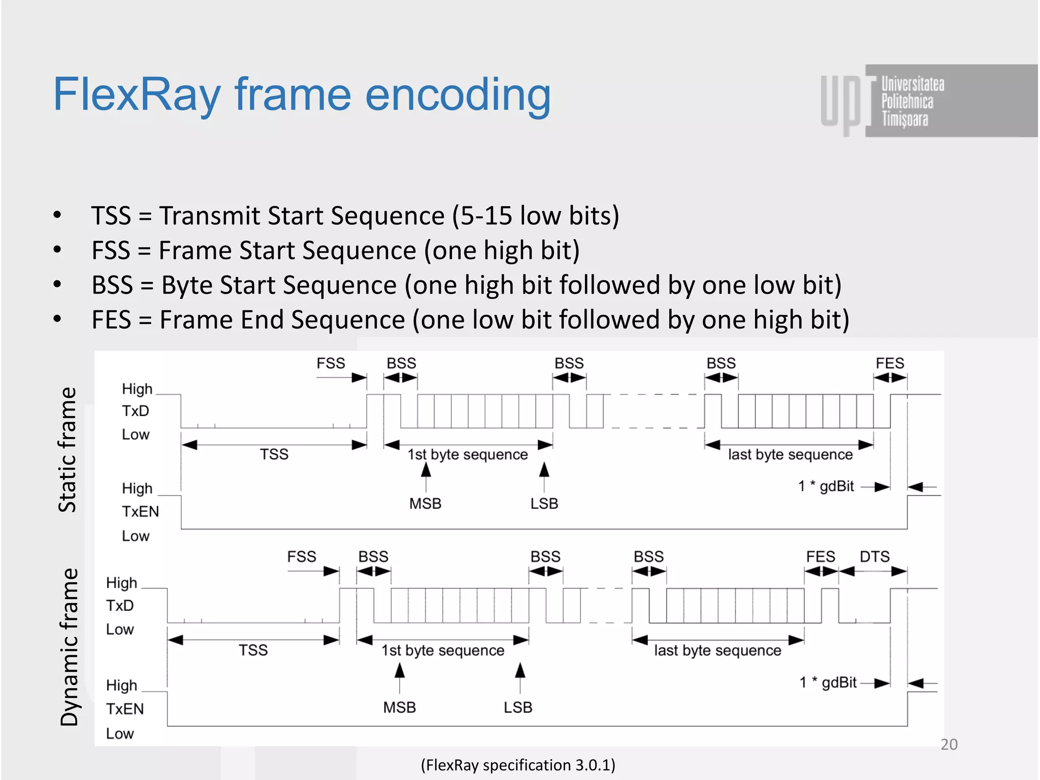
Motivation for developing FlexRay
• Stringent safety, reliability and real-time requirements of the communication
system for safety-critical driver assistance applications
• Although already established in the automotive field, CAN is unable to fulfil
these requirements since it is focused on event-driven communication
• Lack of redundant mechanism to assure fault tolerance
• Communication speed limited to 500kbit/s in series production
• Time-Triggered CAN did not get the expected interest
2
History
• The FlexRay Consortium was founded in 2000 by Daimler Crysler and BMW which
joined with Motorola and Philips to develop a new deterministic and fault tolerant
communication standard
• Version 3.0.1 of the FlexRay specification was published in 2010 and work on the ISO
standardization began
• ISO 17458 (published in 2013) currently provides the FlexRay specification
3
• FlexRay communication can be achieved using different topologies:
line topology, passive/active star topology
• Each FlexRay node has two communication channels to enable
redundancy
• When redundancy is not required channels may be used to increase
data rate to 20Mbit/s
• Based on a time-triggered communication principle
• Optional support for dynamic message transmission
• All communication is performed based on a communication schedule
Communication characteristics
4
• Point-to-point connection
• Line topology
• Passive star topology
Passive network topologies
Node 1 Node 2
Node 1 Node 4
Node 2 Node 3
Node 1 Node 2 Node 3 Node 4
5
• Active star topology
• Derived topologies
• Active star with redundant bus
• Cascaded active star topology
Active network topologies
Node 1 Node 2 Node 3 Node 4
Active star
coupler
Node 1 Node 2 Node 3 Node 4
Active star
Coupler Ch B
Active star
Coupler Ch A
Node 1 Node 2 Node 3 Node 4
Active star
Coupler Ch B
Active star
Coupler Ch A
6
FlexRay OSI layers
• The FlexRay specification covers the Data link and physical layers of the OSI model
• A FlexRay node is consists of an ECU that is connected to the communication line
through a FlexRay controller and two FlexRay transceivers (channel redundancy)
• The controller handles the Data link layer of the FlexRay protocol
• The transceivers is responsible with the physical signalling on the bus
7
• FlexRay uses differential signal transmission and NRZ encoding
• Two communication lines: Bus Plus (BP) and Bus Minus (BM)
• Termination registers with values between 80 and 110 ohm must be
used
• The physical layer defines four bus levels
• Dominant – differential voltage not equal to 0 V (Data_1, Data_0)
• Recessive – differential voltage of 0V (Idle & low power)
FlexRay bus
8
• FlexRay uses two methods for granting bus access to nodes
• TDMA (Time Division Multiple Access)
• FTDMA (Flexible Time Division Multiple Access)
• The TDMA method uses a communication schedule which is split into
time slots
• Each FlexRay node has one or more slots assigned in which it is
granted access to the bus
• The communication schedule is repeated periodically by all nodes
• The FTDMA method is used to implement a dynamic segment which
reserves a specific slot in the communication cycle that can be used
by any node to transmit messages in a non-deterministic manner
Bus access principle
9
• A communication cycle must consist of at least two time segments:
static segment and network idle time (NIT)
• Optional segments: dynamic segment and symbol window
Communication cycle
(After FlexRay specification 3.0.1)
10
• Macroticks
• A communication cycle consists of an integer number of macroticks
• Established as a result of the cluster-wider clock synchronization
• Always consist of an integer number of microticks
• Microticks
• Derived from the internal node oscillator
• Node’s internal time granularity
Timing hierarchy
(After FlexRay specification 3.0.1)
11
• Assures equidistant data transmission
• Organized in slots of equal length
• Nodes transmit messages in the static slots assigned to them
• A maximum of 1023 static slots can be defined on each channel
• Local counters are used to monitor static slot precedence
Static segment
(FlexRay specification 3.0.1)
12
• The length of a static slot is determined by
• The longest FlexRay message
• Largest transmission delay (up to 2,5 µs)
• Clock skew between nodes
• A static slot consists of four segments: Action Point Offset, FlexRay
Frame, Channel Idle Delimiter (11 recessive bits) & Channel Idle
Static slot
(FlexRay specification 3.0.1)
13
• Used to transmit on-event messages
• Always has the same length and follows the static segment
• Also based on a schedule but transmission is done only if the
corresponding events occur
• Split in minislots which are occupied by Dynamic slots used to send
messages until no space is left to send other dynamic messages
Dynamic segment
(FlexRay specification 3.0.1)
14
• Similar to static slots
• Messages can have different payload sizes
• An additional field – Dynamic Trailing Sequence (DTS) – is added to
assure alignment to minislot timings
Dynamic slot
(FlexRay specification 3.0.1) 15
• Used to transmit special bit patterns called symbols
• Symbols are used for establishing communication and network
maintenance
• Flexray Symbols:
• Collision avoidance symbol – used by coldstart nodes to start
communication
• Media test symbol – used to test the bus guardian
• Wake-up symbol – used to initiate the wake-up process
Symbol window
(FlexRay specification 3.0.1) 16
• Consists of three parts: header, payload and trailer
FlexRay frame
(FlexRay specification 3.0.1)
17
FlexRay frame - Header
• Indicator bits – specify the message type
• Startup frame indicator – sent in the static segment as a startup frame
• Sync frame indicator – sent in the static segment for synchronization
• Null frame indicator – specifies if payload is valid or not
• Payload Preamble Indicator – specifies if a network management vector is sent in the
payload
• ID – Frame identifier
• Payload length – in words up to 127 → up to 254 bytes
• CRC – Computed over the ID, payload length and some indicator bits
• Cycle count – the current communication cycle count (counts up to 63)
(FlexRay specification 3.0.1)
18
FlexRay frame – Payload and Trailer
• All messages in the static segment have the same payload size
• A message sent in the static segment can use the first 12 bytes in the
payload to send the Network Management Vector
• The trailer CRC sequence is computed over the header and payload
(FlexRay specification 3.0.1)
19
FlexRay frame encoding
• TSS = Transmit Start Sequence (5-15 low bits)
• FSS = Frame Start Sequence (one high bit)
• BSS = Byte Start Sequence (one high bit followed by one low bit)
• FES = Frame End Sequence (one low bit followed by one high bit)
(FlexRay specification 3.0.1)
20
Static
frame
Dynamic
frame
• Synchronization required to assure reliable FlexRay communication
• Communication cycles and slots must begin at the designated time
and should always have the same length
• FlexRay nodes regularly correct their local clocks :
• Phase or offset correction
• Frequency or rate correction
FlexRay synchronization
(FlexRay specification 3.0.1)
21

FlexRay.pdf

  • 2.
    Motivation for developingFlexRay • Stringent safety, reliability and real-time requirements of the communication system for safety-critical driver assistance applications • Although already established in the automotive field, CAN is unable to fulfil these requirements since it is focused on event-driven communication • Lack of redundant mechanism to assure fault tolerance • Communication speed limited to 500kbit/s in series production • Time-Triggered CAN did not get the expected interest 2
  • 3.
    History • The FlexRayConsortium was founded in 2000 by Daimler Crysler and BMW which joined with Motorola and Philips to develop a new deterministic and fault tolerant communication standard • Version 3.0.1 of the FlexRay specification was published in 2010 and work on the ISO standardization began • ISO 17458 (published in 2013) currently provides the FlexRay specification 3
  • 4.
    • FlexRay communicationcan be achieved using different topologies: line topology, passive/active star topology • Each FlexRay node has two communication channels to enable redundancy • When redundancy is not required channels may be used to increase data rate to 20Mbit/s • Based on a time-triggered communication principle • Optional support for dynamic message transmission • All communication is performed based on a communication schedule Communication characteristics 4
  • 5.
    • Point-to-point connection •Line topology • Passive star topology Passive network topologies Node 1 Node 2 Node 1 Node 4 Node 2 Node 3 Node 1 Node 2 Node 3 Node 4 5
  • 6.
    • Active startopology • Derived topologies • Active star with redundant bus • Cascaded active star topology Active network topologies Node 1 Node 2 Node 3 Node 4 Active star coupler Node 1 Node 2 Node 3 Node 4 Active star Coupler Ch B Active star Coupler Ch A Node 1 Node 2 Node 3 Node 4 Active star Coupler Ch B Active star Coupler Ch A 6
  • 7.
    FlexRay OSI layers •The FlexRay specification covers the Data link and physical layers of the OSI model • A FlexRay node is consists of an ECU that is connected to the communication line through a FlexRay controller and two FlexRay transceivers (channel redundancy) • The controller handles the Data link layer of the FlexRay protocol • The transceivers is responsible with the physical signalling on the bus 7
  • 8.
    • FlexRay usesdifferential signal transmission and NRZ encoding • Two communication lines: Bus Plus (BP) and Bus Minus (BM) • Termination registers with values between 80 and 110 ohm must be used • The physical layer defines four bus levels • Dominant – differential voltage not equal to 0 V (Data_1, Data_0) • Recessive – differential voltage of 0V (Idle & low power) FlexRay bus 8
  • 9.
    • FlexRay usestwo methods for granting bus access to nodes • TDMA (Time Division Multiple Access) • FTDMA (Flexible Time Division Multiple Access) • The TDMA method uses a communication schedule which is split into time slots • Each FlexRay node has one or more slots assigned in which it is granted access to the bus • The communication schedule is repeated periodically by all nodes • The FTDMA method is used to implement a dynamic segment which reserves a specific slot in the communication cycle that can be used by any node to transmit messages in a non-deterministic manner Bus access principle 9
  • 10.
    • A communicationcycle must consist of at least two time segments: static segment and network idle time (NIT) • Optional segments: dynamic segment and symbol window Communication cycle (After FlexRay specification 3.0.1) 10
  • 11.
    • Macroticks • Acommunication cycle consists of an integer number of macroticks • Established as a result of the cluster-wider clock synchronization • Always consist of an integer number of microticks • Microticks • Derived from the internal node oscillator • Node’s internal time granularity Timing hierarchy (After FlexRay specification 3.0.1) 11
  • 12.
    • Assures equidistantdata transmission • Organized in slots of equal length • Nodes transmit messages in the static slots assigned to them • A maximum of 1023 static slots can be defined on each channel • Local counters are used to monitor static slot precedence Static segment (FlexRay specification 3.0.1) 12
  • 13.
    • The lengthof a static slot is determined by • The longest FlexRay message • Largest transmission delay (up to 2,5 µs) • Clock skew between nodes • A static slot consists of four segments: Action Point Offset, FlexRay Frame, Channel Idle Delimiter (11 recessive bits) & Channel Idle Static slot (FlexRay specification 3.0.1) 13
  • 14.
    • Used totransmit on-event messages • Always has the same length and follows the static segment • Also based on a schedule but transmission is done only if the corresponding events occur • Split in minislots which are occupied by Dynamic slots used to send messages until no space is left to send other dynamic messages Dynamic segment (FlexRay specification 3.0.1) 14
  • 15.
    • Similar tostatic slots • Messages can have different payload sizes • An additional field – Dynamic Trailing Sequence (DTS) – is added to assure alignment to minislot timings Dynamic slot (FlexRay specification 3.0.1) 15
  • 16.
    • Used totransmit special bit patterns called symbols • Symbols are used for establishing communication and network maintenance • Flexray Symbols: • Collision avoidance symbol – used by coldstart nodes to start communication • Media test symbol – used to test the bus guardian • Wake-up symbol – used to initiate the wake-up process Symbol window (FlexRay specification 3.0.1) 16
  • 17.
    • Consists ofthree parts: header, payload and trailer FlexRay frame (FlexRay specification 3.0.1) 17
  • 18.
    FlexRay frame -Header • Indicator bits – specify the message type • Startup frame indicator – sent in the static segment as a startup frame • Sync frame indicator – sent in the static segment for synchronization • Null frame indicator – specifies if payload is valid or not • Payload Preamble Indicator – specifies if a network management vector is sent in the payload • ID – Frame identifier • Payload length – in words up to 127 → up to 254 bytes • CRC – Computed over the ID, payload length and some indicator bits • Cycle count – the current communication cycle count (counts up to 63) (FlexRay specification 3.0.1) 18
  • 19.
    FlexRay frame –Payload and Trailer • All messages in the static segment have the same payload size • A message sent in the static segment can use the first 12 bytes in the payload to send the Network Management Vector • The trailer CRC sequence is computed over the header and payload (FlexRay specification 3.0.1) 19
  • 20.
    FlexRay frame encoding •TSS = Transmit Start Sequence (5-15 low bits) • FSS = Frame Start Sequence (one high bit) • BSS = Byte Start Sequence (one high bit followed by one low bit) • FES = Frame End Sequence (one low bit followed by one high bit) (FlexRay specification 3.0.1) 20 Static frame Dynamic frame
  • 21.
    • Synchronization requiredto assure reliable FlexRay communication • Communication cycles and slots must begin at the designated time and should always have the same length • FlexRay nodes regularly correct their local clocks : • Phase or offset correction • Frequency or rate correction FlexRay synchronization (FlexRay specification 3.0.1) 21