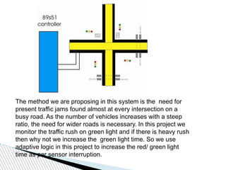
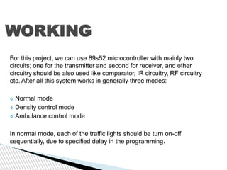
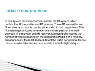
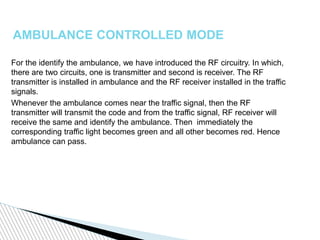
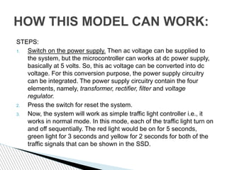
SUBMITTED BY:
AHANA PAL
SWAPNA SHALINI
VINNI
ANKIT GUPTAAnkit Gupta
SMART
TRAFFIC
CONTROLLER
INTRODUCTION
 IN this project we show that how we design a intelligent ambulance
for modern cities. If the road is very much busy with traffic and there
is a heavy jam on the road. Then its possible at that time
ambulance use its special signal to activate the traffic light from red
to green. If in the case of emergency all the ambulance use this
technique then definitely we save many lifes.
 For this project we use two circuit one is transmitter and second is
receiver. In both the circuit we use microcontroller base circuit.
 In this project we use RF communication for data transfer from
ambulance to signal and Infra Red technology for the detect the
rush.
The method we are proposing in this system is the need for
present traffic jams found almost at every intersection on a
busy road. As the number of vehicles increases with a steep
ratio, the need for wider roads is necessary. In this project we
monitor the traffic rush on green light and if there is heavy rush
then why not we increase the green light time. So we use
adaptive logic in this project to increase the red/ green light
time as per sensor interruption.
COMPONENTS USED
 # 8952 Microcontroller
 --To interface all the sensers ,seven segment
 #LM339 OPAMP Comparator & LM 358
Comparator
 --LM339 has 4 comparator
 --LM358 has 2 opamp
 Photodiode
 #Seven Segment Display
- -Used for counters
 IR led
 #LED
--Used for lights in traffic signal
 # Digital RF transmitter
-- For transmitting emergency code in terms of RF
 #Digital RF receiver
--For decoding the emergency code in receiver circuit
 # Counter
--For counting the timers on traffic light
 # Sensor
 Variable resistor
 Voltage regulator
 Ship resistor
CIRCUIT DIAGRAM OF PROJECT
TRANSMITTER CIRCUIT
POWER SUPPLY
230 V AC
50 Hz
5V
DC
9V step down
transformer
Filter(470µf)
5v RegulatorBridge rectifier
WORKING
For this project, we can use 89s52 microcontroller with mainly two
circuits; one for the transmitter and second for receiver, and other
circuitry should be also used like comparator, IR circuitry, RF circuitry
etc. After all this system works in generally three modes:
 Normal mode
 Density control mode
 Ambulance control mode
In normal mode, each of the traffic lights should be turn on-off
sequentially, due to specified delay in the programming.
DENSITY CONTROL MODE
In this system the microcontroller control the IR system, which
contain the IR transmitter and IR receiver. These IR transmitter and
IR receiver are mounted on the either side of road respectively. This
IR system get activated whenever any vehicle pass on the road
between IR transmitter and IR receiver. Microcontroller counts the
number of vehicle passing on the road and stored it in the memory.
Simultaneously, these IR sensors detect the traffic congestion. Hence
microcontroller take decision and update the traffic light delays.
AMBULANCE CONTROLLED MODE
For the identify the ambulance, we have introduced the RF circuitry. In which,
there are two circuits, one is transmitter and second is receiver. The RF
transmitter is installed in ambulance and the RF receiver installed in the traffic
signals.
Whenever the ambulance comes near the traffic signal, then the RF
transmitter will transmit the code and from the traffic signal, RF receiver will
receive the same and identify the ambulance. Then immediately the
corresponding traffic light becomes green and all other becomes red. Hence
ambulance can pass.
HOW THIS MODEL CAN WORK:
STEPS:
1. Switch on the power supply. Then ac voltage can be supplied to
the system, but the microcontroller can works at dc power supply,
basically at 5 volts. So, this ac voltage can be converted into dc
voltage. For this conversion purpose, the power supply circuitry
can be integrated. The power supply circuitry contain the four
elements, namely, transformer, rectifier, filter and voltage
regulator.
2. Press the switch for reset the system.
3. Now, the system will work as simple traffic light controller i.e., it
works in normal mode. In this mode, each of the traffic light turn on
and off sequentially. The red light would be on for 5 seconds,
green light for 3 seconds and yellow for 2 seconds for both of the
traffic signals that can be shown in the SSD.
4. Now, if the number of vehicle is start to increase i.e., rush of the
respective
road increases, by which the sensors are activated.
 If only one sensor is activated, then there is no affect to the counter of
ssd.
 If two sensors are activated, then delay of the green light is increased
by 2 and red light is increased by 2 seconds of other signal.
 If three sensors are activate, then further delay will be increased by 2.
5. If the red light of particular traffic signal is on and by chances the
ambulance comes near that traffic signal, then the switch can be
pressed from the ambulance, then after one complete cycle ( from red
to green), that signal should become green until the switch can be
released.
Tlc.finalppt

Tlc.finalppt

  • 1.
    SUBMITTED BY: AHANA PAL SWAPNASHALINI VINNI ANKIT GUPTAAnkit Gupta SMART TRAFFIC CONTROLLER
  • 2.
    INTRODUCTION  IN thisproject we show that how we design a intelligent ambulance for modern cities. If the road is very much busy with traffic and there is a heavy jam on the road. Then its possible at that time ambulance use its special signal to activate the traffic light from red to green. If in the case of emergency all the ambulance use this technique then definitely we save many lifes.  For this project we use two circuit one is transmitter and second is receiver. In both the circuit we use microcontroller base circuit.  In this project we use RF communication for data transfer from ambulance to signal and Infra Red technology for the detect the rush.
  • 3.
    The method weare proposing in this system is the need for present traffic jams found almost at every intersection on a busy road. As the number of vehicles increases with a steep ratio, the need for wider roads is necessary. In this project we monitor the traffic rush on green light and if there is heavy rush then why not we increase the green light time. So we use adaptive logic in this project to increase the red/ green light time as per sensor interruption.
  • 4.
    COMPONENTS USED  #8952 Microcontroller  --To interface all the sensers ,seven segment  #LM339 OPAMP Comparator & LM 358 Comparator  --LM339 has 4 comparator  --LM358 has 2 opamp  Photodiode  #Seven Segment Display - -Used for counters  IR led  #LED --Used for lights in traffic signal
  • 5.
     # DigitalRF transmitter -- For transmitting emergency code in terms of RF  #Digital RF receiver --For decoding the emergency code in receiver circuit  # Counter --For counting the timers on traffic light  # Sensor  Variable resistor  Voltage regulator  Ship resistor
  • 6.
  • 7.
  • 8.
    POWER SUPPLY 230 VAC 50 Hz 5V DC 9V step down transformer Filter(470µf) 5v RegulatorBridge rectifier
  • 9.
    WORKING For this project,we can use 89s52 microcontroller with mainly two circuits; one for the transmitter and second for receiver, and other circuitry should be also used like comparator, IR circuitry, RF circuitry etc. After all this system works in generally three modes:  Normal mode  Density control mode  Ambulance control mode In normal mode, each of the traffic lights should be turn on-off sequentially, due to specified delay in the programming.
  • 10.
    DENSITY CONTROL MODE Inthis system the microcontroller control the IR system, which contain the IR transmitter and IR receiver. These IR transmitter and IR receiver are mounted on the either side of road respectively. This IR system get activated whenever any vehicle pass on the road between IR transmitter and IR receiver. Microcontroller counts the number of vehicle passing on the road and stored it in the memory. Simultaneously, these IR sensors detect the traffic congestion. Hence microcontroller take decision and update the traffic light delays.
  • 11.
    AMBULANCE CONTROLLED MODE Forthe identify the ambulance, we have introduced the RF circuitry. In which, there are two circuits, one is transmitter and second is receiver. The RF transmitter is installed in ambulance and the RF receiver installed in the traffic signals. Whenever the ambulance comes near the traffic signal, then the RF transmitter will transmit the code and from the traffic signal, RF receiver will receive the same and identify the ambulance. Then immediately the corresponding traffic light becomes green and all other becomes red. Hence ambulance can pass.
  • 12.
    HOW THIS MODELCAN WORK: STEPS: 1. Switch on the power supply. Then ac voltage can be supplied to the system, but the microcontroller can works at dc power supply, basically at 5 volts. So, this ac voltage can be converted into dc voltage. For this conversion purpose, the power supply circuitry can be integrated. The power supply circuitry contain the four elements, namely, transformer, rectifier, filter and voltage regulator. 2. Press the switch for reset the system. 3. Now, the system will work as simple traffic light controller i.e., it works in normal mode. In this mode, each of the traffic light turn on and off sequentially. The red light would be on for 5 seconds, green light for 3 seconds and yellow for 2 seconds for both of the traffic signals that can be shown in the SSD.
  • 13.
    4. Now, ifthe number of vehicle is start to increase i.e., rush of the respective road increases, by which the sensors are activated.  If only one sensor is activated, then there is no affect to the counter of ssd.  If two sensors are activated, then delay of the green light is increased by 2 and red light is increased by 2 seconds of other signal.  If three sensors are activate, then further delay will be increased by 2. 5. If the red light of particular traffic signal is on and by chances the ambulance comes near that traffic signal, then the switch can be pressed from the ambulance, then after one complete cycle ( from red to green), that signal should become green until the switch can be released.