IRJET-Design and Implementation of Automatic Dual Axis Solar Tracking System
Automated cornering headlamp technical report
1. 1
Design and Development of an Automated Cornering Headlamp
Mohd Amirul Bin Azmi1
, Norzalina Binti Othman2
EEA Section, University Kuala Lumpur Malaysia Spanish Institute, Kulim Hi-Tech Park, 09000 Kulim Kedah, Malaysia
Abstract
Nowadays the growth of advanced technology of adaptive front headlamp system in the automotive industry is increasing rapidly from
time to time by means applying an advanced electronic control system method. One of these controlling methods that apply this
advanced electronic control system is an automated cornering headlamp. This cornering headlamp uses an advanced integrated circuit as
its controller unit. It controls the direction of the headlamp illumination projection at the bending road in its basic application. Besides
that, it adjusts illumination projection to prevent glare problems. It uses angular measurement sensor or angular potentiometer that is
placed at the steering shaft to detect the angle of the steering and adjusts the headlamp projection at the suitable angle to illuminate
bending road to prevent accident happen.
Keywords: Automated Cornering Headlamp.
1. Introduction
When driving a vehicle, the most important thing that should be consider is the visual of the driver. This visual one of
the important aspect while driving as it consists about 85% of the vehicle behavior. Safe driving depends on driver ability
to notice many things at once while driving a vehicle. Driver behavior represents a predominant cause, contribute over
90% of crashes. When it comes to driving a vehicle on the nighttime, an adequate lighting is required to see the variety of
the objects on the road such as incoming vehicle, traffic control device, pedestrians and the other potentials that can cause
an accident. However, when the vehicle at the cornering state, the driver cannot detect or see what is the expected vehicle,
object or pedestrians at the bending road. The headlamp is design to illuminate the road at the vertical state, but it cannot
illuminate the road on the cornering state. To overcome this problem, the development of an automatic cornering headlamp
system will be needed. An automatic cornering headlamp system is a system that used a rotary sensor that was attached at
the steering shaft to detect or sense the changes of the angle of the steering and adjust the headlamp according to the angle
of steering deflection.
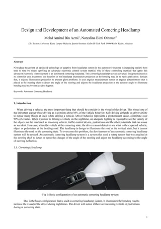
1.1. Cornering Headlamp
Fig 1: Basic configuration of an automatic cornering headlamp system
This is the basic configuration that is used in cornering headlamp system. It illuminates the bending road to
increase the visual of the driver during nighttimes. The driver will notice if there are incoming vehicle or pedestrians
during at cornering state.
2. 2
2. Literature Review
2.1 Modular Lightning System and Method
Today technologies that used for this system just only discuss about other problem such as the motor problem that
not following the signal of the microcontroller, the problem of the motor not functioning accurately and the type of the
mounting of the bulb that used and the other advances technologies that have been developed by many automotive
companies worldwide. In the preview of the headlamp system that has been done by (William F. Budnovitch and
Mahendra K. Patel 1993), they only focusing on the headlamp reflector design to focused the illumination of the filament
bulb. The reflector has been design to integrate the illumination and increase the view of the driver. The integration of the
reflector only increase very small amount of the illumination instead of the integration of the lamp or the bulb that will
increase the illumination drastically. Figure 2 show the integration of the lamp reflector of the automatic cornering
headlamp.
Fig 2 : The integration of the lamp reflector
2.2 Headlamp for Cornering Operation.
Cornering system has its own operation to move from the steering angle. Base on the preview of headlamp for
cornering operation that has been done by (Tsuneo Sekiguchi and Koichi Nagano 1992), they state that the correct
variation of a property of light orientation induced by the inclination of a vehicle body during a cornering operation. A
projector type cornering headlamp including an inclination sensor will be used to project the movement of the headlamp
angle. The move of the headlamp angle is base on the inclination sensor signal that has been calculated and process by the
microcontroller. Figure 3 the cornering headlight base on inclination sensor.
Fig 3 : The cornering headlight base on inclination sensor
3. 3
2.3 Comparison between Light Sources
The uses of the light source are the most major part of the headlamp in cornering system. Driver needs the clearest
view to make the right decision to prevent accident happen. Based on the figure 4, it shows that the comparison of different
lamps effect the luminance of the light. According to the journal xenon and/or LEDs at headlamps that have been done by
(Csaba Blaga 2011), he state that Led is the promising light source than other type of lamps because it has the best
specification as the light spectrum, efficiency, life time, communication and price. The luminance of the headlamp will
affect the driver vision, thus it will determine the decision making of the driver to increase the driving determination.
Fig 4 : The comparison of different lamps
2.4 Cornering Electronic Control
The component need to be choose to make sure right control of the cornering headlamp to be execute by the
controller. A thesis of an automatic cornering headlamp system that has been done by (Jack L Owings 1962) that covered
the design, parameters and the selection of the components of the system. In his thesis, it was a design that used to control
the movement of the headlamp angle and the headlamp switching of the bridged terminal. For the selection of the
headlamp, the usage of the HID and LED light is much better than the filament headlamp because the HID and the LED
light illuminating the road at night better and providing good quality light pattern.
Fig 5 : The Cornering Headlamp Bridge Electronic Circuit
4. 4
3. Methodology
The common method that has been used consist of five (5) basic steps that are research phase, component
identification and circuit design, mechanical part design, programming phase and troubleshooting.
Fig 6 : The Angular Measurement and Light Dependent Resistor Sensor.
3.1 Project Flow Chart
Angular
measurement
detection
Incoming vehicle
illumination
detection
6. 6
No of LED Columns Voltage Steering Angle (ᵒ) Headlamp Angle (ᵒ)
1 2.5 V 90 Degree 90 Degree
2 2.5 V 90 Degree 100 Degree
3 2.5 V 90 Degree 110 Degree
4 2.5 V 90 Degree 120 Degree
5 1.9 V 120 Degree 140 Degree
6 1.3 V 140 Degree 150 Degree
7 0.6 V 180 Degree 160 Degree
8 0.1 V 240 Degree 170 Degree
Table 1 : Result of Steering angle vs Headlamp Angle
Fig 8 : Right Headlamp
No of LED Columns Voltage Steering Angle (ᵒ) Headlamp Angle (ᵒ)
1 2.5 V 90 Degree 90 Degree
2 2.5 V 90 Degree 80 Degree
3 2.5 V 90 Degree 70 Degree
4 2.5 V 90 Degree 60 Degree
5 3.1 V 60 Degree 40 Degree
6 3.8 V 40 Degree 30 Degree
7 4.4 V 0 Degree 20 Degree
8 5 V -60 Degree 10 Degree
Table 2 : Result of Steering angle vs Headlamp Angle
At the first position of the automatic cornering headlamp, the position of the headlamp angle is at 90 degree. Then
when the steering has been turn to its position, the angular measurement potentiometer will sent the signal from the
following angle that has been set. In this typical project, there are 2 sets of the angle acting in both headlamps. For initial
position of the headlamps, it has been set up to 90 degree for the both of the headlamp illumination because of the steering
position angle in 90 degree. At the left headlamp, when the steering angle has been set to 90 degree, the first column of the
LED has been set to 90 degree. The second column of the LED will be set to 100 degree, third column will be set to 110
degree and the fourth column will be set to the 120 degree. Then when the steering has been turn to 120 degree, the fifth
column of LED will illuminate at 140 degree. For the sixth column of LED at 150 degrees when the steering angle
reaching 140 degree. Then for the seventh column of LED at 160 degree when steerig angle at 180 degree and eighth
column of LED at 170 degree when the steering angle at 240 degree. Same operation occurs at the right headlamp. But the
angle of the steering and the illumination angle of the LED are opposite direction to the left headlamp. The column of the
LED for the first, second, third, fourth, fifth, sixth, seventh and eighth at 90, 80, 70, 60, 40, 30, 20, and 10 degree when the
angle of the steering reaching 90, 60, 40, 0, and -60 degree.
7. 7
Chart 1 : Meter vs. Illumination (LUX) Chart 2 : Illumination (LUX) vs. Resistance
All of the LED illumination been control at state high or low according to the value of the LUX of illumination
from oncoming vehicle. The value of the illumination LUX will change when the distance of the vehicle change. In this
typical project, the distance of the vehicle has been taken from 1 meter to 20 meters. When the distance of the vehicle
illumination decreasing, the value of the illumination LUX will increasing. This is how the LDR sensor detects the
illumination of the oncoming vehicle by valuing the illumination LUX and chooses either it needs to be high or lower the
headlamp illumination.
5. Conclusion
By using Light Emitting Diode (LED) as the major part of the headlamp is an attractive and effective way instead of
using halogen bulb and xenon bulb because of its low cost, high in freedom of designers, simple structure, high efficiency,
high in life time and low of energy consumption. Nowadays, automobile start to use light emitting diode (LED) as their
illumination projection of headlamp because of its advantages. From this project, using running light for automatic
cornering system method instead of using motor for the angle projection also give same illumination projection.
Furthermore, it’s decreasing the cost of nowadays cornering headlamp that using motor for its functional.
Acknowledgements
Alhamdulillah thanks to Allah S.W.T, The Most merciful and the Most Gracious for His willing and blessing for
allowing me to finish my Final Year Project Thesis. First and foremost, praise to Allah for His wisdom and blessing for
giving me the strength and patience to complete my Final Year Project. I would like to express my deepest gratitude to my
supervisor, Mdm Norzalina Bt Hj Othman, for her valuable guidance, advices, tolerance and patience towards supporting
me in preparing this project throughout the semester. I truly appreciate the guidance, support and her willingness to take
time to discuss about my project`s research. Again, thank you for treating me with respect and timely advice throughout
my graduate studies and giving me the opportunity to develop and apply my skills as an engineering student.
References
[1] Patel, M. K., Lake, W., Luciano, L. W., Lighting, D., Kansas, N., & Cole, P. E. R. (1993) Modular Lightning system and method.
Retrieved from http://www.googlescholar.com
[2] Nagano, K., Suzuki, S., & Company, S. E. (1992). Head lamp for cornering operation. 5,161,875.
Retrieved from http://www.googlescholar.com
[3] Blaga, C. (n. d.). XENON AND/OR LEDs AT HEADLAMPS, 78-81
Retrieved from http://www.googlescholar.com
[4] Jack, L., Owings, J. L., & Ave, L. (1962). Cornering Lights United State Patent, 23-25.
Retrieved from http://www.googlescholar.com
[5] Wsrdenweber, B., Labahn, N., & Hueck, H. K. G. (1995). HEADLAMP-BASED VISION SYSTEM AND THE VISION TASK
Retrieved from http://www.googlescholar.com
[6] Hiromi Shibata, Kazuki Takahashi, Keiichi Tajima (1990, October 16). Vehicle Cornering Headlamp System.
Retrieved from http://www.googlescholar.com
[7] Wu, W., Hong, T., Chileshe, J. M., Chen, C., Guo, J., & Zeng, Z. (2011). Research of Dynamic Steering Headlamps System Based
on LIN Bus. Journal of Computer, 6(12), 2607-2614.
-500
0
500
1000
1500
2000
2500
0 5 10 15 20 25
Illumination(LUX)
Meter