This circuit uses light dependent resistors and a timer integrated circuit to automatically turn on a white LED night lamp when it gets dark and turn it off in the morning when light is detected. It also uses another light dependent resistor and transistor circuit to generate a morning alarm melody when light is detected. The circuit is powered by a 9V transformer with battery backup and provides both automatic night lighting and a morning alarm function.
This is simple yet powerful concept, which uses transistor as a switch.
By using this system manual work could be reduced.
Energy consumption is reduced.
Automatically switches ON lights when the sunlight goes below the visible region of our eyes.
Automatically switches OFF lights whenever the sunlight comes and activates the morning alarmIn this busy world, minimizing the effort and time is the ultimate aim of technology.
Now-a-days manually operated street lights are not switched OFF even when the sunlight comes and also switched ON earlier before sunset.
No need to set the time.
Automatic street light using LDR and TransistorHimanshiSingh71
It glows during night and switches off automatically as the sun rises. Street light which automatically gets turned on in the night and gets turned off in the morning or day time, there are sensors who senses the light and control the light accordingly.
Automatic emergency light using led pptRitik Joshi
its a power point presentation on automatic emergency light using led with complete details of the circuit & the components used to make it along with the advantages, disadvantages & future scope. The slides also contains pcb layout of the circuit.
Many of the people have a phobia of darkness, so to assist them in such situation, we have explained a simple circuit. It will automatically turn on street light in the way of LEDs or bulb coupled with relay. Working this circuit is very much easy and also the power consumed by the circuit is very low because of the very few components used in the circuit.
A Measurements Project on Light Detection sensorsvrohith 9
The main aim of this project is to saving system with LDR this is to save the power. We want to save power automatically instead of doing manual. So it’s easy to cost effectiveness. This saved power can be used in some other cases. So in villages, towns etc. we can design intelligent systems for the usage of light or we can also use this to reduce the electricity bill of our home. This project can also be used for security of the houses, banks, etc.
AUTOMATIC LIGHT & DARK SENSING SYSTEM WITH MOSQUITO REPELLENT CIRCUITShahrukh Javed
DESCRIPTION
It is a simple and powerful concept, which uses transistor (BC 547) as a switch to switch ON and OFF the light automatically & a Light Dependent Resistors (LDR) which senses the light, made from a piece of exposed semiconductor material i.e cadmium sulphide, that changes its electrical resistance from several thousand Ohms in the dark to only a few hundred Ohms, when light hits the device, the photons give electrons energy by creating hole-electron pairs in the material. This makes them jump into the conductive band and thereby conduct electricity.
The circuit automatically switches ON lights when the light goes below the visible region & automatically switches OFF lights when light fall on it, by using a sensor which senses the light just like our eyes.
Also, the circuit has a long response time requiring many seconds to respond to a change in the light intensity.
TEAM MEMBER
SHAHRUKH JAVED
MOHAMMED HASSAN M
For more log on to: http://shahrukhjaved.webs.com/apps/blog/
E-mial: shahrukh.tjit14@gmail.com
My new upload !!! --> http://www.slideshare.net/choleraparth91/smart-vehicle-ensuring-safe-ride-using-accerolometer-laser-sensor-co-sensor-and-also-with-use-of-gsm-modem-and-solar-panel
Contact & follow me to get PDF & PPT file - https://www.linkedin.com/in/parthcholera/
Email me directly if you want these file !!
choleraparth91@yahoo.com
or
contact me on fb - https://www.facebook.com/choleraparth91
or
https://www.facebook.com/Textivity
or
message me on - 08097508067
I suggest to go for these project !!! :D :D
This security project is able to protect your house balcony or loggia by means of an optical path. This laser beam is almost invisible. The beam or light ray of Laser pointer should be pointed directly to a mirror fixed on the front wall . The reflected light ray should fall on surface of the LDR. The alarm system consists of two main sections : the transmitter (laser pointer) and the receiver (LDR)
Presentation on Electronic Eye controlled Security SystemSagar Magarde
Electronic eye is also called magic eye. As the automation is emerging technology these days.
Just imagine a door bell that automatically rings when a person visit your home. This also provides security when any person is trying to enter into your home without your permission.
Electronic eye is the electronic device that continuously watches if anyone is visiting your home.
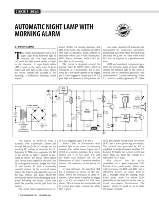
1. C I I R U IU IIT EIAD E A S
C RC C T D S
AUTOMATIC NIGHT LAMP WITH SAN
I THE
O
MORNING ALARM
D. MOHAN KUMAR sistors (LDRs) for sensing darkness and Low-value capacitor C2 maintains the
light in the room. The resistance of LDR is monostable for continuous operation,
T
his circuit automatically turns on a very high in darkness, which reduces to eliminating the timer effect. By increasing
night lamp when bedroom light is minimum when LDR is fully illuminated. the value of C2, the ‘on’ time of the white
switched off. The lamp remains LDR1 detects darkness, while LDR2 de- LED can be adjusted to a predetermined
‘on’ until the light sensor senses daylight tects light in the morning. time.
in the morning. A super-bright white The circuit is designed around the LDR2 and associated components gen-
LED is used as the night lamp. It gives popular timer IC NE555 (IC2), which is erate the morning alarm at dawn. LDR2
bright and cool light in the room. When configured as a monostable. IC2 is acti- detects the ambient light in the room at
the sensor detects the daylight in the vated by a low pulse applied to its trigger sunrise and its resistance gradually falls
morning, a melodious morning alarm pin 2. Once triggered, output pin 3 of IC2 and transistor T1 starts conducting. When
sounds. goes high and remains in that position un- T1 conducts, melody-generator IC UM66
The circuit is powered from a til IC2 is triggered again at its pin 2. (IC3) gets supply voltage from the emitter
standard 0-9V transformer. Diodes D1 When LDR1 is illuminated with of T1 and it starts producing the melody.
through D4 rectify the AC voltage and the ambient light in the room, its resistance The musical tone generated by IC3 is
resulting DC voltage is smoothed by C1. remains low, which keeps trigger pin 2 amplified by single-transistor amplifier T2.
Regulator IC 7806 gives regulated 6V DC of IC2 at a positive potential. As a result, Resistor R7 limits the current to IC3 and
to the circuit. A battery backup is pro- output pin 3 of IC2 goes low and zener diode ZD limits the voltage to a
vided to power the circuit when mains the white LED remains off. As the safer level of 3.3 volts.
fails. When mains supply is available, the illumination of LDR1’s sensitive window The circuit can be easily
9V rechargeable battery charges via diode reduces, the resistance of the device in- assembled on a general-purpose PCB.
D5 and resistor R1 with a reasonably creases. Enclose it in a good-quality plastic case
constant current. In the event of mains In total darkness, the specified LDR with provisions for LDR and LED. Use a
failure, the battery automatically takes up has a resistance in excess of 280 kilo- reflective holder for white LED to
the load without any delay. Diode D5 ohms. When the resistance of LDR1 in- get a spotlight effect for reading. Place
prevents the battery from discharging back- creases, a short pulse is applied to trigger LDRs away from the white LED,
wards following the mains failure and pin 2 of IC2 via resistor R2 (150 kilo- preferably on the backside of the case, to
diode D6 provides current path from the ohms). This activates the monostable and avoid unnecessary illumination. The
battery. its output goes high, causing the white speaker should be small so as to make
The circuit utilises light-dependant re- LED to glow. the gadget compact.
ELECTRONICS FOR YOU DECEMBER 2003