This document describes an automated car wash system designed and simulated using RSLogics 5000 PLC software. The system was divided into two zones - zone 1 for presoak, foam application, and scrubbing, and zone 2 for rinsing, waxing, and drying. Cars arrive randomly and the program can speed up operations if there is a long queue. Zone 1 performs its operations then waits for zone 2 to indicate it is ready before moving the car. Once operations in both zones are complete, the car is moved out and the number of cars washed is displayed. Challenges included understanding program scan order and adding structured text for zone 2 operations. Ladder logic diagrams show the logic for zone 1 and 2 operations
In this document
Powered by AI
Introduction to the automated car wash project designed using RSLOGICS 5000, including the system zones for operations.
Details the operational flow for Zone 1 (pre-soak, foam, scrub) and Zone 2 (rinse, wax, dry) including system checks and queue management.
Faced challenges understanding program scans and control shifts affecting the random car generator.
Main routine ladder diagram showcasing operations in Zone 1, including start conditions and car arrival queue.
Continues the main routine with checks for car queue management, entrance gate operation, and subroutine shifts.
Further progress on execution with sequence operations in Zone 1 and managing car movements.
Belt control logic to manage car entry and exit from Zone 1, ensuring operations run smoothly.
Subroutines for executing individual operations: presoak, foam application, and their controls.
Detailed foam application operations with timing controls based on queue status.
Scrubber operations and related controls marking the end of Zone 1.
Initiation of Zone 2 operations (rinse, wax, dry) and inter-zone communication with updates on washes.Waxes and dries operations, utilizing timers and mode checks while marking operational achievements.
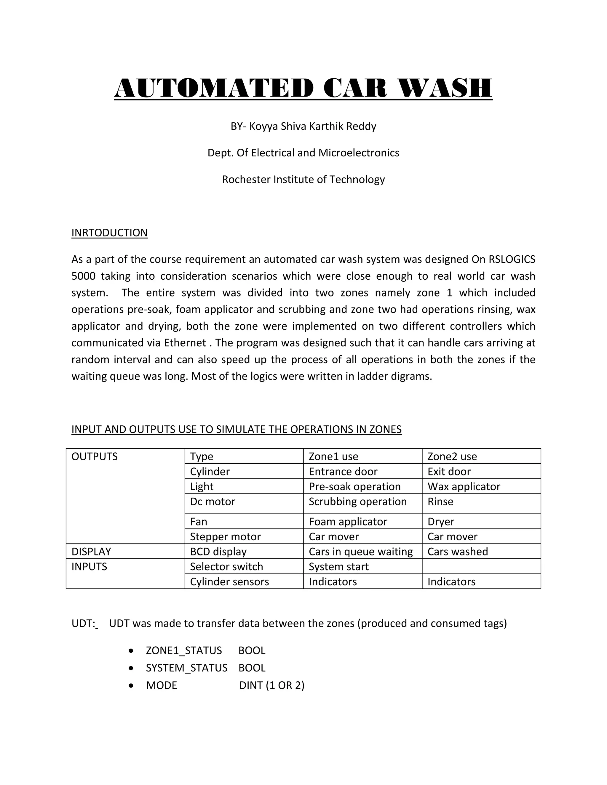
AUTOMATED CAR WASH
BY-Koyya Shiva Karthik Reddy
Dept. Of Electrical and Microelectronics
Rochester Institute of Technology
INRTODUCTION
As a part of the course requirement an automated car wash system was designed On RSLOGICS
5000 taking into consideration scenarios which were close enough to real world car wash
system. The entire system was divided into two zones namely zone 1 which included
operations pre-soak, foam applicator and scrubbing and zone two had operations rinsing, wax
applicator and drying, both the zone were implemented on two different controllers which
communicated via Ethernet . The program was designed such that it can handle cars arriving at
random interval and can also speed up the process of all operations in both the zones if the
waiting queue was long. Most of the logics were written in ladder digrams.
INPUT AND OUTPUTS USE TO SIMULATE THE OPERATIONS IN ZONES
OUTPUTS Type Zone1 use Zone2 use
Cylinder Entrance door Exit door
Light Pre-soak operation Wax applicator
Dc motor Scrubbing operation Rinse
Fan Foam applicator Dryer
Stepper motor Car mover Car mover
DISPLAY BCD display Cars in queue waiting Cars washed
INPUTS Selector switch System start
Cylinder sensors Indicators Indicators
UDT: UDT was made to transfer data between the zones (produced and consumed tags)
ZONE1_STATUS BOOL
SYSTEM_STATUS BOOL
MODE DINT (1 OR 2)
2.
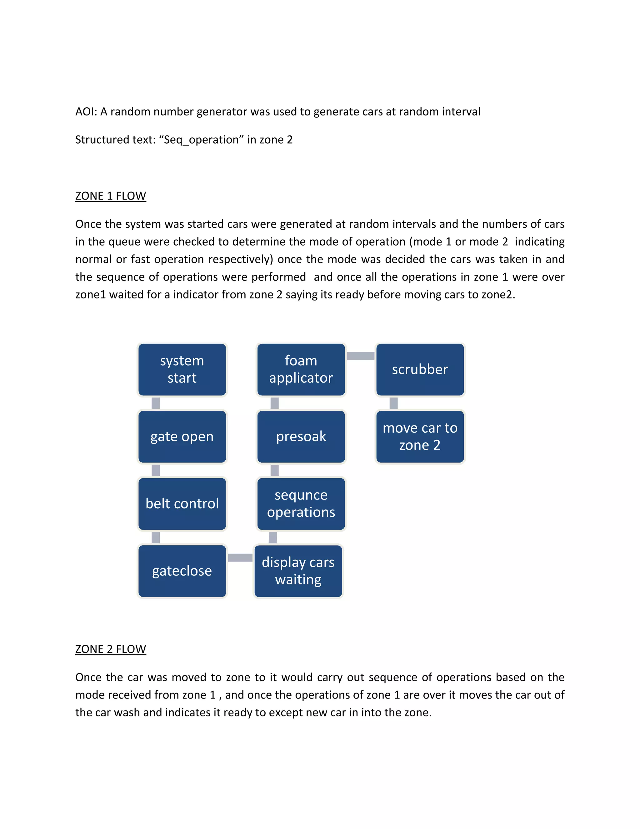
AOI: A randomnumber generator was used to generate cars at random interval
Structured text: “Seq_operation” in zone 2
ZONE 1 FLOW
Once the system was started cars were generated at random intervals and the numbers of cars
in the queue were checked to determine the mode of operation (mode 1 or mode 2 indicating
normal or fast operation respectively) once the mode was decided the cars was taken in and
the sequence of operations were performed and once all the operations in zone 1 were over
zone1 waited for a indicator from zone 2 saying its ready before moving cars to zone2.
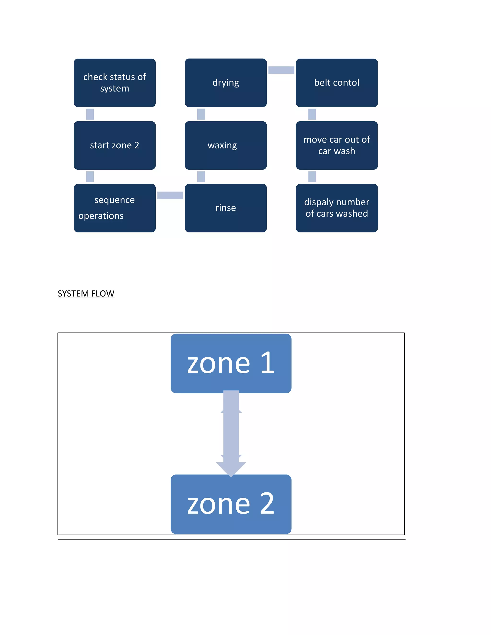
ZONE 2 FLOW
Once the car was moved to zone to it would carry out sequence of operations based on the
mode received from zone 1 , and once the operations of zone 1 are over it moves the car out of
the car wash and indicates it ready to except new car in into the zone.
system
start
gate open
belt control
gateclose
display cars
waiting
sequnce
operations
presoak
foam
applicator
scrubber
move car to
zone 2
3.
SYSTEM FLOW
check statusof
system
start zone 2
sequence
operations
rinse
waxing
drying belt contol
move car out of
car wash
dispaly number
of cars washed
zone 1
zone 2
4.
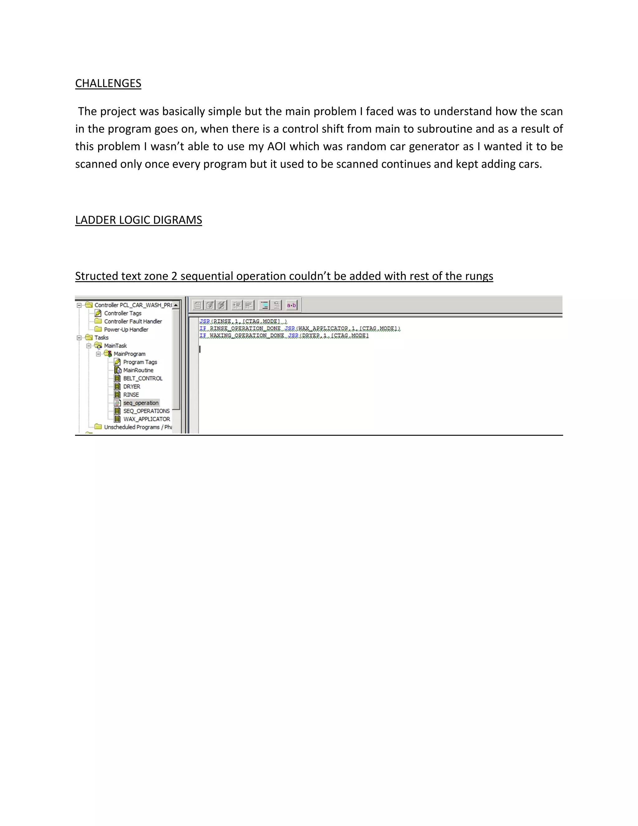
CHALLENGES
The project wasbasically simple but the main problem I faced was to understand how the scan
in the program goes on, when there is a control shift from main to subroutine and as a result of
this problem I wasn’t able to use my AOI which was random car generator as I wanted it to be
scanned only once every program but it used to be scanned continues and kept adding cars.
LADDER LOGIC DIGRAMS
Structed text zone 2 sequential operation couldn’t be added with rest of the rungs
5.
MainRoutine - LadderDiagram Page 1
PLC_CARWASH_PROJECT:MainTask:MainProgram 12/12/2015 10:32:41 PM
Total number of rungs in routine: 9 C:Userskxr3779DocumentsPLC_CARWASH_PROJECT.ACD
RSLogix 5000
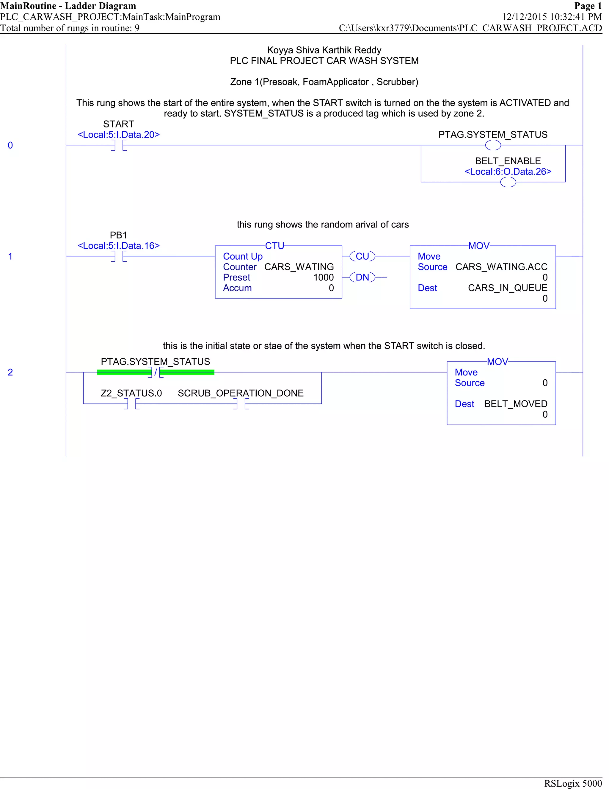
Koyya Shiva Karthik Reddy
PLC FINAL PROJECT CAR WASH SYSTEM
Zone 1(Presoak, FoamApplicator , Scrubber)
This rung shows the start of the entire system, when the START switch is turned on the the system is ACTIVATED and
ready to start. SYSTEM_STATUS is a produced tag which is used by zone 2.
0
START
<Local:5:I.Data.20> PTAG.SYSTEM_STATUS
BELT_ENABLE
<Local:6:O.Data.26>
Koyya Shiva Karthik Reddy
PLC FINAL PROJECT CAR WASH SYSTEM
Zone 1(Presoak, FoamApplicator , Scrubber)
This rung shows the start of the entire system, when the START switch is turned on the the system is ACTIVATED and
ready to start. SYSTEM_STATUS is a produced tag which is used by zone 2.
this rung shows the random arival of cars
1
PB1
<Local:5:I.Data.16>
CU
DN
Count Up
Counter CARS_WATING
Preset 1000
Accum 0
CTU
Move
Source CARS_WATING.ACC
0
Dest CARS_IN_QUEUE
0
MOV
this rung shows the random arival of cars
this is the initial state or stae of the system when the START switch is closed.
2 /
PTAG.SYSTEM_STATUS
Z2_STATUS.0 SCRUB_OPERATION_DONE
Move
Source 0
Dest BELT_MOVED
0
MOV
this is the initial state or stae of the system when the START switch is closed.
6.
MainRoutine - LadderDiagram Page 2
PLC_CARWASH_PROJECT:MainTask:MainProgram 12/12/2015 10:32:50 PM
Total number of rungs in routine: 9 C:Userskxr3779DocumentsPLC_CARWASH_PROJECT.ACD
RSLogix 5000
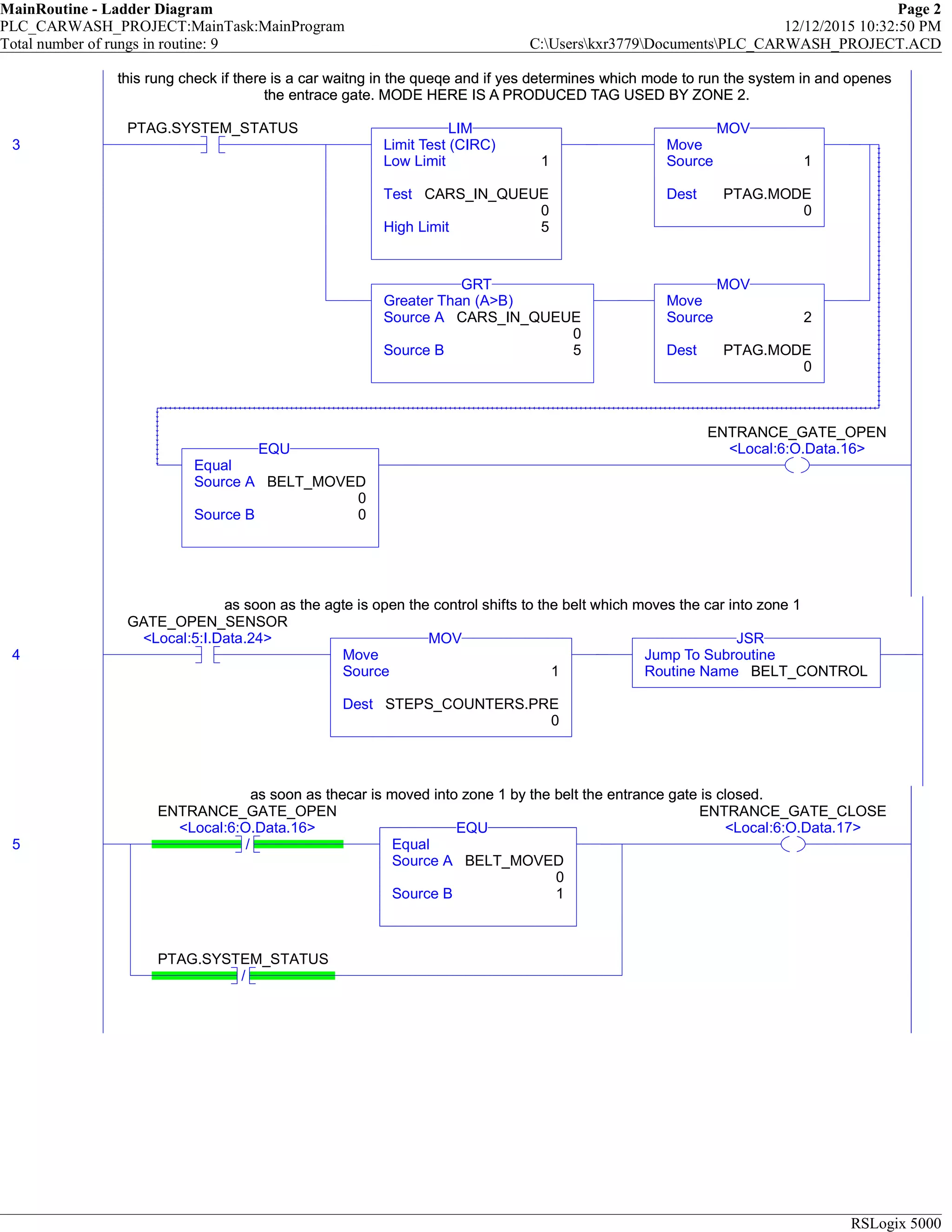
this rung check if there is a car waitng in the queqe and if yes determines which mode to run the system in and openes
the entrace gate. MODE HERE IS A PRODUCED TAG USED BY ZONE 2.
3
PTAG.SYSTEM_STATUS
Limit Test (CIRC)
Low Limit 1
Test CARS_IN_QUEUE
0
High Limit 5
LIM
Move
Source 1
Dest PTAG.MODE
0
MOV
Greater Than (A>B)
Source A CARS_IN_QUEUE
0
Source B 5
GRT
Move
Source 2
Dest PTAG.MODE
0
MOV
Equal
Source A BELT_MOVED
0
Source B 0
EQU
ENTRANCE_GATE_OPEN
<Local:6:O.Data.16>
this rung check if there is a car waitng in the queqe and if yes determines which mode to run the system in and openes
the entrace gate. MODE HERE IS A PRODUCED TAG USED BY ZONE 2.
as soon as the agte is open the control shifts to the belt which moves the car into zone 1
4
GATE_OPEN_SENSOR
<Local:5:I.Data.24>
Move
Source 1
Dest STEPS_COUNTERS.PRE
0
MOV
Jump To Subroutine
Routine Name BELT_CONTROL
JSR
as soon as the agte is open the control shifts to the belt which moves the car into zone 1
as soon as thecar is moved into zone 1 by the belt the entrance gate is closed.
5 /
ENTRANCE_GATE_OPEN
<Local:6:O.Data.16>
Equal
Source A BELT_MOVED
0
Source B 1
EQU
/
PTAG.SYSTEM_STATUS
ENTRANCE_GATE_CLOSE
<Local:6:O.Data.17>
as soon as thecar is moved into zone 1 by the belt the entrance gate is closed.
7.
MainRoutine - LadderDiagram Page 3
PLC_CARWASH_PROJECT:MainTask:MainProgram 12/12/2015 10:32:52 PM
Total number of rungs in routine: 9 C:Userskxr3779DocumentsPLC_CARWASH_PROJECT.ACD
RSLogix 5000
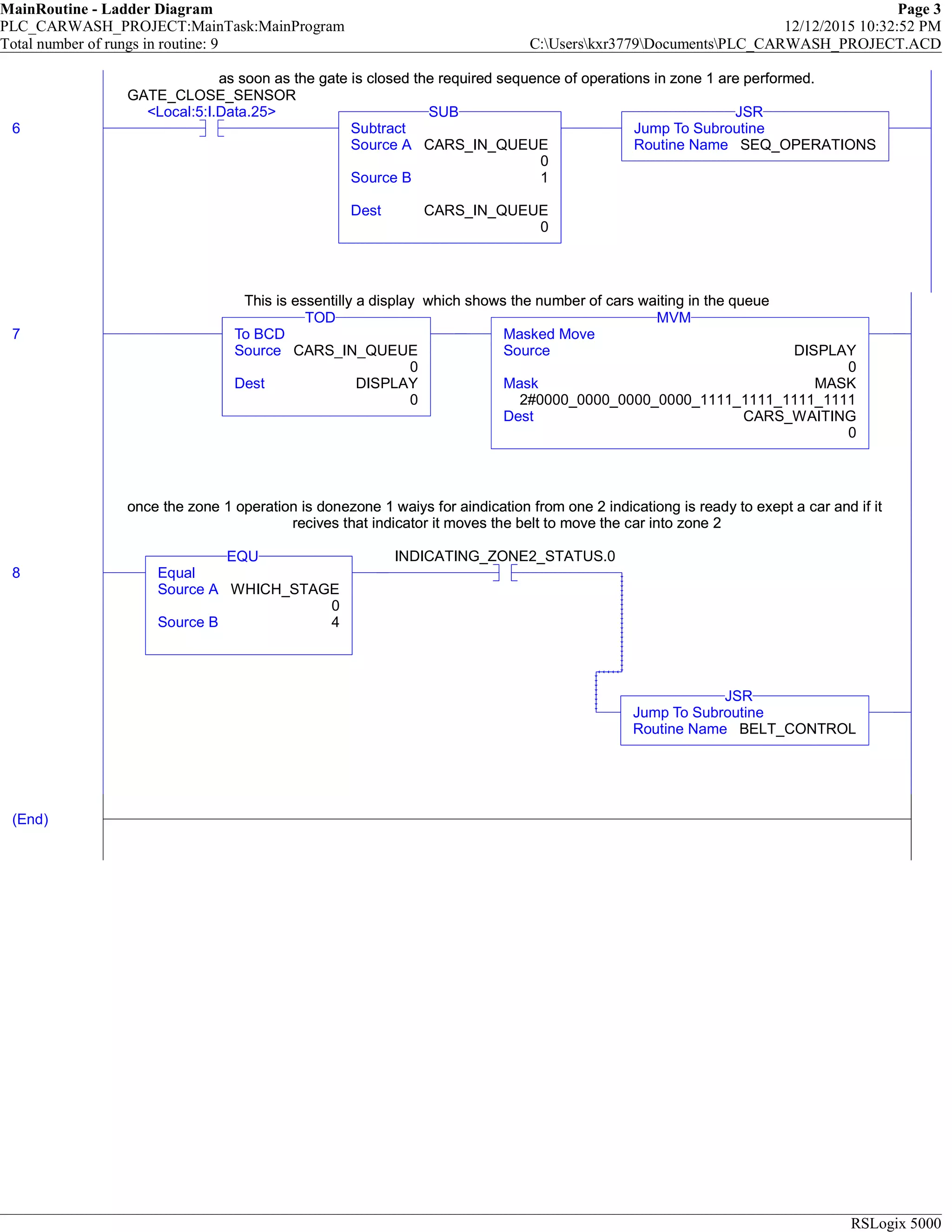
as soon as the gate is closed the required sequence of operations in zone 1 are performed.
6
GATE_CLOSE_SENSOR
<Local:5:I.Data.25>
Subtract
Source A CARS_IN_QUEUE
0
Source B 1
Dest CARS_IN_QUEUE
0
SUB
Jump To Subroutine
Routine Name SEQ_OPERATIONS
JSR
as soon as the gate is closed the required sequence of operations in zone 1 are performed.
This is essentilly a display which shows the number of cars waiting in the queue
7 To BCD
Source CARS_IN_QUEUE
0
Dest DISPLAY
0
TOD
Masked Move
Source DISPLAY
0
Mask MASK
2#0000_0000_0000_0000_1111_1111_1111_1111
Dest CARS_WAITING
0
MVM
This is essentilly a display which shows the number of cars waiting in the queue
once the zone 1 operation is donezone 1 waiys for aindication from one 2 indicationg is ready to exept a car and if it
recives that indicator it moves the belt to move the car into zone 2
8 Equal
Source A WHICH_STAGE
0
Source B 4
EQU INDICATING_ZONE2_STATUS.0
Jump To Subroutine
Routine Name BELT_CONTROL
JSR
once the zone 1 operation is donezone 1 waiys for aindication from one 2 indicationg is ready to exept a car and if it
recives that indicator it moves the belt to move the car into zone 2
(End)
8.
BELT_CONTROL - LadderDiagram Page 1
PLC_CARWASH_PROJECT:MainTask:MainProgram 12/12/2015 10:35:14 PM
Total number of rungs in routine: 7 C:Userskxr3779DocumentsPLC_CARWASH_PROJECT.ACD
RSLogix 5000
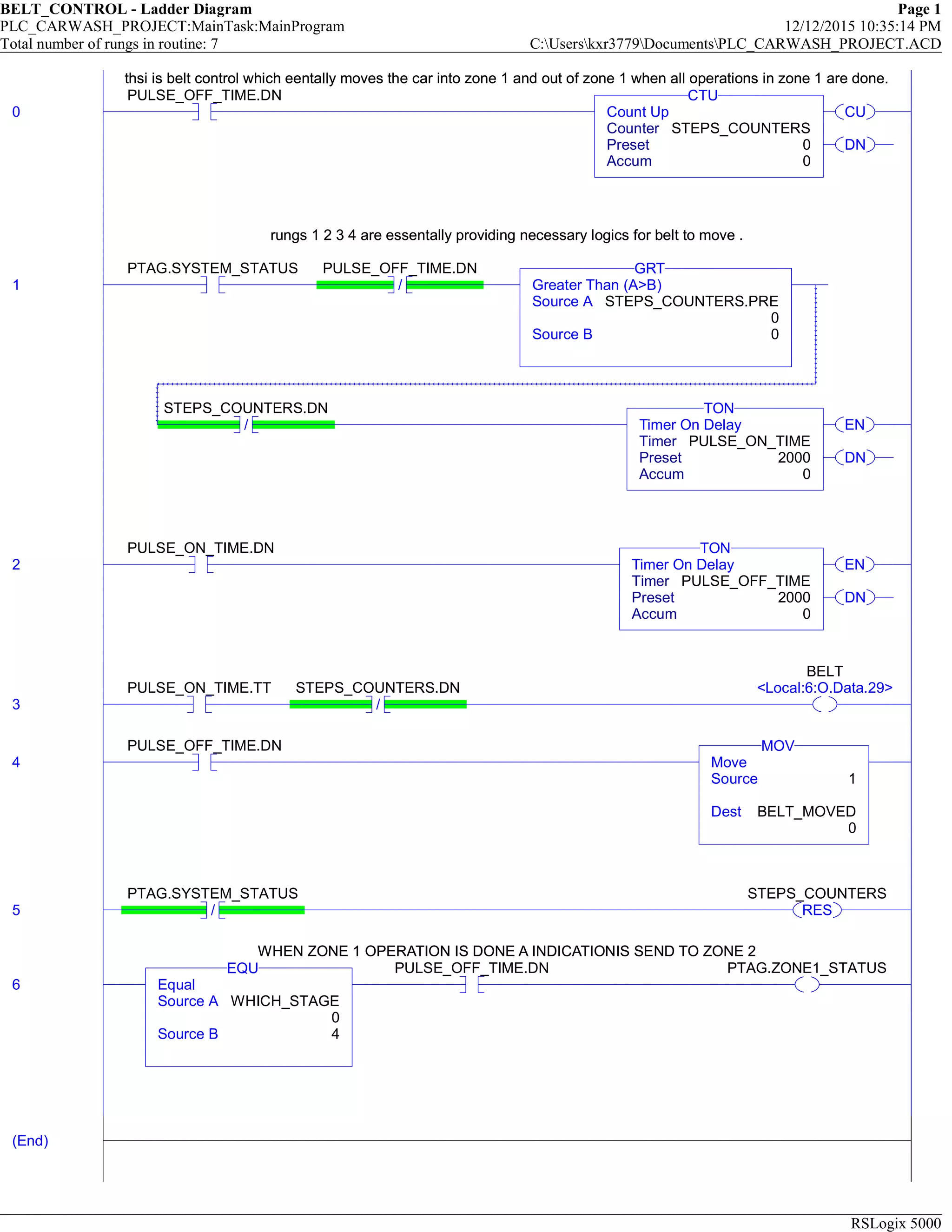
thsi is belt control which eentally moves the car into zone 1 and out of zone 1 when all operations in zone 1 are done.
0
PULSE_OFF_TIME.DN
CU
DN
Count Up
Counter STEPS_COUNTERS
Preset 0
Accum 0
CTU
thsi is belt control which eentally moves the car into zone 1 and out of zone 1 when all operations in zone 1 are done.
rungs 1 2 3 4 are essentally providing necessary logics for belt to move .
1
PTAG.SYSTEM_STATUS
/
PULSE_OFF_TIME.DN
Greater Than (A>B)
Source A STEPS_COUNTERS.PRE
0
Source B 0
GRT
/
STEPS_COUNTERS.DN
EN
DN
Timer On Delay
Timer PULSE_ON_TIME
Preset 2000
Accum 0
TON
rungs 1 2 3 4 are essentally providing necessary logics for belt to move .
2
PULSE_ON_TIME.DN
EN
DN
Timer On Delay
Timer PULSE_OFF_TIME
Preset 2000
Accum 0
TON
3
PULSE_ON_TIME.TT
/
STEPS_COUNTERS.DN
BELT
<Local:6:O.Data.29>
4
PULSE_OFF_TIME.DN
Move
Source 1
Dest BELT_MOVED
0
MOV
5 /
PTAG.SYSTEM_STATUS
RES
STEPS_COUNTERS
WHEN ZONE 1 OPERATION IS DONE A INDICATIONIS SEND TO ZONE 2
6 Equal
Source A WHICH_STAGE
0
Source B 4
EQU PULSE_OFF_TIME.DN PTAG.ZONE1_STATUS
WHEN ZONE 1 OPERATION IS DONE A INDICATIONIS SEND TO ZONE 2
(End)
9.
SEQ_OPERATIONS - LadderDiagram Page 1
PLC_CARWASH_PROJECT:MainTask:MainProgram 12/12/2015 10:36:06 PM
Total number of rungs in routine: 4 C:Userskxr3779DocumentsPLC_CARWASH_PROJECT.ACD
RSLogix 5000
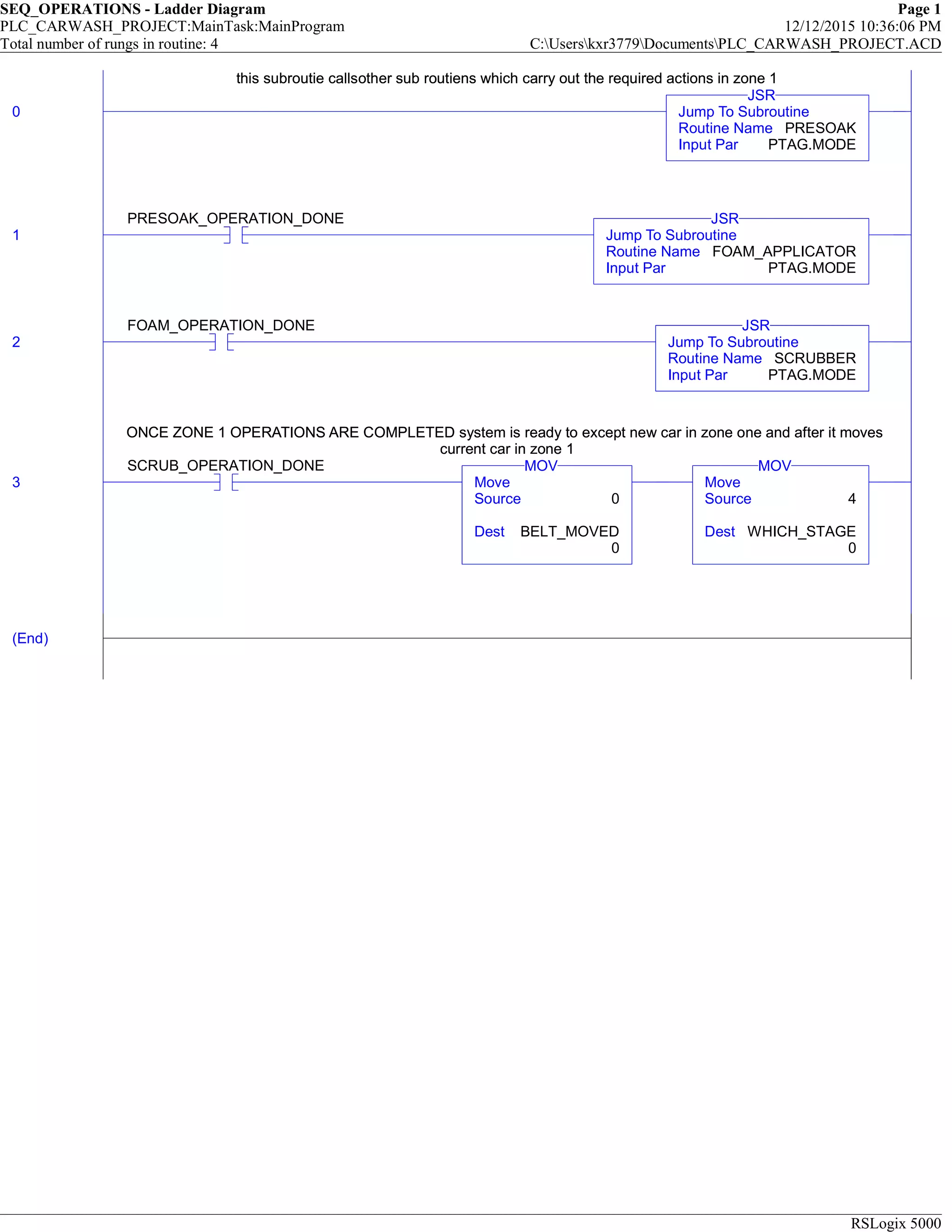
this subroutie callsother sub routiens which carry out the required actions in zone 1
0 Jump To Subroutine
Routine Name PRESOAK
Input Par PTAG.MODE
JSR
this subroutie callsother sub routiens which carry out the required actions in zone 1
1
PRESOAK_OPERATION_DONE
Jump To Subroutine
Routine Name FOAM_APPLICATOR
Input Par PTAG.MODE
JSR
2
FOAM_OPERATION_DONE
Jump To Subroutine
Routine Name SCRUBBER
Input Par PTAG.MODE
JSR
ONCE ZONE 1 OPERATIONS ARE COMPLETED system is ready to except new car in zone one and after it moves
current car in zone 1
3
SCRUB_OPERATION_DONE
Move
Source 0
Dest BELT_MOVED
0
MOV
Move
Source 4
Dest WHICH_STAGE
0
MOV
ONCE ZONE 1 OPERATIONS ARE COMPLETED system is ready to except new car in zone one and after it moves
current car in zone 1
(End)
10.
PRESOAK - LadderDiagram Page 1
PLC_CARWASH_PROJECT:MainTask:MainProgram 12/12/2015 10:44:17 PM
Total number of rungs in routine: 9 C:Userskxr3779DocumentsPLC_CARWASH_PROJECT.ACD
RSLogix 5000
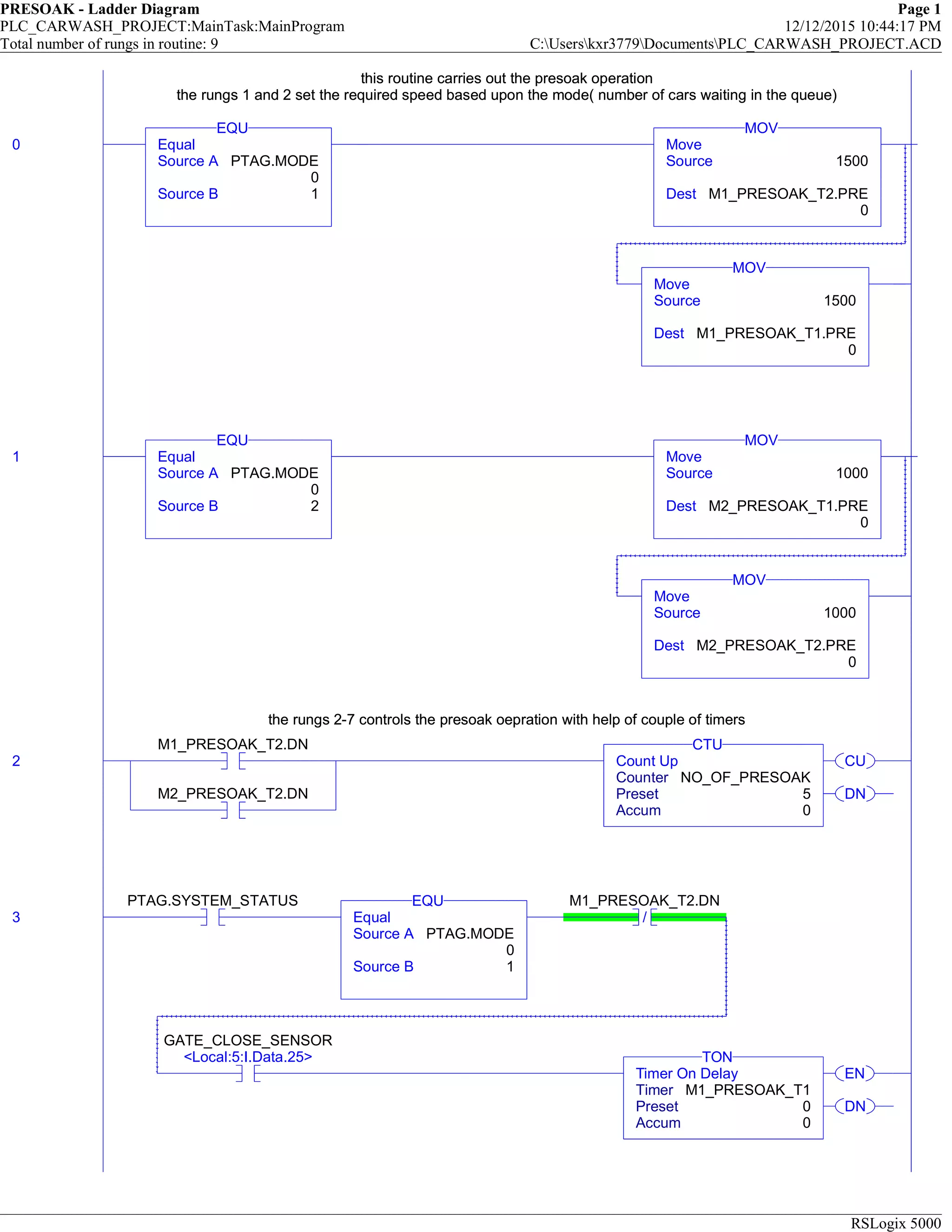
this routine carries out the presoak operation
the rungs 1 and 2 set the required speed based upon the mode( number of cars waiting in the queue)
0 Equal
Source A PTAG.MODE
0
Source B 1
EQU
Move
Source 1500
Dest M1_PRESOAK_T2.PRE
0
MOV
Move
Source 1500
Dest M1_PRESOAK_T1.PRE
0
MOV
this routine carries out the presoak operation
the rungs 1 and 2 set the required speed based upon the mode( number of cars waiting in the queue)
1 Equal
Source A PTAG.MODE
0
Source B 2
EQU
Move
Source 1000
Dest M2_PRESOAK_T1.PRE
0
MOV
Move
Source 1000
Dest M2_PRESOAK_T2.PRE
0
MOV
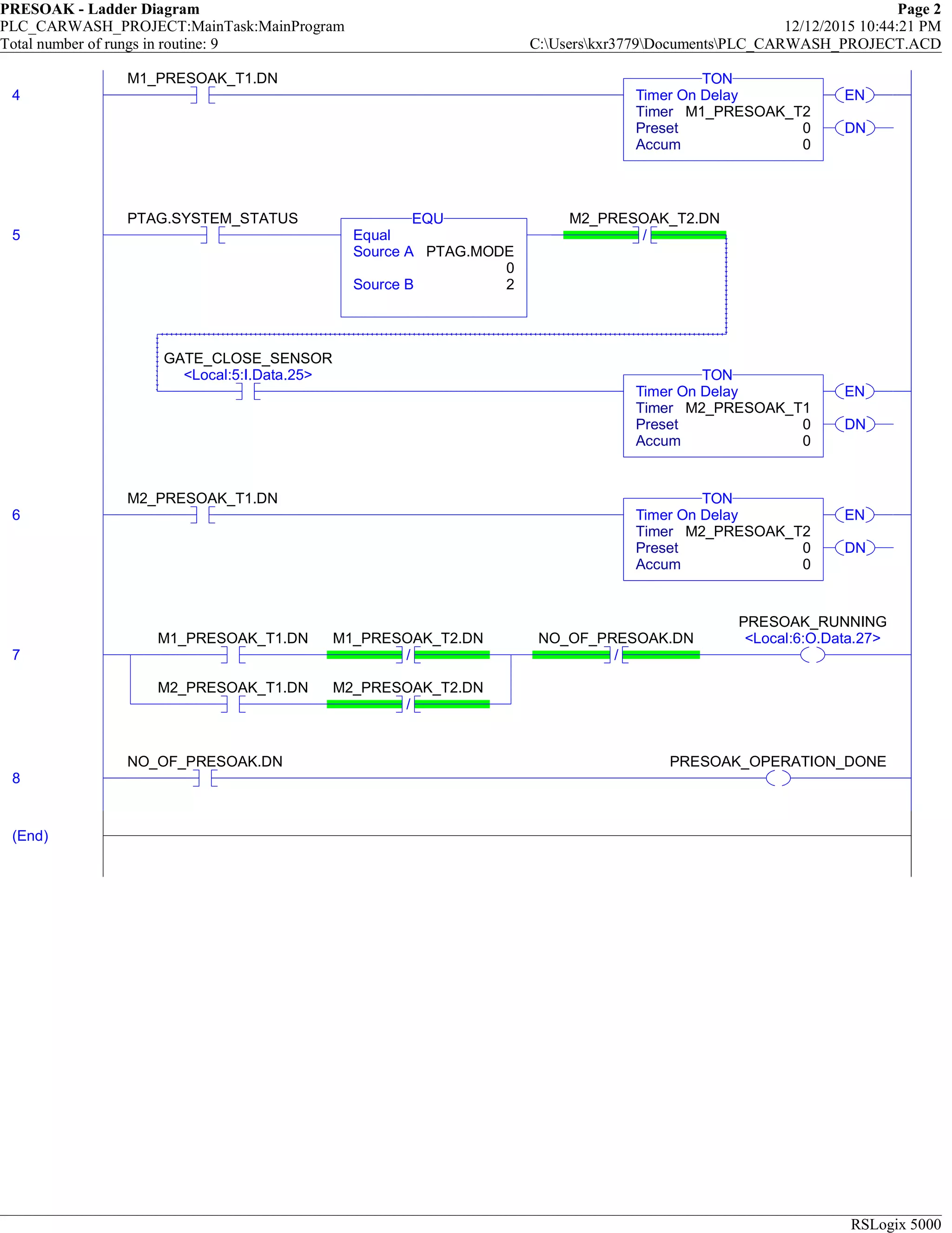
the rungs 2-7 controls the presoak oepration with help of couple of timers
2
M1_PRESOAK_T2.DN
M2_PRESOAK_T2.DN
CU
DN
Count Up
Counter NO_OF_PRESOAK
Preset 5
Accum 0
CTU
the rungs 2-7 controls the presoak oepration with help of couple of timers
3
PTAG.SYSTEM_STATUS
Equal
Source A PTAG.MODE
0
Source B 1
EQU
/
M1_PRESOAK_T2.DN
GATE_CLOSE_SENSOR
<Local:5:I.Data.25>
EN
DN
Timer On Delay
Timer M1_PRESOAK_T1
Preset 0
Accum 0
TON
11.
PRESOAK - LadderDiagram Page 2
PLC_CARWASH_PROJECT:MainTask:MainProgram 12/12/2015 10:44:21 PM
Total number of rungs in routine: 9 C:Userskxr3779DocumentsPLC_CARWASH_PROJECT.ACD
RSLogix 5000
4
M1_PRESOAK_T1.DN
EN
DN
Timer On Delay
Timer M1_PRESOAK_T2
Preset 0
Accum 0
TON
5
PTAG.SYSTEM_STATUS
Equal
Source A PTAG.MODE
0
Source B 2
EQU
/
M2_PRESOAK_T2.DN
GATE_CLOSE_SENSOR
<Local:5:I.Data.25>
EN
DN
Timer On Delay
Timer M2_PRESOAK_T1
Preset 0
Accum 0
TON
6
M2_PRESOAK_T1.DN
EN
DN
Timer On Delay
Timer M2_PRESOAK_T2
Preset 0
Accum 0
TON
7
M1_PRESOAK_T1.DN
/
M1_PRESOAK_T2.DN
M2_PRESOAK_T1.DN
/
M2_PRESOAK_T2.DN
/
NO_OF_PRESOAK.DN
PRESOAK_RUNNING
<Local:6:O.Data.27>
8
NO_OF_PRESOAK.DN PRESOAK_OPERATION_DONE
(End)
12.
FOAM_APPLICATOR - LadderDiagram Page 1
PLC_CARWASH_PROJECT:MainTask:MainProgram 12/12/2015 10:44:51 PM
Total number of rungs in routine: 5 C:Userskxr3779DocumentsPLC_CARWASH_PROJECT.ACD
RSLogix 5000
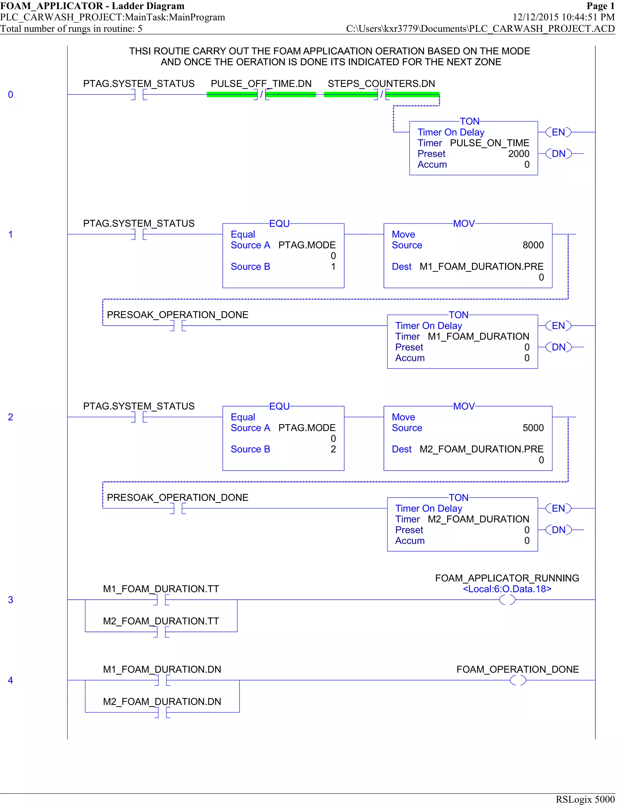
THSI ROUTIE CARRY OUT THE FOAM APPLICAATION OERATION BASED ON THE MODE
AND ONCE THE OERATION IS DONE ITS INDICATED FOR THE NEXT ZONE
0
PTAG.SYSTEM_STATUS
/
PULSE_OFF_TIME.DN
/
STEPS_COUNTERS.DN
EN
DN
Timer On Delay
Timer PULSE_ON_TIME
Preset 2000
Accum 0
TON
THSI ROUTIE CARRY OUT THE FOAM APPLICAATION OERATION BASED ON THE MODE
AND ONCE THE OERATION IS DONE ITS INDICATED FOR THE NEXT ZONE
1
PTAG.SYSTEM_STATUS
Equal
Source A PTAG.MODE
0
Source B 1
EQU
Move
Source 8000
Dest M1_FOAM_DURATION.PRE
0
MOV
PRESOAK_OPERATION_DONE
EN
DN
Timer On Delay
Timer M1_FOAM_DURATION
Preset 0
Accum 0
TON
2
PTAG.SYSTEM_STATUS
Equal
Source A PTAG.MODE
0
Source B 2
EQU
Move
Source 5000
Dest M2_FOAM_DURATION.PRE
0
MOV
PRESOAK_OPERATION_DONE
EN
DN
Timer On Delay
Timer M2_FOAM_DURATION
Preset 0
Accum 0
TON
3
M1_FOAM_DURATION.TT
M2_FOAM_DURATION.TT
FOAM_APPLICATOR_RUNNING
<Local:6:O.Data.18>
4
M1_FOAM_DURATION.DN
M2_FOAM_DURATION.DN
FOAM_OPERATION_DONE
13.
FOAM_APPLICATOR - LadderDiagram Page 2
PLC_CARWASH_PROJECT:MainTask:MainProgram 12/12/2015 10:44:54 PM
Total number of rungs in routine: 5 C:Userskxr3779DocumentsPLC_CARWASH_PROJECT.ACD
RSLogix 5000
(End)
14.
SCRUBBER - LadderDiagram Page 1
PLC_CARWASH_PROJECT:MainTask:MainProgram 12/12/2015 10:45:30 PM
Total number of rungs in routine: 10 C:Userskxr3779DocumentsPLC_CARWASH_PROJECT.ACD
RSLogix 5000
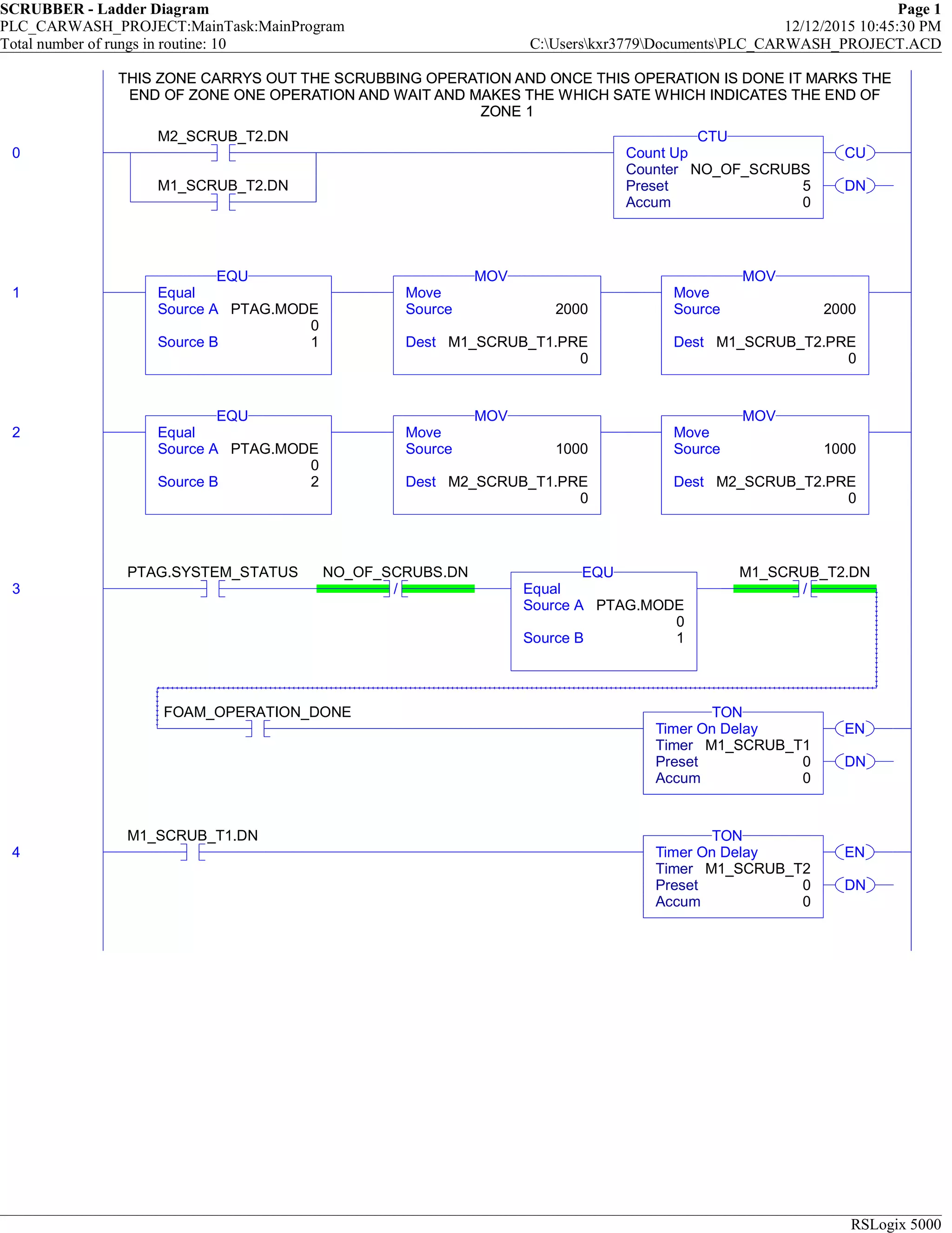
THIS ZONE CARRYS OUT THE SCRUBBING OPERATION AND ONCE THIS OPERATION IS DONE IT MARKS THE
END OF ZONE ONE OPERATION AND WAIT AND MAKES THE WHICH SATE WHICH INDICATES THE END OF
ZONE 1
0
M2_SCRUB_T2.DN
M1_SCRUB_T2.DN
CU
DN
Count Up
Counter NO_OF_SCRUBS
Preset 5
Accum 0
CTU
THIS ZONE CARRYS OUT THE SCRUBBING OPERATION AND ONCE THIS OPERATION IS DONE IT MARKS THE
END OF ZONE ONE OPERATION AND WAIT AND MAKES THE WHICH SATE WHICH INDICATES THE END OF
ZONE 1
1 Equal
Source A PTAG.MODE
0
Source B 1
EQU
Move
Source 2000
Dest M1_SCRUB_T1.PRE
0
MOV
Move
Source 2000
Dest M1_SCRUB_T2.PRE
0
MOV
2 Equal
Source A PTAG.MODE
0
Source B 2
EQU
Move
Source 1000
Dest M2_SCRUB_T1.PRE
0
MOV
Move
Source 1000
Dest M2_SCRUB_T2.PRE
0
MOV
3
PTAG.SYSTEM_STATUS
/
NO_OF_SCRUBS.DN
Equal
Source A PTAG.MODE
0
Source B 1
EQU
/
M1_SCRUB_T2.DN
FOAM_OPERATION_DONE
EN
DN
Timer On Delay
Timer M1_SCRUB_T1
Preset 0
Accum 0
TON
4
M1_SCRUB_T1.DN
EN
DN
Timer On Delay
Timer M1_SCRUB_T2
Preset 0
Accum 0
TON
15.
SCRUBBER - LadderDiagram Page 2
PLC_CARWASH_PROJECT:MainTask:MainProgram 12/12/2015 10:45:34 PM
Total number of rungs in routine: 10 C:Userskxr3779DocumentsPLC_CARWASH_PROJECT.ACD
RSLogix 5000
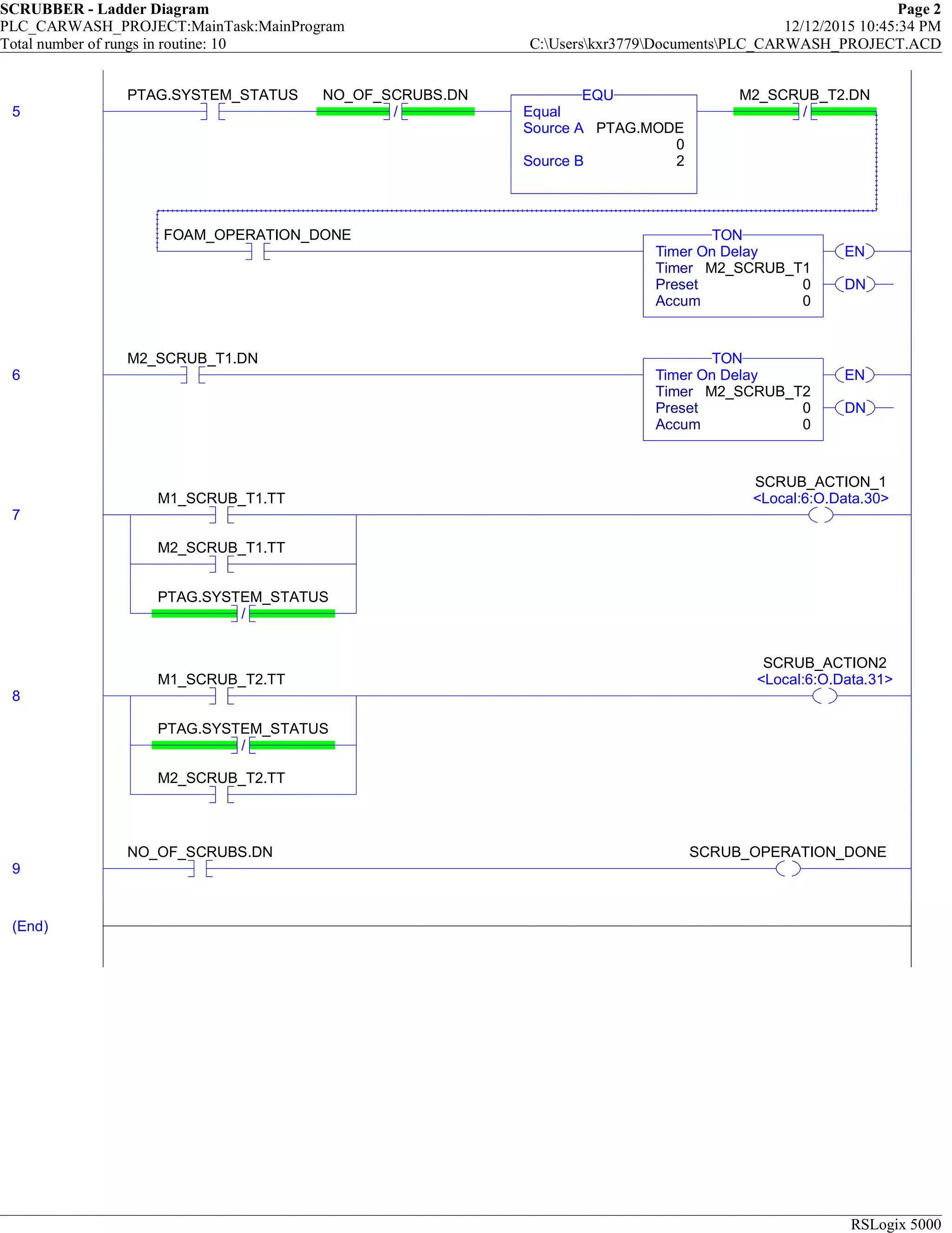
5
PTAG.SYSTEM_STATUS
/
NO_OF_SCRUBS.DN
Equal
Source A PTAG.MODE
0
Source B 2
EQU
/
M2_SCRUB_T2.DN
FOAM_OPERATION_DONE
EN
DN
Timer On Delay
Timer M2_SCRUB_T1
Preset 0
Accum 0
TON
6
M2_SCRUB_T1.DN
EN
DN
Timer On Delay
Timer M2_SCRUB_T2
Preset 0
Accum 0
TON
7
M1_SCRUB_T1.TT
M2_SCRUB_T1.TT
/
PTAG.SYSTEM_STATUS
SCRUB_ACTION_1
<Local:6:O.Data.30>
8
M1_SCRUB_T2.TT
/
PTAG.SYSTEM_STATUS
M2_SCRUB_T2.TT
SCRUB_ACTION2
<Local:6:O.Data.31>
9
NO_OF_SCRUBS.DN SCRUB_OPERATION_DONE
(End)
16.
MainRoutine - LadderDiagram Page 1
PCL_CAR_WASH_PROJECT_ZONE2:MainTask:MainProgram 12/12/2015 10:50:24 PM
Total number of rungs in routine: 8 C:Userskxr3779DocumentsPCL_CAR_WASH_PROJECT_ZONE2.ACD
RSLogix 5000
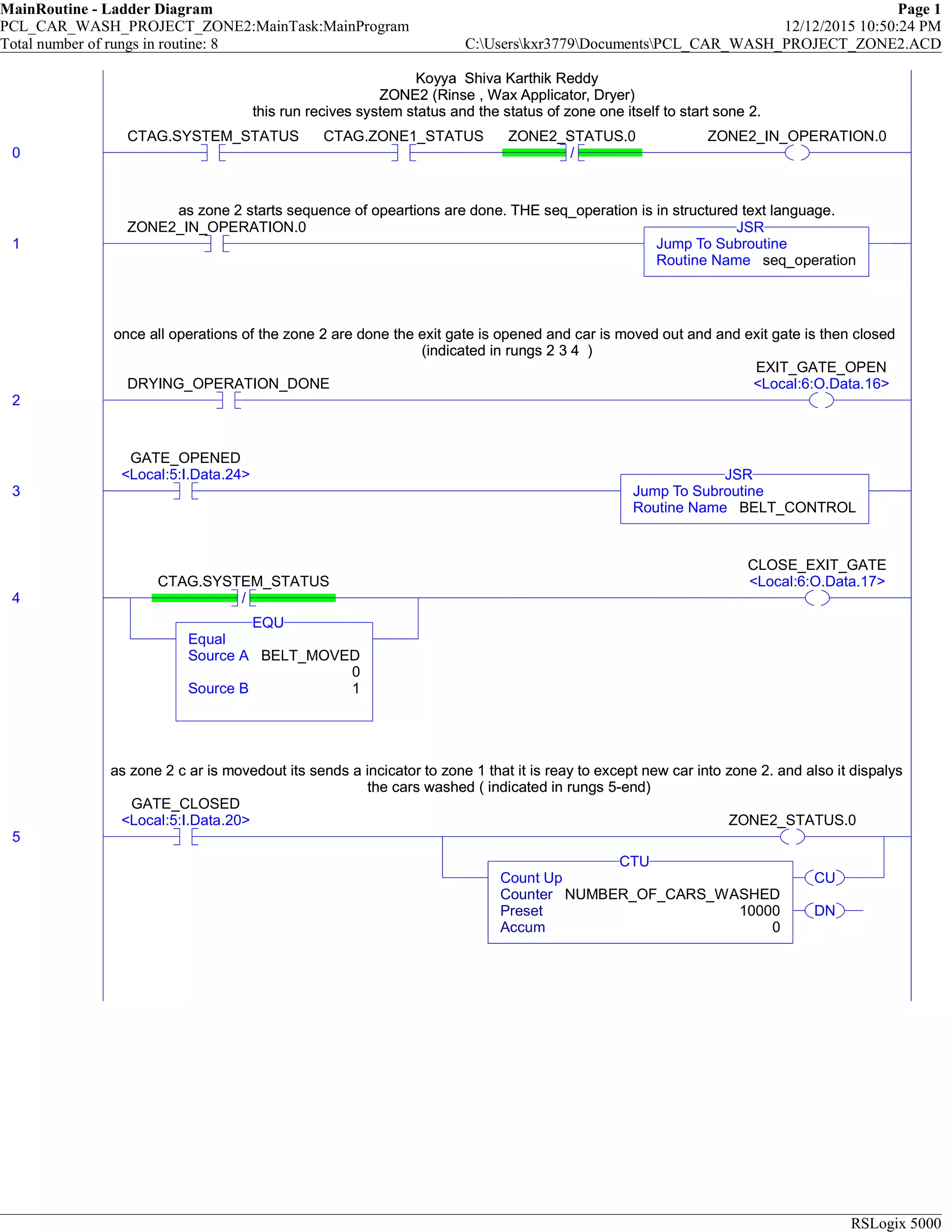
Koyya Shiva Karthik Reddy
ZONE2 (Rinse , Wax Applicator, Dryer)
this run recives system status and the status of zone one itself to start sone 2.
0
CTAG.SYSTEM_STATUS CTAG.ZONE1_STATUS
/
ZONE2_STATUS.0 ZONE2_IN_OPERATION.0
Koyya Shiva Karthik Reddy
ZONE2 (Rinse , Wax Applicator, Dryer)
this run recives system status and the status of zone one itself to start sone 2.
as zone 2 starts sequence of opeartions are done. THE seq_operation is in structured text language.
1
ZONE2_IN_OPERATION.0
Jump To Subroutine
Routine Name seq_operation
JSR
as zone 2 starts sequence of opeartions are done. THE seq_operation is in structured text language.
once all operations of the zone 2 are done the exit gate is opened and car is moved out and and exit gate is then closed
(indicated in rungs 2 3 4 )
2
DRYING_OPERATION_DONE
EXIT_GATE_OPEN
<Local:6:O.Data.16>
once all operations of the zone 2 are done the exit gate is opened and car is moved out and and exit gate is then closed
(indicated in rungs 2 3 4 )
3
GATE_OPENED
<Local:5:I.Data.24>
Jump To Subroutine
Routine Name BELT_CONTROL
JSR
4 /
CTAG.SYSTEM_STATUS
Equal
Source A BELT_MOVED
0
Source B 1
EQU
CLOSE_EXIT_GATE
<Local:6:O.Data.17>
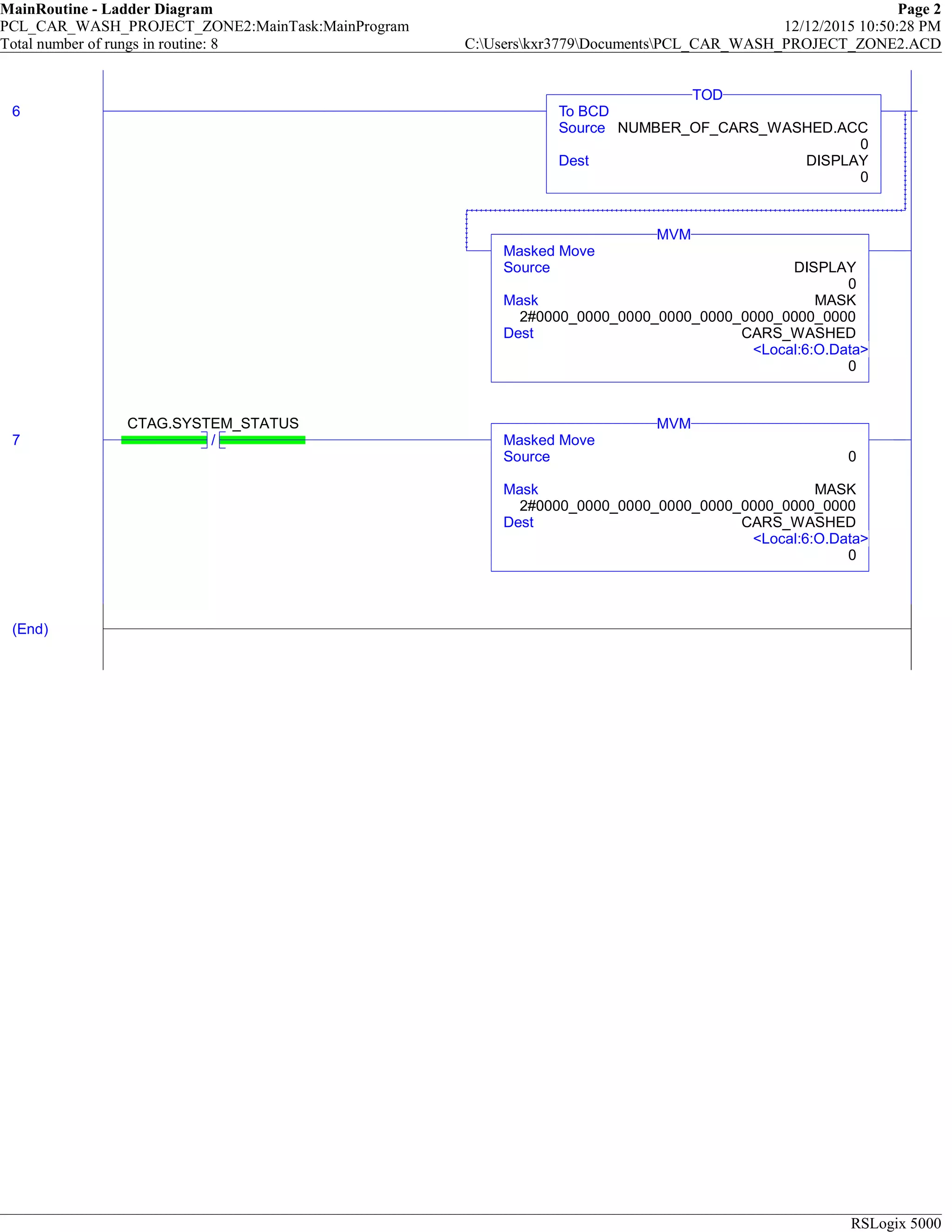
as zone 2 c ar is movedout its sends a incicator to zone 1 that it is reay to except new car into zone 2. and also it dispalys
the cars washed ( indicated in rungs 5-end)
5
GATE_CLOSED
<Local:5:I.Data.20> ZONE2_STATUS.0
CU
DN
Count Up
Counter NUMBER_OF_CARS_WASHED
Preset 10000
Accum 0
CTU
as zone 2 c ar is movedout its sends a incicator to zone 1 that it is reay to except new car into zone 2. and also it dispalys
the cars washed ( indicated in rungs 5-end)
17.
MainRoutine - LadderDiagram Page 2
PCL_CAR_WASH_PROJECT_ZONE2:MainTask:MainProgram 12/12/2015 10:50:28 PM
Total number of rungs in routine: 8 C:Userskxr3779DocumentsPCL_CAR_WASH_PROJECT_ZONE2.ACD
RSLogix 5000
6 To BCD
Source NUMBER_OF_CARS_WASHED.ACC
0
Dest DISPLAY
0
TOD
Masked Move
Source DISPLAY
0
Mask MASK
2#0000_0000_0000_0000_0000_0000_0000_0000
Dest CARS_WASHED
<Local:6:O.Data>
0
MVM
7 /
CTAG.SYSTEM_STATUS
Masked Move
Source 0
Mask MASK
2#0000_0000_0000_0000_0000_0000_0000_0000
Dest CARS_WASHED
<Local:6:O.Data>
0
MVM
(End)
18.
BELT_CONTROL - LadderDiagram Page 1
PCL_CAR_WASH_PROJECT_ZONE2:MainTask:MainProgram 12/12/2015 10:50:49 PM
Total number of rungs in routine: 5 C:Userskxr3779DocumentsPCL_CAR_WASH_PROJECT_ZONE2.ACD
RSLogix 5000
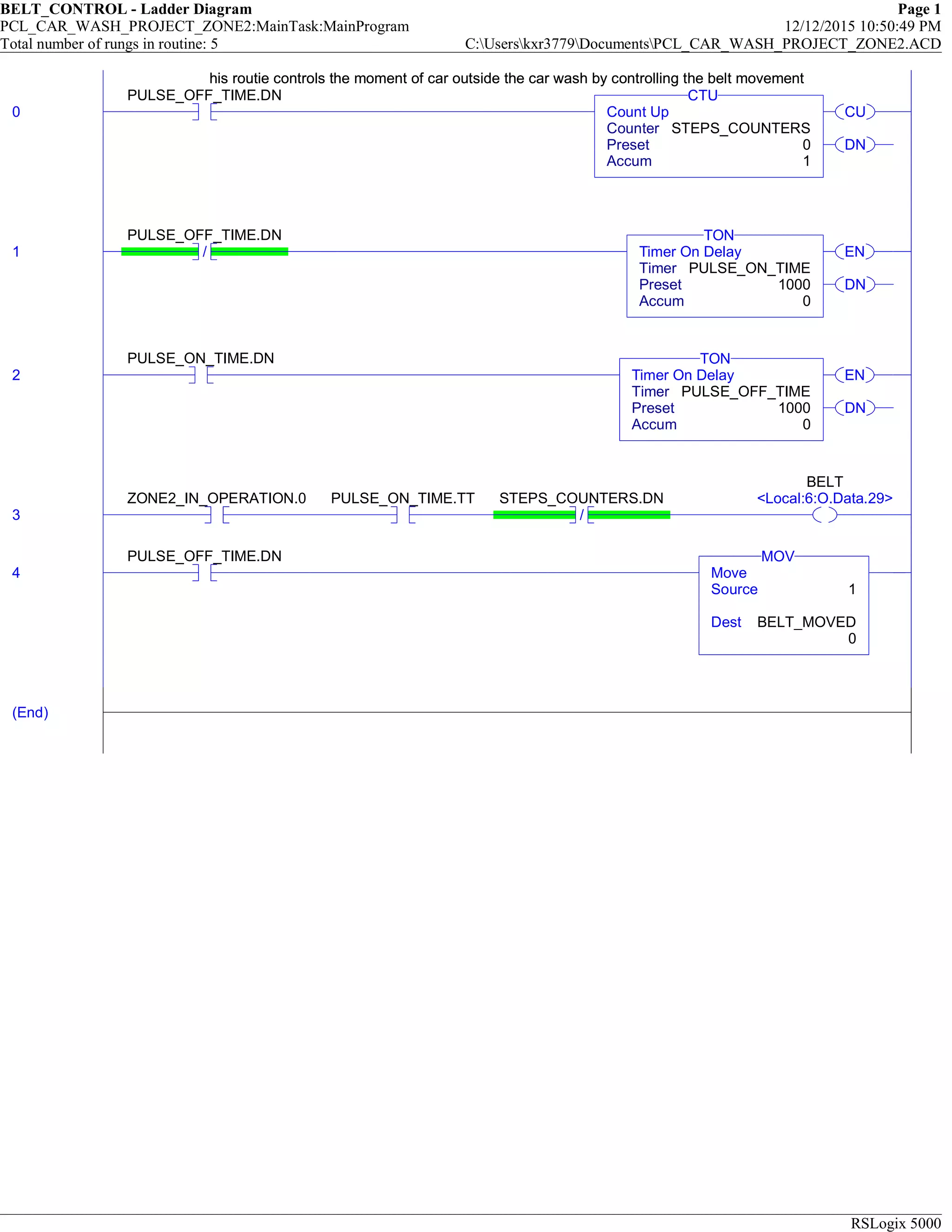
his routie controls the moment of car outside the car wash by controlling the belt movement
0
PULSE_OFF_TIME.DN
CU
DN
Count Up
Counter STEPS_COUNTERS
Preset 0
Accum 1
CTU
his routie controls the moment of car outside the car wash by controlling the belt movement
1 /
PULSE_OFF_TIME.DN
EN
DN
Timer On Delay
Timer PULSE_ON_TIME
Preset 1000
Accum 0
TON
2
PULSE_ON_TIME.DN
EN
DN
Timer On Delay
Timer PULSE_OFF_TIME
Preset 1000
Accum 0
TON
3
ZONE2_IN_OPERATION.0 PULSE_ON_TIME.TT
/
STEPS_COUNTERS.DN
BELT
<Local:6:O.Data.29>
4
PULSE_OFF_TIME.DN
Move
Source 1
Dest BELT_MOVED
0
MOV
(End)
19.
SEQ_OPERATIONS - LadderDiagram Page 1
PCL_CAR_WASH_PROJECT_ZONE2:MainTask:MainProgram 12/12/2015 10:51:30 PM
Total number of rungs in routine: 3 C:Userskxr3779DocumentsPCL_CAR_WASH_PROJECT_ZONE2.ACD
RSLogix 5000
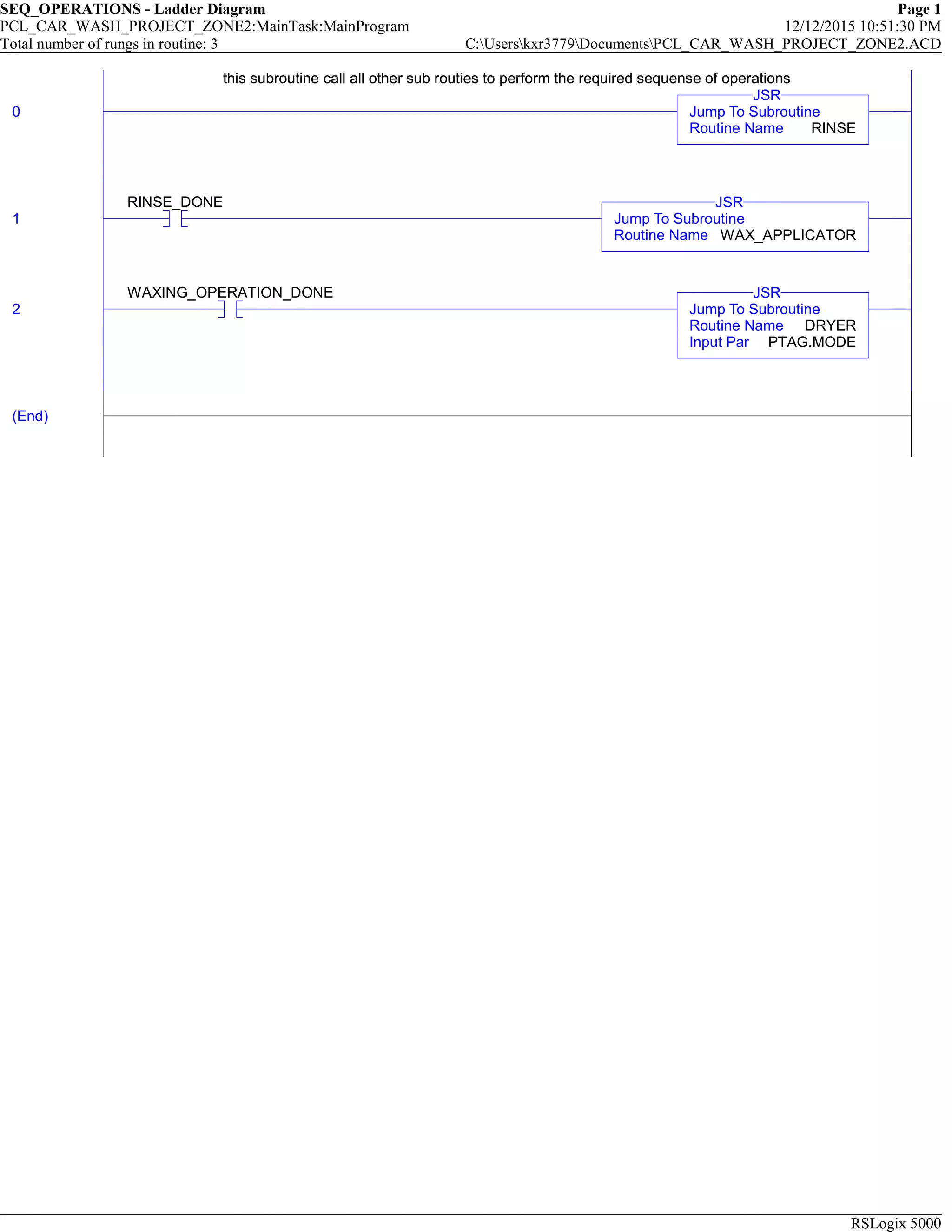
this subroutine call all other sub routies to perform the required sequense of operations
0 Jump To Subroutine
Routine Name RINSE
JSR
this subroutine call all other sub routies to perform the required sequense of operations
1
RINSE_DONE
Jump To Subroutine
Routine Name WAX_APPLICATOR
JSR
2
WAXING_OPERATION_DONE
Jump To Subroutine
Routine Name DRYER
Input Par PTAG.MODE
JSR
(End)
20.
RINSE - LadderDiagram Page 1
PCL_CAR_WASH_PROJECT_ZONE2:MainTask:MainProgram 12/12/2015 10:55:13 PM
Total number of rungs in routine: 10 C:Userskxr3779DocumentsPCL_CAR_WASH_PROJECT_ZONE2.ACD
RSLogix 5000
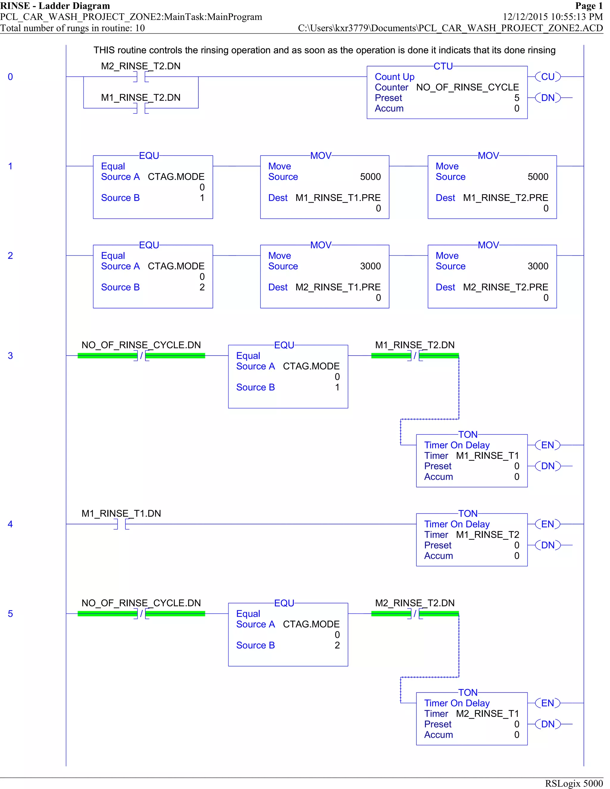
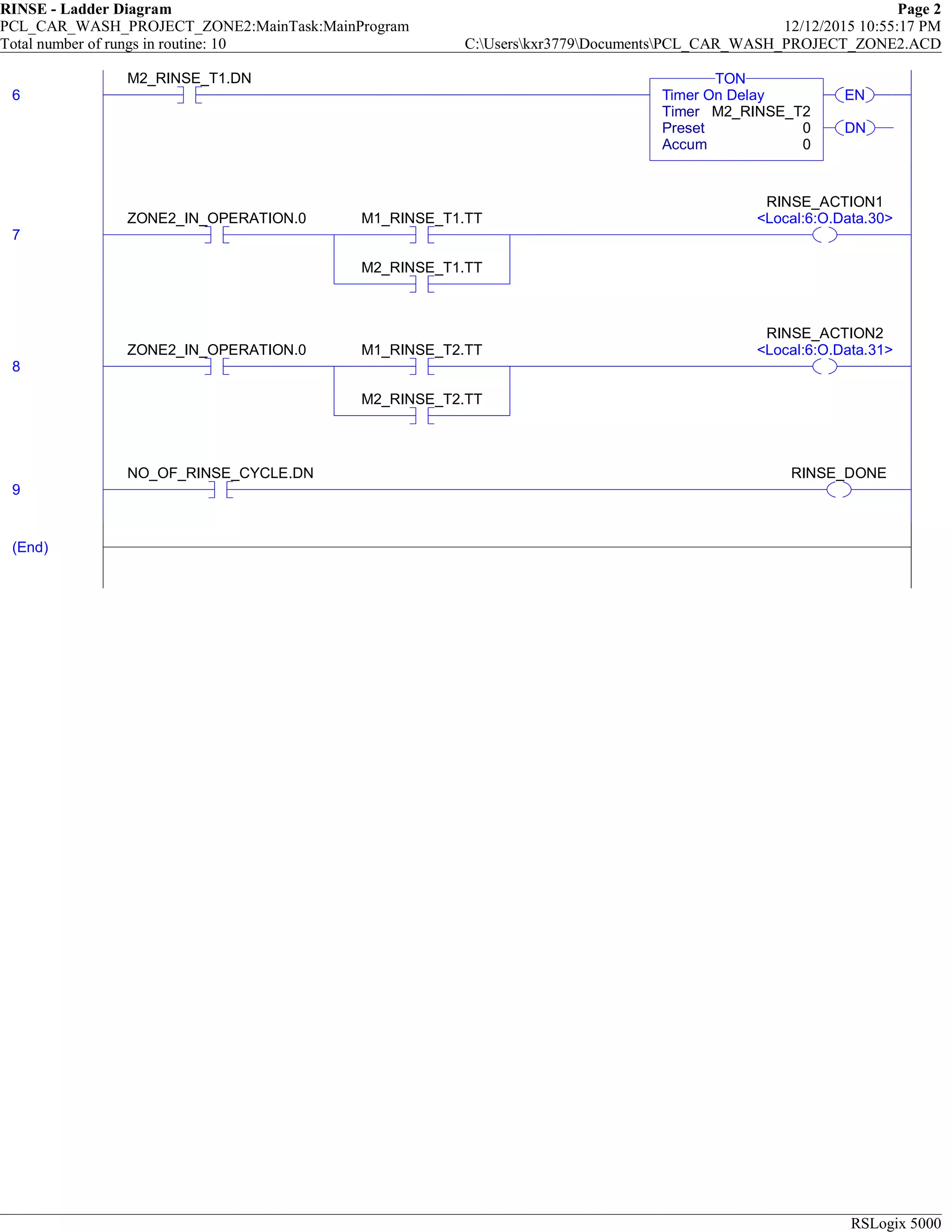
THIS routine controls the rinsing operation and as soon as the operation is done it indicats that its done rinsing
0
M2_RINSE_T2.DN
M1_RINSE_T2.DN
CU
DN
Count Up
Counter NO_OF_RINSE_CYCLE
Preset 5
Accum 0
CTU
THIS routine controls the rinsing operation and as soon as the operation is done it indicats that its done rinsing
1 Equal
Source A CTAG.MODE
0
Source B 1
EQU
Move
Source 5000
Dest M1_RINSE_T1.PRE
0
MOV
Move
Source 5000
Dest M1_RINSE_T2.PRE
0
MOV
2 Equal
Source A CTAG.MODE
0
Source B 2
EQU
Move
Source 3000
Dest M2_RINSE_T1.PRE
0
MOV
Move
Source 3000
Dest M2_RINSE_T2.PRE
0
MOV
3 /
NO_OF_RINSE_CYCLE.DN
Equal
Source A CTAG.MODE
0
Source B 1
EQU
/
M1_RINSE_T2.DN
EN
DN
Timer On Delay
Timer M1_RINSE_T1
Preset 0
Accum 0
TON
4
M1_RINSE_T1.DN
EN
DN
Timer On Delay
Timer M1_RINSE_T2
Preset 0
Accum 0
TON
5 /
NO_OF_RINSE_CYCLE.DN
Equal
Source A CTAG.MODE
0
Source B 2
EQU
/
M2_RINSE_T2.DN
EN
DN
Timer On Delay
Timer M2_RINSE_T1
Preset 0
Accum 0
TON
21.
RINSE - LadderDiagram Page 2
PCL_CAR_WASH_PROJECT_ZONE2:MainTask:MainProgram 12/12/2015 10:55:17 PM
Total number of rungs in routine: 10 C:Userskxr3779DocumentsPCL_CAR_WASH_PROJECT_ZONE2.ACD
RSLogix 5000
6
M2_RINSE_T1.DN
EN
DN
Timer On Delay
Timer M2_RINSE_T2
Preset 0
Accum 0
TON
7
ZONE2_IN_OPERATION.0 M1_RINSE_T1.TT
M2_RINSE_T1.TT
RINSE_ACTION1
<Local:6:O.Data.30>
8
ZONE2_IN_OPERATION.0 M1_RINSE_T2.TT
M2_RINSE_T2.TT
RINSE_ACTION2
<Local:6:O.Data.31>
9
NO_OF_RINSE_CYCLE.DN RINSE_DONE
(End)
22.
WAX_APPLICATOR - LadderDiagram Page 1
PCL_CAR_WASH_PROJECT_ZONE2:MainTask:MainProgram 12/12/2015 10:55:48 PM
Total number of rungs in routine: 9 C:Userskxr3779DocumentsPCL_CAR_WASH_PROJECT_ZONE2.ACD
RSLogix 5000
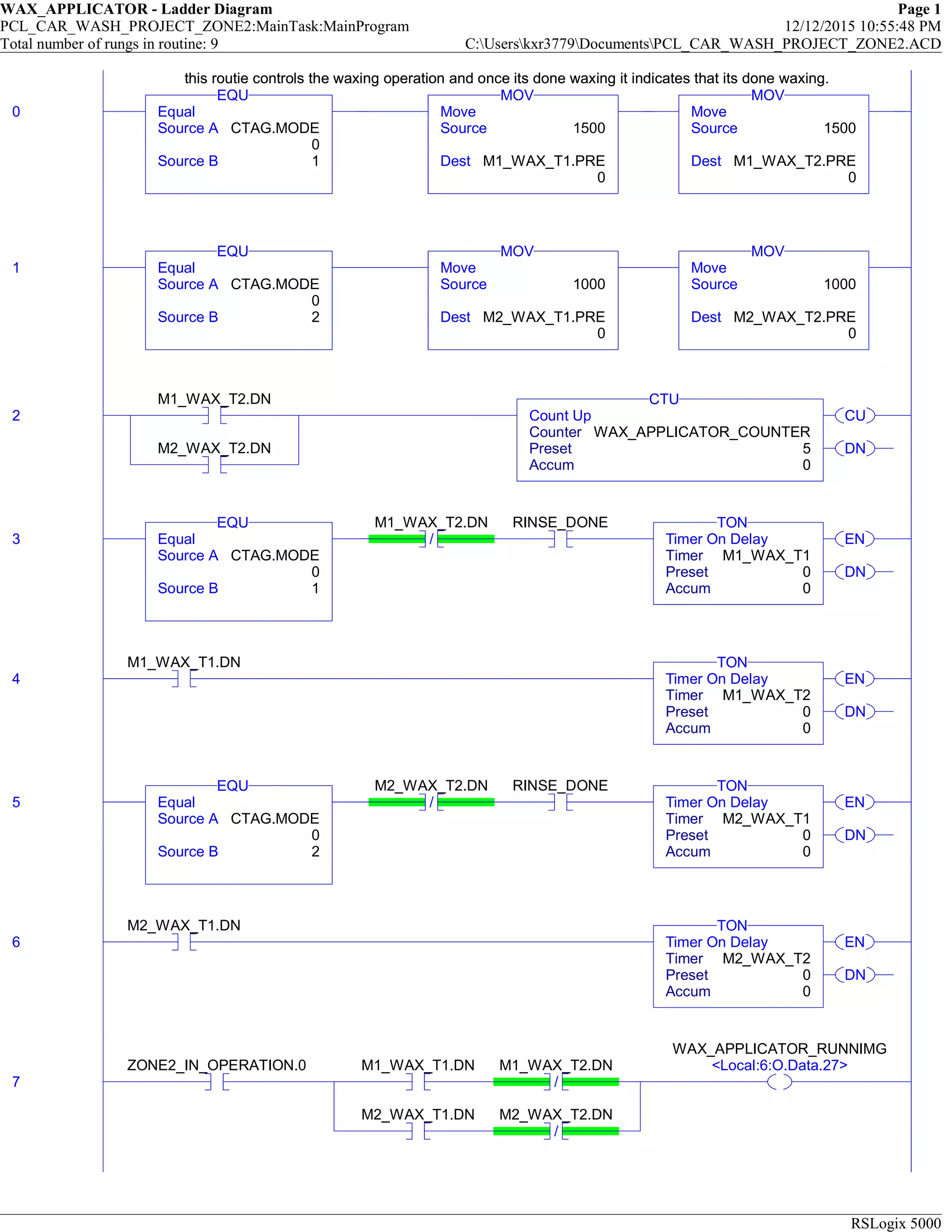
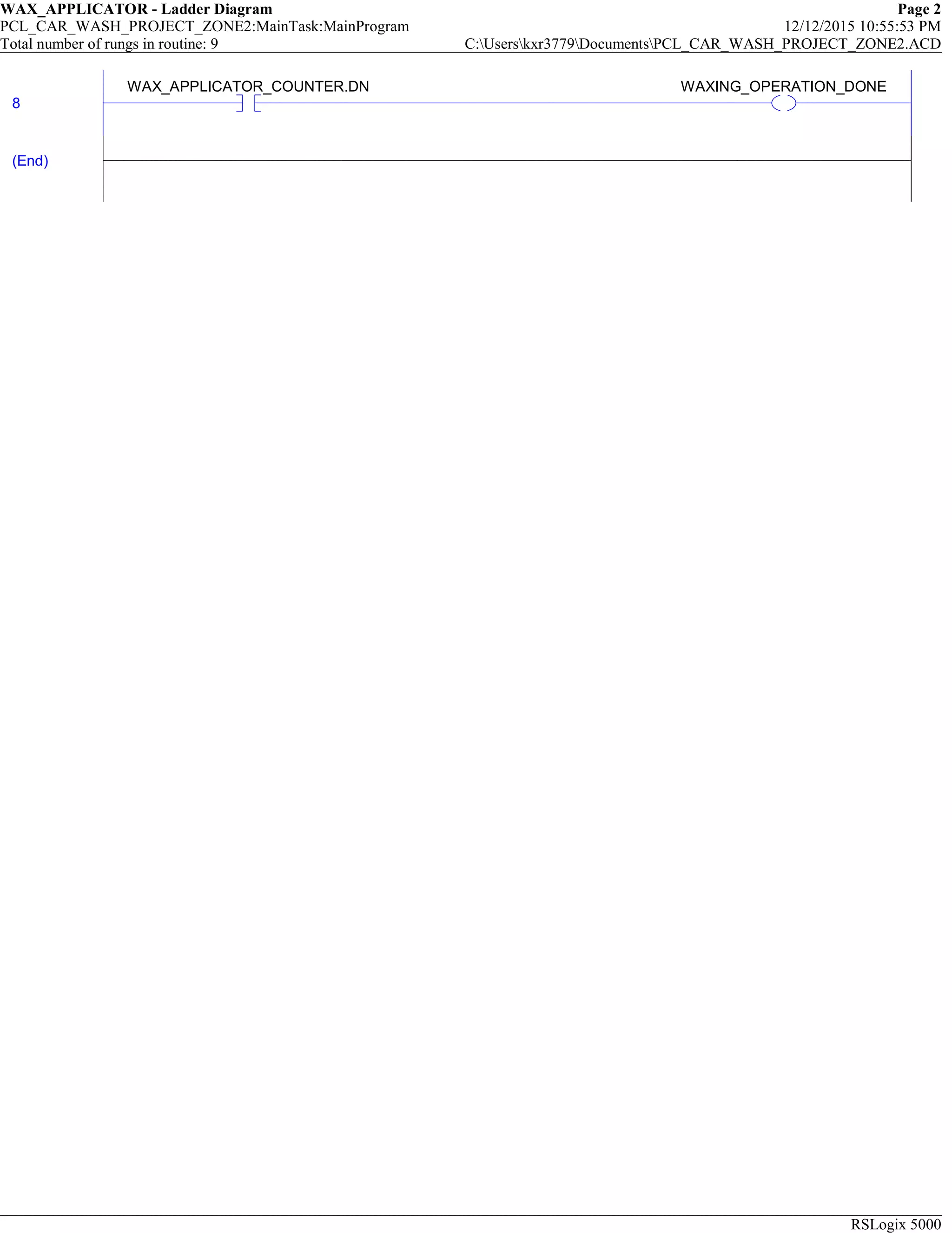
this routie controls the waxing operation and once its done waxing it indicates that its done waxing.
0 Equal
Source A CTAG.MODE
0
Source B 1
EQU
Move
Source 1500
Dest M1_WAX_T1.PRE
0
MOV
Move
Source 1500
Dest M1_WAX_T2.PRE
0
MOV
this routie controls the waxing operation and once its done waxing it indicates that its done waxing.
1 Equal
Source A CTAG.MODE
0
Source B 2
EQU
Move
Source 1000
Dest M2_WAX_T1.PRE
0
MOV
Move
Source 1000
Dest M2_WAX_T2.PRE
0
MOV
2
M1_WAX_T2.DN
M2_WAX_T2.DN
CU
DN
Count Up
Counter WAX_APPLICATOR_COUNTER
Preset 5
Accum 0
CTU
3 Equal
Source A CTAG.MODE
0
Source B 1
EQU
/
M1_WAX_T2.DN RINSE_DONE
EN
DN
Timer On Delay
Timer M1_WAX_T1
Preset 0
Accum 0
TON
4
M1_WAX_T1.DN
EN
DN
Timer On Delay
Timer M1_WAX_T2
Preset 0
Accum 0
TON
5 Equal
Source A CTAG.MODE
0
Source B 2
EQU
/
M2_WAX_T2.DN RINSE_DONE
EN
DN
Timer On Delay
Timer M2_WAX_T1
Preset 0
Accum 0
TON
6
M2_WAX_T1.DN
EN
DN
Timer On Delay
Timer M2_WAX_T2
Preset 0
Accum 0
TON
7
ZONE2_IN_OPERATION.0 M1_WAX_T1.DN
/
M1_WAX_T2.DN
M2_WAX_T1.DN
/
M2_WAX_T2.DN
WAX_APPLICATOR_RUNNIMG
<Local:6:O.Data.27>
23.
WAX_APPLICATOR - LadderDiagram Page 2
PCL_CAR_WASH_PROJECT_ZONE2:MainTask:MainProgram 12/12/2015 10:55:53 PM
Total number of rungs in routine: 9 C:Userskxr3779DocumentsPCL_CAR_WASH_PROJECT_ZONE2.ACD
RSLogix 5000
8
WAX_APPLICATOR_COUNTER.DN WAXING_OPERATION_DONE
(End)
24.
DRYER - LadderDiagram Page 1
PCL_CAR_WASH_PROJECT_ZONE2:MainTask:MainProgram 12/12/2015 10:57:03 PM
Total number of rungs in routine: 4 C:Userskxr3779DocumentsPCL_CAR_WASH_PROJECT_ZONE2.ACD
RSLogix 5000
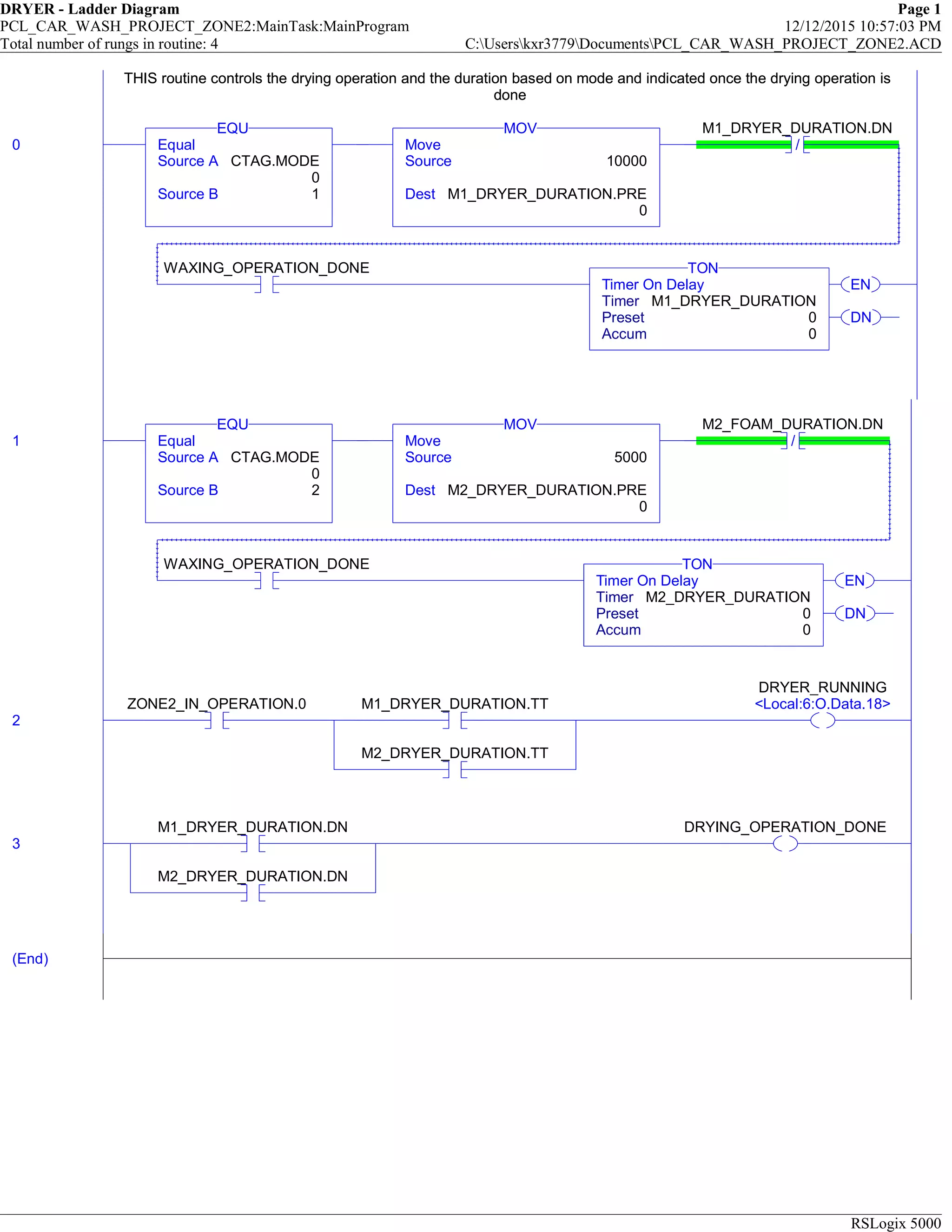
THIS routine controls the drying operation and the duration based on mode and indicated once the drying operation is
done
0 Equal
Source A CTAG.MODE
0
Source B 1
EQU
Move
Source 10000
Dest M1_DRYER_DURATION.PRE
0
MOV
/
M1_DRYER_DURATION.DN
WAXING_OPERATION_DONE
EN
DN
Timer On Delay
Timer M1_DRYER_DURATION
Preset 0
Accum 0
TON
THIS routine controls the drying operation and the duration based on mode and indicated once the drying operation is
done
1 Equal
Source A CTAG.MODE
0
Source B 2
EQU
Move
Source 5000
Dest M2_DRYER_DURATION.PRE
0
MOV
/
M2_FOAM_DURATION.DN
WAXING_OPERATION_DONE
EN
DN
Timer On Delay
Timer M2_DRYER_DURATION
Preset 0
Accum 0
TON
2
ZONE2_IN_OPERATION.0 M1_DRYER_DURATION.TT
M2_DRYER_DURATION.TT
DRYER_RUNNING
<Local:6:O.Data.18>
3
M1_DRYER_DURATION.DN
M2_DRYER_DURATION.DN
DRYING_OPERATION_DONE
(End)


![Waching machine[1]](https://cdn.slidesharecdn.com/ss_thumbnails/wachingmachine1-190420045344-thumbnail.jpg?width=640&height=640&fit=bounds)