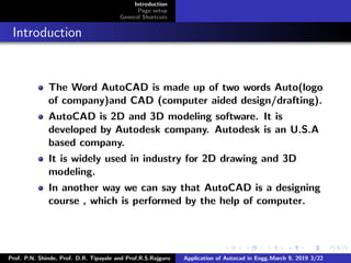
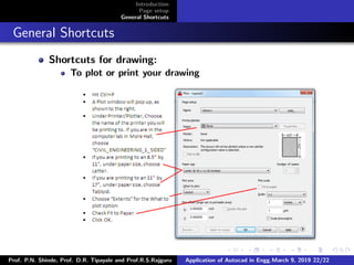
The document provides an overview of AutoCAD and describes various shortcuts and commands for page setup, drawing, and editing in AutoCAD. It introduces AutoCAD as 2D and 3D modeling software widely used in engineering and outlines shortcuts for common tasks like saving files, undoing/redoing actions, and copying/pasting. The document also lists commands for setting up pages, units and drawing styles as well as shortcuts for drawing, editing, and arranging objects in AutoCAD drawings.
Every engineer communicates with a common language called "Engineering Drawings". The technique of producing engineering drawings is DRAFTING. AutoCAD is used as a defacto standard for Drafting worldwide.
The course explores the latest tools and techniques of the software package covering all draw commands and options, editing, dimensioning, hatching, and plotting techniques available with AutoCAD Training. The textbook, helps in advancing the frontiers of the software, takes the user across a wide spectrum of engineering solutions through progressive examples, comprehensive illustrations, and detailed exercises, thereby making it an ideal solution for both the novice and the advanced user.
I have made this when I was learning AutoCAD. There are command details, what they are used for and suitable example to see how the command works.
Hope it will be useful for beginners.
License: Trialware
Developed by: Autodesk
Stable release: 2020 / March 28, 2019; 6 months ago
Initial release date: December 1982
Operating system: Windows, macOS, iOS, Android
Available in: English Language, German language, MORE
AutoCAD is a computer-aided drawing application used for creating blue-prints for buildings, Create a bridges and computer chips. CAD is mainly used by draftsman, although engineer, surveyors and architecture, may need to use the software application.
Solid Modeling Assignment EGR 201-100 Spring 2018 .docxwhitneyleman54422
Solid Modeling Assignment
EGR 201-100
Spring 2018
Extra Credit Value: Equal to 2 homework assignments or in-class quizzes.
Due Date: March 19th by Midnight.
Assignment:
1) Using CAD (computer aided design) software, reproduce the four technical drawings.
2) Complete the survey.
3) Submit documents by email to [email protected]
Note: if you have access to Solidworks or another program and wish to use it instead, then produce the
four technical drawings and turn them in for full credit. You don’t have to use FreeCAD.
Note: the survey is part of the grade, so make sure you fill it out.
Table of Contents
Purpose of this Assignment .................................................................................................... 2
Background on Solid Modeling ............................................................................................... 2
Software Installation ............................................................................................................. 3
Assignment ........................................................................................................................... 4
Survey ................................................................................................................................... 8
Tutorial and Creating Part 1 ................................................................................................... 9
Step One - Base ............................................................................................................................ 10
Step Two – Top Notches ............................................................................................................... 14
Step Three - Extrusion .................................................................................................................. 17
Step Four – Center Hole ................................................................................................................ 18
Remove Duplicated Volumes ........................................................................................................ 20
Produce Technical Drawing ........................................................................................................... 20
Purpose of this Assignment
By drawing 3D models and producing technical drawings, you will learn to interpret x,y,z coordinates on
engineering drawings, such as those found in the Engineering Statics textbook.
Background on Solid Modeling
CAD software generally fit into one of two categories:
Solid modeling - modeling solid shapes (volumes). Materials are clearly defined.
Surface modeling - modeling wireframes and surfaces, which are hollow.
Solid modeling is clearly useful if we want to investigate stresses and strains in our designs. You
can draw solid volumes, assign material properties (wood, brick, steel, glass, aluminum), and then
subject them to loads. Generally, most.
B7rifubd d f6r f 66 d6b 6e6e6 ed6vyevyd y d ydy dysh d ydy ydy dvuovkvig.ih jvbkkbbibkv kvivibk j j I. J hi i ivy ih ih hi 8h h hy ooh oh h.o i ih hi y8 9u ih ih ih. Ih ihbcjvjvigg. Jgj gj gj fu gi fuf j ffj. Gi.g I gi i.
AutoCAD is a 2D and 3D computer desi.pptxinnocentvk155
AutoCAD is a 2D and 3D computer-aided design (CAD) software application developed by Autodesk.[1] It was first released in December 1982 for the CP/M and IBM PC platforms as a desktop app running on microcomputers with internal graphics controllers.
About
Indigenized remote control interface card suitable for MAFI system CCR equipment. Compatible for IDM8000 CCR. Backplane mounted serial and TCP/Ethernet communication module for CCR remote access. IDM 8000 CCR remote control on serial and TCP protocol.
• Remote control: Parallel or serial interface.
• Compatible with MAFI CCR system.
• Compatible with IDM8000 CCR.
• Compatible with Backplane mount serial communication.
• Compatible with commercial and Defence aviation CCR system.
• Remote control system for accessing CCR and allied system over serial or TCP.
• Indigenized local Support/presence in India.
• Easy in configuration using DIP switches.
Technical Specifications
Indigenized remote control interface card suitable for MAFI system CCR equipment. Compatible for IDM8000 CCR. Backplane mounted serial and TCP/Ethernet communication module for CCR remote access. IDM 8000 CCR remote control on serial and TCP protocol.
Key Features
Indigenized remote control interface card suitable for MAFI system CCR equipment. Compatible for IDM8000 CCR. Backplane mounted serial and TCP/Ethernet communication module for CCR remote access. IDM 8000 CCR remote control on serial and TCP protocol.
• Remote control: Parallel or serial interface
• Compatible with MAFI CCR system
• Copatiable with IDM8000 CCR
• Compatible with Backplane mount serial communication.
• Compatible with commercial and Defence aviation CCR system.
• Remote control system for accessing CCR and allied system over serial or TCP.
• Indigenized local Support/presence in India.
Application
• Remote control: Parallel or serial interface.
• Compatible with MAFI CCR system.
• Compatible with IDM8000 CCR.
• Compatible with Backplane mount serial communication.
• Compatible with commercial and Defence aviation CCR system.
• Remote control system for accessing CCR and allied system over serial or TCP.
• Indigenized local Support/presence in India.
• Easy in configuration using DIP switches.
Cosmetic shop management system project report.pdfKamal Acharya
Buying new cosmetic products is difficult. It can even be scary for those who have sensitive skin and are prone to skin trouble. The information needed to alleviate this problem is on the back of each product, but it's thought to interpret those ingredient lists unless you have a background in chemistry.
Instead of buying and hoping for the best, we can use data science to help us predict which products may be good fits for us. It includes various function programs to do the above mentioned tasks.
Data file handling has been effectively used in the program.
The automated cosmetic shop management system should deal with the automation of general workflow and administration process of the shop. The main processes of the system focus on customer's request where the system is able to search the most appropriate products and deliver it to the customers. It should help the employees to quickly identify the list of cosmetic product that have reached the minimum quantity and also keep a track of expired date for each cosmetic product. It should help the employees to find the rack number in which the product is placed.It is also Faster and more efficient way.
Sachpazis:Terzaghi Bearing Capacity Estimation in simple terms with Calculati...Dr.Costas Sachpazis
Terzaghi's soil bearing capacity theory, developed by Karl Terzaghi, is a fundamental principle in geotechnical engineering used to determine the bearing capacity of shallow foundations. This theory provides a method to calculate the ultimate bearing capacity of soil, which is the maximum load per unit area that the soil can support without undergoing shear failure. The Calculation HTML Code included.
CFD Simulation of By-pass Flow in a HRSG module by R&R Consult.pptxR&R Consult
CFD analysis is incredibly effective at solving mysteries and improving the performance of complex systems!
Here's a great example: At a large natural gas-fired power plant, where they use waste heat to generate steam and energy, they were puzzled that their boiler wasn't producing as much steam as expected.
R&R and Tetra Engineering Group Inc. were asked to solve the issue with reduced steam production.
An inspection had shown that a significant amount of hot flue gas was bypassing the boiler tubes, where the heat was supposed to be transferred.
R&R Consult conducted a CFD analysis, which revealed that 6.3% of the flue gas was bypassing the boiler tubes without transferring heat. The analysis also showed that the flue gas was instead being directed along the sides of the boiler and between the modules that were supposed to capture the heat. This was the cause of the reduced performance.
Based on our results, Tetra Engineering installed covering plates to reduce the bypass flow. This improved the boiler's performance and increased electricity production.
It is always satisfying when we can help solve complex challenges like this. Do your systems also need a check-up or optimization? Give us a call!
Work done in cooperation with James Malloy and David Moelling from Tetra Engineering.
More examples of our work https://www.r-r-consult.dk/en/cases-en/
Overview of the fundamental roles in Hydropower generation and the components involved in wider Electrical Engineering.
This paper presents the design and construction of hydroelectric dams from the hydrologist’s survey of the valley before construction, all aspects and involved disciplines, fluid dynamics, structural engineering, generation and mains frequency regulation to the very transmission of power through the network in the United Kingdom.
Author: Robbie Edward Sayers
Collaborators and co editors: Charlie Sims and Connor Healey.
(C) 2024 Robbie E. Sayers
1. Introduction
Page setup
General Shortcuts
Application of Autocad in Engineering
[Prof. P.N. Shinde, Prof. D.R. Tipayale and
Prof.R.S.Rajguru
Civil Engineering Department
SRES COE KOPERGAON
March 9, 2019
Prof. P.N. Shinde, Prof. D.R. Tipayale and Prof.R.S.Rajguru Application of Autocad in Engg.March 9, 2019 1/22
2. Introduction
Page setup
General Shortcuts
Table of Content
1 Introduction
2 Page setup
3 General Shortcuts
Prof. P.N. Shinde, Prof. D.R. Tipayale and Prof.R.S.Rajguru Application of Autocad in Engg.March 9, 2019 2/22
3. Introduction
Page setup
General Shortcuts
Introduction
The Word AutoCAD is made up of two words Auto(logo
of company)and CAD (computer aided design/drafting).
AutoCAD is 2D and 3D modeling software. It is
developed by Autodesk company. Autodesk is an U.S.A
based company.
It is widely used in industry for 2D drawing and 3D
modeling.
In another way we can say that AutoCAD is a designing
course , which is performed by the help of computer.
Prof. P.N. Shinde, Prof. D.R. Tipayale and Prof.R.S.Rajguru Application of Autocad in Engg.March 9, 2019 3/22
4. Introduction
Page setup
General Shortcuts
Page setup
Open new page and save new page
1. Choose File, New.
or 2. Press CTRL + N
or 3. Click the New icon.
or 4. Save the drawing as another name.
Command: SAVE or SAVEAS Press ENTER
Type A new drawing name or keep the existing drawing
name
Prof. P.N. Shinde, Prof. D.R. Tipayale and Prof.R.S.Rajguru Application of Autocad in Engg.March 9, 2019 4/22
6. Introduction
Page setup
General Shortcuts
Set Units
Command: DDUNITS or UN Choosea units and angle
setting.
Choosea precision setting.
After set units and Limits press(Z) enter (A) enter
.
Prof. P.N. Shinde, Prof. D.R. Tipayale and Prof.R.S.Rajguru Application of Autocad in Engg.March 9, 2019 6/22
8. Introduction
Page setup
General Shortcuts
Set New Dimension Style
Command:DDIM
Prof. P.N. Shinde, Prof. D.R. Tipayale and Prof.R.S.Rajguru Application of Autocad in Engg.March 9, 2019 8/22
9. Introduction
Page setup
General Shortcuts
Set New Text Style
Command: TEXT
Prof. P.N. Shinde, Prof. D.R. Tipayale and Prof.R.S.Rajguru Application of Autocad in Engg.March 9, 2019 9/22
10. Introduction
Page setup
General Shortcuts
General Shortcuts
General Shortcuts:
Ctrl+S saves the dwg file
Ctrl+Z undoes the previous action
Ctrl+Y redoes the action
Ctrl+C and Ctrl+V copies and pastes, respectively
Ctrl+P to plot
Prof. P.N. Shinde, Prof. D.R. Tipayale and Prof.R.S.Rajguru Application of Autocad in Engg.March 9, 2019 10/22
11. Introduction
Page setup
General Shortcuts
Shortcuts for drawing:
POINT (po) draws a point at anywhere you specify
by clicking on the location or
by typing in the x-coordinate, tab, typing in the
y-coordinate.
Line (l) draws a line from one point to another.
Polyline (pl) draws a line/curve with multiple control
points.
Rectangle draws a rectangle with two corners specified.
Click to designate first corner of the rectangle.
Click again to designate the opposite corner of the
rectangle
Prof. P.N. Shinde, Prof. D.R. Tipayale and Prof.R.S.Rajguru Application of Autocad in Engg.March 9, 2019 11/22
12. Introduction
Page setup
General Shortcuts
Shortcuts for drawing:
Hatch (h) adds hatch patterns or fills to an enclosed
area or to selected objects.
Prof. P.N. Shinde, Prof. D.R. Tipayale and Prof.R.S.Rajguru Application of Autocad in Engg.March 9, 2019 12/22
13. Introduction
Page setup
General Shortcuts
Shortcuts for drawing:
Divide (div) divides a selected object into certain length
or perimeter segment. You can draw from the node or
you can place objects along the nodes (place trees 20
feet from each other on a sidewalk down a street).
Select the object to divide
Enter the number of segments
Erase (e): erases the selected objects. You can get the
same effect by selecting objects and hitting Delete.
Prof. P.N. Shinde, Prof. D.R. Tipayale and Prof.R.S.Rajguru Application of Autocad in Engg.March 9, 2019 13/22
14. Introduction
Page setup
General Shortcuts
Shortcuts for drawing:
Copy (cp): copies the selected objects from one place to
another Select the object(s)
Click or enter in the coordinates for your base point.
Choose the second point, which will be where you want
the copied object to go
Move (m): moves your selected objects from one place
to another
Select the object(s)
Choose your base point.
Choose the point to move it to.
Prof. P.N. Shinde, Prof. D.R. Tipayale and Prof.R.S.Rajguru Application of Autocad in Engg.March 9, 2019 14/22
15. Introduction
Page setup
General Shortcuts
Shortcuts for drawing:
Mirror (mi): mirrors objects along the line that you
define.
Select your object(s). Hit enter when all of them are
selected
Pick your first point, and then pick the end point of the
mirror line.
It will prompt you to erase the original object. Type y for
yes or n for no.
Offset (o): offsets objects to the distance of your choice
It will prompt you for a distance to offset first. Enter in
that number or click two points on the screen giving the
distance that you want.
Pick the object that you want to offset and then choose
the side you want to offset it.
Prof. P.N. Shinde, Prof. D.R. Tipayale and Prof.R.S.Rajguru Application of Autocad in Engg.March 9, 2019 15/22
16. Introduction
Page setup
General Shortcuts
Shortcuts for drawing:
Scale (sc): scales objects by a given ratio
Select the objects
Click or enter in the base point
Click or enter in the scale numerically
Explode (x): break selected complex objects such as
blocks and polylines down to lines and arcs.
Select the blocks or polylines you want to explode.
Hit esc to finish. Select objects to ensure they were
successfully broken down. You should multiple end points
for lines and arcs if successful.
Prof. P.N. Shinde, Prof. D.R. Tipayale and Prof.R.S.Rajguru Application of Autocad in Engg.March 9, 2019 16/22
17. Introduction
Page setup
General Shortcuts
Shortcuts for drawing:
Trim (tr): trim objects using specified objects
Using the following image as an example, select the
object you want to use as the trimmer. you select the
line first. And hit enter.
Then choose the side you want to trim of the object you
will be trimming.
Prof. P.N. Shinde, Prof. D.R. Tipayale and Prof.R.S.Rajguru Application of Autocad in Engg.March 9, 2019 17/22
18. Introduction
Page setup
General Shortcuts
Shortcuts for drawing:
Extend (ex): extend objects to reach specified objects
Using the images below, select the object that you want
to extend to. In this case, if you wanted to extend the
horizontal line to the vertical line, you would select the
vertical line first. Then hit enter. Then choose the object
you want to extend, which in this case would be the
horizontal line itself. The line will extend immediately.
Prof. P.N. Shinde, Prof. D.R. Tipayale and Prof.R.S.Rajguru Application of Autocad in Engg.March 9, 2019 18/22
19. Introduction
Page setup
General Shortcuts
Shortcuts for drawing:
Break (br): makes cuts through continuous lines.
Select the object by choosing where you want the break
to start and then click where you want the break to end.
Keep in mind that if youre breaking a non-close shape,
the break occurs between the two points (i.e. a line). If
its a closed shape, the portion that will be kept is going
to be the portion between the points moving
counterclockwise as shown below.
Prof. P.N. Shinde, Prof. D.R. Tipayale and Prof.R.S.Rajguru Application of Autocad in Engg.March 9, 2019 19/22
20. Introduction
Page setup
General Shortcuts
Shortcuts for drawing:
Block: group of objects joined together as one entity.
Prof. P.N. Shinde, Prof. D.R. Tipayale and Prof.R.S.Rajguru Application of Autocad in Engg.March 9, 2019 20/22
21. Introduction
Page setup
General Shortcuts
General Shortcuts
Shortcuts for drawing:
To plot or print your drawing
switch Paper Space by clicking the Layout tab at the
bottom of the screen.
Prof. P.N. Shinde, Prof. D.R. Tipayale and Prof.R.S.Rajguru Application of Autocad in Engg.March 9, 2019 21/22
22. Introduction
Page setup
General Shortcuts
General Shortcuts
Shortcuts for drawing:
To plot or print your drawing
Prof. P.N. Shinde, Prof. D.R. Tipayale and Prof.R.S.Rajguru Application of Autocad in Engg.March 9, 2019 22/22