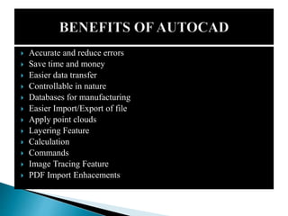
 INTRODUCTION
 LATEST VERSION
 AUTOCAD SCREEN
 WAYS TO PROVIDE COMMAND
 HOW IT WORKS
 CO – ORDINATE SYSTEM
 TOOLBARS
 SOME 2D COMMAND
 3D MODELLING
 SOME 3D COMMAND
 ISOMETRIC VIEW
 PROJECT WORK
 BENEFITS OF AUTOCAD
 AutoCAD is an industry-leading commercial CAD software.
 AutoCAD is used by AEC(Architecture, Engineer, and
Construction) to generate and optimize 2D and 3D designs.
AutoCAD is a widely used software program that can help
you draft construction documentation, explore design ideas,
visualize concepts through photorealistic renderings, and
simulate how a design performs in the real world. (Autodesk)
 AutoCAD was first released in December 1982 as a desktop
app. In 2010, AutoCAD was released as a mobile- and web
app, marketed as AutoCAD 360. (Autodesk and AutoCAD)
VERSION
1. AUTOCAD 2020
2. AUTOCAD 2019
3. AUTOCAD 2018
DESCRIPTION
1) The features included are block palettes,
enhanced DWG, drawing annotation, quick
measurements, cloud storage connectivity,
etc.
2) The features included are Map 3D,
Mechanical design, electrical design,
architecture, new AutoCAD web and mobile
app, raster design, and MEP (Mechanical
Electrical Pumping).
3) The features included are Map 3D,
Mechanical design, electrical design,
architecture, new AutoCAD web and
mobile app, raster design, and MEP
(Mechanical Electrical Pumping).
 Application menu: New, open, save, import, export, print
 Quick access toolbar: User can save tools that they often use
 Info Center: Ask a question, find out answers from Autodesk community
 Ribbon: Main menus – Home, Insert, Annotate, View, Manage
 Ribbon tab
 Ribbon view: User can minimize and maximize the ribbon
 File tab: Navigate files and create and open files
 Drawing area/graphic area: Main drawing space
 View cube: User can change the view, top, front, 3D, or more
 Navigation bar: Zoom in and out, pan, zoon to all, and more
 Command box: Can type commands and see the previous commands
 Layout tab: Can see model space and print spaces
 Status bar: Can set grid, snaps, scales, and more
AutoCAD allows users to use lines, polygons,
shapes, text and other visual items to create scale-
model blueprints of whatever structure they
happen to be designing. This is incredibly
important to the process of building, as someone
well-versed in the workings of AutoCAD can
provide a blueprint accurate down to the
millimeter. Newer versions of AutoCAD also allow
the user to see the finished blueprint design in
three dimensions, adding to the program's overall
usefulness to design and construction.
There are two coordinate systems in
AutoCAD. World Coordinate System (WCS)
and User Coordinate System (UCS) which define
the angle of the XY plane you are working in.
The WCS should always be used to reference
geometry to ensure everything aligns to the centre of
a file in real-world location. The UCS can be used to
orientate the screen to a site.Drawing files will
usually have the WCS set by default.The
current WCS or UCS orientation is indicated by
the UCS icon in the bottom left corner of the screen.
 Toolbars provide one of several customizable ways to start
commands and change settings.
 Types of Toolbars
 Toolbars contain buttons that start commands. Buttons with a
small black triangle in the lower-right corner are flyout
toolbars that contain related commands. With the cursor over
the icon, hold down the left button on your mouse until the
flyout toolbar displays.
 The Quick Access toolbar at the top of the application window
is displayed by default. It contains frequently used commands
as well as standard commands for opening and saving your
file.
 LINE and POLYLINE
 ARC
 RECTANGLE
 CIRCLE
 SCALE
 TRIM
 ERASE
 TEXT
 MOVE
 COPY
 ROTATE
The process of creating a mathematical
representation of any surface of an object in
three dimensions by using special software is
called 3D modeling. A 3D model can even be
represented as a two-dimensional image by
using the 3D rendering process. The user can
also create 3D models physically using 3D
printers.
 3DMOVE (Command)
 3DORBIT (Command)
 3DROTATE (Command)
 3DSCALE (Command)
 BOX (Command)
 CONE (Command)
 CONVTOMESH (Command)
 CONVTONURBS (Command)
 CONVTOSOLID (Command)
 CONVTOSURFACE (Command)
 CYLINDER (Command)
 EXTRUDE (Command)
 LOFT (Command)
 MESH (Command)
 PLANESURF (Command)
 POLYSOLID (Command)
 PROJECTGEOMETRY (Command)
 PROPERTIES (Command)
 PYRAMID (Command)
 REGEN3 (Command)
 REVOLVE (Command)
 ROTATE (Command)
 SPHERE (Command)
 SURFBLEND (Command)
 SURFNETWORK (Command)
 SURFOFFSET (Command)
 SURFPATCH (Command)
 SWEEP (Command)
 TORUS (Command)
 UCS (Command)
 VPORTS (Command)
 WEDGE (Command)
 A 2D isometric drawing, which may be created from
an isometric projection, is a flat representation of a 3D
isometric projection. This method of drawing provides a fast
way to create an isometric view of a simple design. Distances
measured along an isometric axis are correct to scale. But
because you are drawing in 2D, you cannot expect to extract
other 3D distances and areas, display objects from different
viewpoints, or remove hidden lines automatically.
 Before the advent of CAD, we created isometric drawings
with our T-square (or drafting arm) and our trusty 30-60-90
triangle. But you can accomplish the same thing in AutoCAD
 Accurate and reduce errors
 Save time and money
 Easier data transfer
 Controllable in nature
 Databases for manufacturing
 Easier Import/Export of file
 Apply point clouds
 Layering Feature
 Calculation
 Commands
 Image Tracing Feature
 PDF Import Enhacements
END OF PRESENTATION

AUTOCAD REPORT.pptx

  • 2.
     INTRODUCTION  LATESTVERSION  AUTOCAD SCREEN  WAYS TO PROVIDE COMMAND  HOW IT WORKS  CO – ORDINATE SYSTEM  TOOLBARS  SOME 2D COMMAND  3D MODELLING  SOME 3D COMMAND  ISOMETRIC VIEW  PROJECT WORK  BENEFITS OF AUTOCAD
  • 3.
     AutoCAD isan industry-leading commercial CAD software.  AutoCAD is used by AEC(Architecture, Engineer, and Construction) to generate and optimize 2D and 3D designs. AutoCAD is a widely used software program that can help you draft construction documentation, explore design ideas, visualize concepts through photorealistic renderings, and simulate how a design performs in the real world. (Autodesk)  AutoCAD was first released in December 1982 as a desktop app. In 2010, AutoCAD was released as a mobile- and web app, marketed as AutoCAD 360. (Autodesk and AutoCAD)
  • 4.
    VERSION 1. AUTOCAD 2020 2.AUTOCAD 2019 3. AUTOCAD 2018 DESCRIPTION 1) The features included are block palettes, enhanced DWG, drawing annotation, quick measurements, cloud storage connectivity, etc. 2) The features included are Map 3D, Mechanical design, electrical design, architecture, new AutoCAD web and mobile app, raster design, and MEP (Mechanical Electrical Pumping). 3) The features included are Map 3D, Mechanical design, electrical design, architecture, new AutoCAD web and mobile app, raster design, and MEP (Mechanical Electrical Pumping).
  • 6.
     Application menu:New, open, save, import, export, print  Quick access toolbar: User can save tools that they often use  Info Center: Ask a question, find out answers from Autodesk community  Ribbon: Main menus – Home, Insert, Annotate, View, Manage  Ribbon tab  Ribbon view: User can minimize and maximize the ribbon  File tab: Navigate files and create and open files  Drawing area/graphic area: Main drawing space  View cube: User can change the view, top, front, 3D, or more  Navigation bar: Zoom in and out, pan, zoon to all, and more  Command box: Can type commands and see the previous commands  Layout tab: Can see model space and print spaces  Status bar: Can set grid, snaps, scales, and more
  • 7.
    AutoCAD allows usersto use lines, polygons, shapes, text and other visual items to create scale- model blueprints of whatever structure they happen to be designing. This is incredibly important to the process of building, as someone well-versed in the workings of AutoCAD can provide a blueprint accurate down to the millimeter. Newer versions of AutoCAD also allow the user to see the finished blueprint design in three dimensions, adding to the program's overall usefulness to design and construction.
  • 8.
    There are twocoordinate systems in AutoCAD. World Coordinate System (WCS) and User Coordinate System (UCS) which define the angle of the XY plane you are working in. The WCS should always be used to reference geometry to ensure everything aligns to the centre of a file in real-world location. The UCS can be used to orientate the screen to a site.Drawing files will usually have the WCS set by default.The current WCS or UCS orientation is indicated by the UCS icon in the bottom left corner of the screen.
  • 9.
     Toolbars provideone of several customizable ways to start commands and change settings.  Types of Toolbars  Toolbars contain buttons that start commands. Buttons with a small black triangle in the lower-right corner are flyout toolbars that contain related commands. With the cursor over the icon, hold down the left button on your mouse until the flyout toolbar displays.  The Quick Access toolbar at the top of the application window is displayed by default. It contains frequently used commands as well as standard commands for opening and saving your file.
  • 10.
     LINE andPOLYLINE  ARC  RECTANGLE  CIRCLE  SCALE  TRIM  ERASE  TEXT  MOVE  COPY  ROTATE
  • 11.
    The process ofcreating a mathematical representation of any surface of an object in three dimensions by using special software is called 3D modeling. A 3D model can even be represented as a two-dimensional image by using the 3D rendering process. The user can also create 3D models physically using 3D printers.
  • 12.
     3DMOVE (Command) 3DORBIT (Command)  3DROTATE (Command)  3DSCALE (Command)  BOX (Command)  CONE (Command)  CONVTOMESH (Command)  CONVTONURBS (Command)  CONVTOSOLID (Command)  CONVTOSURFACE (Command)  CYLINDER (Command)  EXTRUDE (Command)  LOFT (Command)  MESH (Command)  PLANESURF (Command)  POLYSOLID (Command)  PROJECTGEOMETRY (Command)  PROPERTIES (Command)  PYRAMID (Command)  REGEN3 (Command)  REVOLVE (Command)  ROTATE (Command)  SPHERE (Command)  SURFBLEND (Command)  SURFNETWORK (Command)  SURFOFFSET (Command)  SURFPATCH (Command)  SWEEP (Command)  TORUS (Command)  UCS (Command)  VPORTS (Command)  WEDGE (Command)
  • 13.
     A 2Disometric drawing, which may be created from an isometric projection, is a flat representation of a 3D isometric projection. This method of drawing provides a fast way to create an isometric view of a simple design. Distances measured along an isometric axis are correct to scale. But because you are drawing in 2D, you cannot expect to extract other 3D distances and areas, display objects from different viewpoints, or remove hidden lines automatically.  Before the advent of CAD, we created isometric drawings with our T-square (or drafting arm) and our trusty 30-60-90 triangle. But you can accomplish the same thing in AutoCAD
  • 15.
     Accurate andreduce errors  Save time and money  Easier data transfer  Controllable in nature  Databases for manufacturing  Easier Import/Export of file  Apply point clouds  Layering Feature  Calculation  Commands  Image Tracing Feature  PDF Import Enhacements
  • 16.