Download to read offline

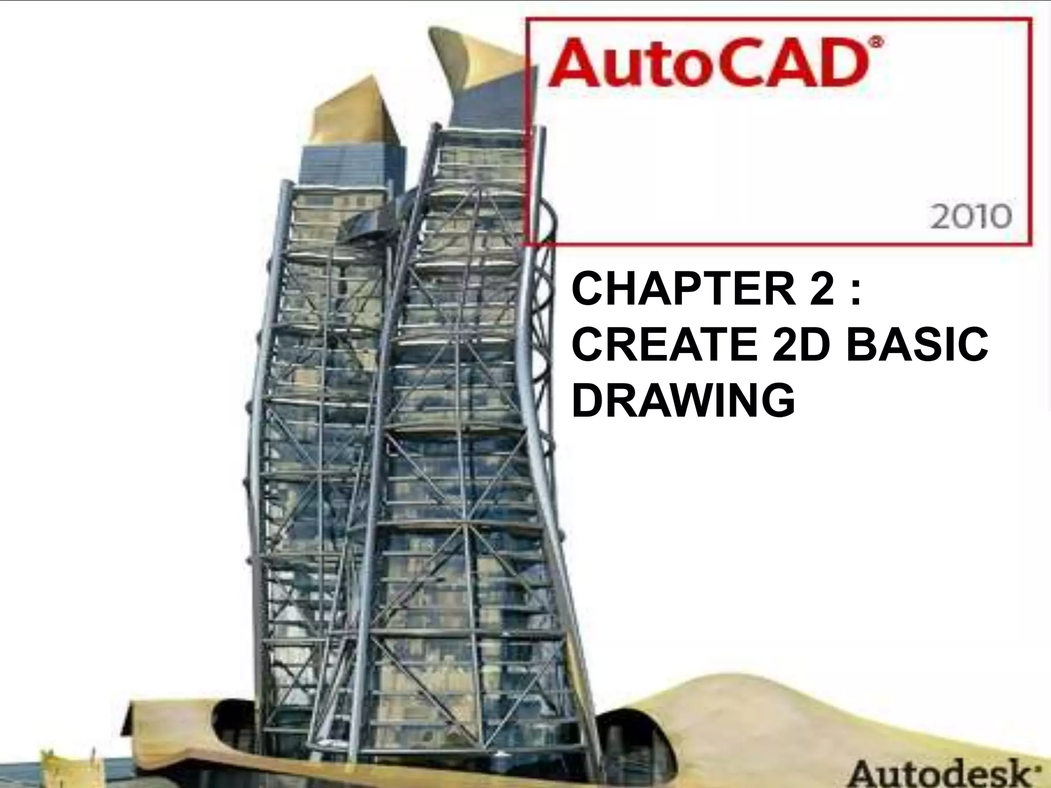

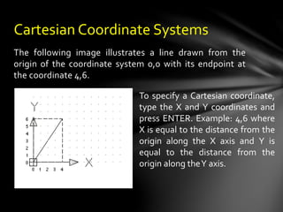
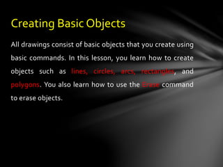
![•Command options appear on the command line. The
capitalized letter(s) represents the letter(s) you enter to use
that option. You are not required to enter the letter(s) as a
capital letter.
•Options for the command appear within [...] brackets. If
there is a default option for the command, it appears within
<...> brackets.To use the default option, press ENTER.
Command Line Options](https://image.slidesharecdn.com/chapter2-create2dbasicdrawing-230524084423-7b91de22/85/CHAPTER-2-Create-2D-Basic-Drawing-pptx-4-320.jpg)
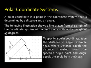
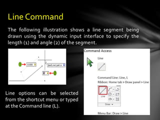
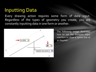
![The ENDpoint Object Snap mode
snaps to the closest endpoint of a
line or an arc. To use this Object
Snap mode, select the Endpoint
button, and move the cursor
(crosshairs) anywhere close to the
endpoint of the object. The marker
will be displayed at the endpoint;
click to specify that point. For figure,
invoke the LINE command from the
Draw toolbar. The following is the
prompt sequence:
ENDpoint Object Snap mode
Specify first point: Select the Endpoint button from the Object
Snap toolbar.
_endp of Move the crosshair and select the arc.
Specify next point or [Undo]: Select the endpoint of the line.
• Endpoint](https://image.slidesharecdn.com/chapter2-create2dbasicdrawing-230524084423-7b91de22/85/CHAPTER-2-Create-2D-Basic-Drawing-pptx-18-320.jpg)
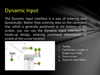
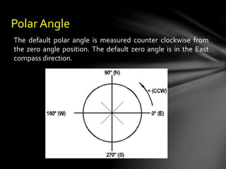
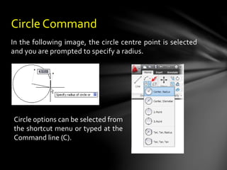
![The MIDpoint Object Snap mode snaps to the
midpoint of a line or an arc. To use this Object Snap
mode, select Midpoint osnap and select the object
anywhere. AutoCAD will grab the midpoint of the
object. For figure, invoke the LINE command from the
Draw toolbar.The following is the prompt sequence.
MIDpoint Object Snap mode
Specify first point: Select the starting point of the
line.
Specify next point or [Undo]: Choose the Snap to
Midpoint button from the Object Snap toolbar.
_mid of Move the cursor and select the original
line.
• Midpoint](https://image.slidesharecdn.com/chapter2-create2dbasicdrawing-230524084423-7b91de22/85/CHAPTER-2-Create-2D-Basic-Drawing-pptx-19-320.jpg)
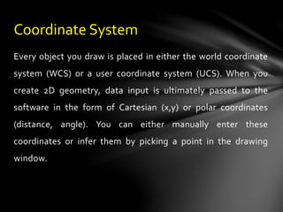
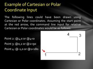
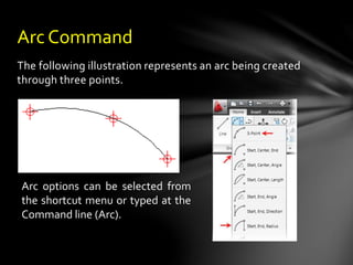
![The CENter Object Snap mode allows you to snap to the
center point of an ellipse, circle, or arc. For figure, invoke the
LINE command from the Draw toolbar. The following is the
prompt sequence:
Specify first point: Choose the Snap to Center button from the
Object Snap toolbar.
_cen of Move the cursor and select the circle.
Specify next point or [Undo]: Select the endpoint of the line.
CENter Object Snap mode
For figure, invoke the LINE command from the Draw toolbar.
The following is the prompt sequence:
Specify first point: Select the starting point of the line.
Specify next point or [Undo]: Choose the Snap to Tangent
button from the Object Snap toolbar.
_tan to Move the cursor and select the circle.
Specify next point or [Undo]: Select the endpoint of the
line (tangent of the circle).
TANgent Object Snap mode
• Center
• Tangent](https://image.slidesharecdn.com/chapter2-create2dbasicdrawing-230524084423-7b91de22/85/CHAPTER-2-Create-2D-Basic-Drawing-pptx-20-320.jpg)
![The INTersection Object Snap mode is used to snap to a point where two or more
lines, circles, ellipses, or arcs intersect. For figure, invoke the LINE command. The
prompt sequence is given next.
INTersection Object
Snap mode
Specify first point: Choose the Snap to Intersection button from the Object Snap toolbar.
_ int of Position the cursor near the intersection and select it.
Specify next point or [Undo]: Select the endpoint of the line.
After selecting the Intersection
object snap, if your cursor is close to
an object and not close to an actual
intersection, the intersection marker
displays ellipses [...] with it. This
indicates an extended intersection.
This mode selects extended or
visual intersections of lines, arcs,
circles, or ellipses (figure). Extended Intersection
Object Snap mode
• Intersection](https://image.slidesharecdn.com/chapter2-create2dbasicdrawing-230524084423-7b91de22/85/CHAPTER-2-Create-2D-Basic-Drawing-pptx-22-320.jpg)
![The PERpendicular Object Snap mode is used to draw a
line perpendicular to or from another line, or normal to or
from an arc or circle, or to an ellipse. The prompt
sequence to draw a line perpendicular to a given line
(figure) is given next.
Specify first point: Select the starting point of the line.
Specify next point or [Undo]: Choose the Snap to Perpendicular
button from the Object Snap toolbar.
_per to Select the line on which you want to draw perpendicular.
The prompt sequence for drawing a line perpendicular
from a given line (figure) is given next.
Specify first point: Choose the Snap to Perpendicular button
from the Object Snap toolbar.
_per to Select the line on which you want to draw
perpendicular.
Specify next point or [Undo]: Select the endpoint of the line.
PERpendicular Object Snap
mode
Selecting the perpendicular
snap first
• Perpendicular](https://image.slidesharecdn.com/chapter2-create2dbasicdrawing-230524084423-7b91de22/85/CHAPTER-2-Create-2D-Basic-Drawing-pptx-23-320.jpg)
![The NEArest Object Snap mode selects a point on
an object (line, arc, circle, or ellipse) that is visually
closest to the graphics cursor (crosshairs). To use
this mode, enter the command, and then choose
the Nearest object snap. Move the crosshairs near
the intended point on the object so as to display
the marker at the desired point and then select the
object. For figure, invoke the LINE command from
the Draw toolbar. The following is the prompt
sequence: NEArest Object Snap mode
Specify first point: Choose the Snap to Nearest button
from the Object Snap toolbar.
_nea to Select a point near an existing object.
Specify next point or [Undo]: Select endpoint of the line.
• Nearest](https://image.slidesharecdn.com/chapter2-create2dbasicdrawing-230524084423-7b91de22/85/CHAPTER-2-Create-2D-Basic-Drawing-pptx-24-320.jpg)


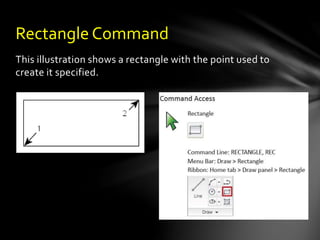
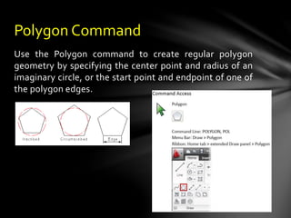
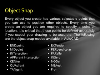
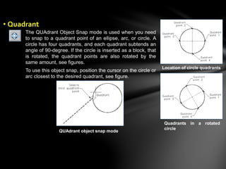
This document discusses how to create basic 2D drawings in AutoCAD, including: - Using coordinate systems, object snaps, and dynamic input to accurately place lines, circles, arcs, rectangles, and polygons. - The main drawing tools covered are the Line, Circle, Arc, Rectangle, Polygon commands as well as the Erase command. - Object snaps like Endpoint, Midpoint, Center, Tangent, and Perpendicular allow placing objects precisely relative to other existing geometry.


![Resume Taufik [07-07-15]](https://cdn.slidesharecdn.com/ss_thumbnails/b40cdf3a-33c1-4766-9b2f-b906cca0197c-150722110217-lva1-app6891-thumbnail.jpg?width=640&height=640&fit=bounds)


