Assign3
•Download as DOCX, PDF•
0 likes•133 views
The document summarizes the frame structure of SDH (Synchronous Digital Hierarchy) transmission. It explains that an STM-1 frame comprises 9 rows and 270 columns, with each column representing 1 byte. Transmission occurs row by row at a rate of 125 microseconds per frame. This equates to a payload data rate of 155.52 Mbps. It also lists the various network elements in SDH such as multiplexers, regenerators, and the SDH multiplexing process.
Report
Share
Report
Share

Recommended
Token bus
The document discusses Token Bus, which combines features of Ethernet and Token Ring. It operates as a physical bus but with stations logically organized into a ring, passing a token among them. Only the station holding the token can transmit data. Token Bus was limited to industrial applications and saw no commercial use for data communication. It uses the token passing mechanism over a physical bus topology at the data link layer.
FDDI
FDDI is a fiber optic network similar to IEEE 802.5 but uses fiber cables instead of copper. It uses a dual ring topology with two independent rings transmitting in opposite directions to provide redundancy in case the primary link fails. Nodes can attach to the network via a single cable using a single attachment station concentrator. The timed token protocol is used to ensure fair access to the network and maintains a target token rotation time to prevent latency.
Hdlc
This document discusses HDLC (High-Level Data Link Control), a data link layer protocol used in computer networking. It begins by describing the frame format, which includes address, control, and checksum fields. It then explains the different types of frames (information, supervisory, unnumbered) and their purposes. Finally, it provides details on how sequence numbers, acknowledgements, and error detection are implemented in HDLC.
Token ring
Computer Network - Token Ring (Physical Properties, Media Access Algorithm - Token Algorithm, Frame Format)
Ch13
This document summarizes several routing protocols:
- RIP (Routing Information Protocol), an interior gateway protocol that shares routing tables periodically and uses hop counts to determine best paths. It has issues with slow convergence and instability.
- OSPF (Open Shortest Path First), an IGP that uses link state routing to calculate shortest paths. Routers flood link state advertisements to maintain synchronized topological databases.
- BGP (Border Gateway Protocol), an exterior gateway protocol used between autonomous systems to exchange routing and reachability information. It uses path vector routing rather than link states.
Digital Hierarchy
This document discusses digital telecommunications hierarchies and transmission modes. It describes:
- Digital signal hierarchies including DS0, T1, E1, OC-1, STS-1, and STM-1.
- Transmission modes like parallel, serial, synchronous, and asynchronous.
- How digital voice is encoded by sampling at 8 kHz and using 8 bits per sample.
- The framing structures of T1 and E1 interfaces, including how they are composed of DS0 channels and use timeslots like TS0 for framing and TS16 for signaling.
Fundamentals of sdh
The document discusses key concepts in digital telecommunication networks including Pulse Code Modulation (PCM), Plesiochronous Digital Hierarchy (PDH), Synchronous Digital Hierarchy (SDH), and their frame structures and bit rates. It describes how lower bit rate signals such as E1 (2Mbps) are mapped into higher bit rate structures like STM-1 (155.52Mbps) through multiplexing techniques involving containers, virtual containers, tributary units, and administrative units. The document also outlines the section overhead bytes used in SDH for functions like frame alignment, error monitoring, and automatic protection switching.
Token ring protocol
IEEE 802.5- TOKEN RING PROTOCOL
Consists of a set of nodes connected in a
ring.
IEEE802.5 ISSUES
MULTISTATION ACCESS UNIT - MSAU
TOKEN RING CHARACTERISTICS
DIFFERNTIAL MANCHESTER
TOKEN RING ACCESS CONTROL
TOKEN RING FRAME FORMAT
TOKEN HOLDING TIME
RELIABLE TRANSMISSION
PRIORITIES IN
IEEE 802.5
TOKEN
RING
MAINTAINENCE
Csma cd and csma-ca
The document discusses MAC layer protocols, specifically CSMA/CD and CSMA/CA.
CSMA/CD is used for wired networks and works by having nodes listen to check if the medium is free before transmitting. If a collision is detected, transmission stops and resumes after a backoff time.
CSMA/CA is used for wireless networks and aims to avoid collisions through the use of request to send, clear to send, and acknowledgement frames exchanged between nodes, rather than detecting collisions.
Both protocols reduce collisions compared to simple CSMA, but CSMA/CA is less efficient and cannot completely solve collisions in wireless networks due to issues like hidden terminals.
FDDI AND TOKEN Ring
The document outlines an educational activity plan consisting of several steps:
1. A 5 minute warm up video will motivate students.
2. Students will brainstorm essential questions about network cable types and features for 15 minutes.
3. The teacher will then demonstrate different cable types for 10 minutes before assigning independent research activities.
Sonet And Fddi 03 Format
This document discusses Synchronous Optical Networking (SONET), a telecommunications standard that defines a set of fiber-optic transmission rates. It describes how SONET simplifies and standardizes time-division multiplexing and its hierarchical structure. Key aspects covered include the SONET frame format, multiplexing layers of section, line, and path, and how payloads are interleaved and framed for transmission.
SDH MAPPING AND MULTIPLEXING
The document discusses the mapping and multiplexing of asynchronous 2048 kbps tributaries onto an STM-1 frame. It describes how the 2048 kbps signal is mapped into a VC-12 container by adding justification bytes and then into a TU-12. Multiple TU-12s carrying different tributaries are multiplexed into a TUG-2. Several TUG-2s are then multiplexed into a TUG-3, which is further multiplexed into a VC-4 container along with other TUG-3s. The VC-4 is then multiplexed with an AU-4 and pointers to form an STM-1 frame for transmission.
E1 To Stm
This document discusses the basics of PDH (Plesiosynchronous Digital Hierarchy) and SDH (Synchronous Digital Hierarchy). It describes how E1 signals are formed by multiplexing 32 channels of 64 Kbps each. It then explains how higher order E1 signals like E2, E3, E4 are formed by multiplexing E1 signals. The document discusses some disadvantages of PDH. It also provides details of the journey from E1 to STM-1 in SDH, including the various intermediate stages of TUG2, C12, TUG3, VC12, TU12 and VC4. Finally, it highlights some key features of SDH like full synchrony and its ability to carry
Direct Link Lan
The document discusses several topics related to reliable data transmission over physical networks:
1) Encoding techniques like NRZ, Manchester, and 4B/5B encode binary data onto signals to transmit over networks and solve issues like consecutive 1s/0s.
2) Framing breaks the bit stream into frames using techniques like sentinel bits, counters, or clock timing.
3) Error detection codes like parity checks, checksums, and cyclic redundancy checks (CRCs) detect errors by adding redundant bits and checking values at the receiver.
Packet Guide SONET/SDH
The document provides an overview of Packet over SONET/SDH (PoS) and related technologies. It discusses the OSI model and various internet protocols like TCP, UDP, IP, and how they relate to PoS. PoS allows efficient transport of IP traffic over SONET/SDH networks. It offers benefits like utilizing existing infrastructure while efficiently transporting various data, voice, and video traffic with less overhead than alternative protocols. The document also covers applications and measurements of PoS performance and connectivity.
Advanced Comuter Architecture Ch6 Problem Solutions
This document contains problems and solutions related to pipelining and superscalar techniques in computer architecture. It discusses speedup factors, efficiency, throughput, and latency for a pipelined processor. It also analyzes the DEC Alpha architecture in terms of scalability and addresses a multiprocessor implementation. Several problems are solved related to reservation tables, collision vectors, state transition diagrams, and determining minimum average latency for pipeline scheduling.
Ch17
The document provides an overview of SONET (Synchronous Optical Networking) and SDH (Synchronous Digital Hierarchy) architectures and technologies. It describes the four layers of SONET (path, line, section, photonic), SONET frame structure including overhead bytes, and how lower-rate STS frames are multiplexed into higher-rate frames. It also discusses different types of SONET networks including linear, ring and mesh, as well as the use of virtual tributaries to transport digital signals of different rates over SONET.
Alp Stp
Ethernet networks can operate in either half-duplex or full-duplex mode. Half-duplex uses CSMA/CD to resolve collisions but only allows data transmission in one direction at a time, while full-duplex allows simultaneous two-way transmission by using point-to-point connections between devices to eliminate collisions. Spanning Tree Protocol (STP) is used to prevent loops in redundant switched networks by providing a single active path and blocking backup paths, while Rapid Spanning Tree Protocol (RSTP) provides much faster convergence times than STP. Virtual LANs (VLANs) allow logical segmentation of networks to isolate broadcast domains while maintaining physical connectivity, with VLAN IDs associating ports on switches to specific
Distance Vector Routing Protocols
This document discusses and compares two routing protocols: distance vector routing and link state routing. Distance vector routing involves each node sharing its routing table only with its neighbors, while link state routing involves each node having knowledge of the entire network topology. The document outlines the working principles, drawbacks like count to infinity, and pros and cons of each approach.
Computer networks ct2
This document contains 10 multiple choice questions about computer networks and networking concepts. The questions cover topics like Ethernet configurations, the MAC sublayer, protocols like ALOHA and CSMA/CD, uses of switches, error control methods, Ethernet cable topologies, MAC address lengths, Ethernet frame padding, and sliding window acknowledgement techniques. The correct answer is provided for each multiple choice question.
Advanced modeling techniques
The document discusses three delay models - distributed, lumped, and path delay models. It also describes specify blocks which are used to describe module paths, assign delays, and perform timing checks. Common timing checks include setup, hold, width, period, and skew checks. An example of a D flip-flop model with timing checks is presented and the simulation results analyzing violations are discussed.
Unit 1 mac vsd
This document discusses multiple access protocols for shared communication links. It describes several random access protocols including ALOHA, slotted ALOHA, and CSMA. It also covers controlled access protocols like polling, reservation, and token passing. Key points covered include how each protocol coordinates transmission to avoid collisions and maximize throughput on the shared link.
SPECTRUM SENSING PROCEDURE & SENSING TREE
This document proposes a spectrum sensing algorithm that senses sub-bands serially to determine spectrum utilization. It discriminates primary system signals from noise by measuring received energy and extracting features. It then considers three conditions to determine if inactive primary systems exist. When an active system is detected, it decodes frame headers to determine radio resources available to secondary systems. The algorithm involves measuring each sub-band and performing a series of hypothesis tests to identify primary system signals, track fundamental parameters, and decode frame headers to characterize channel states and available resources.
Hdlc
HDLC is a bit-oriented protocol that organizes data into frames for transmission between devices over point-to-point or multipoint links. An HDLC frame consists of opening and closing flags bounding address, control, information, and frame check sequence fields. The control field contains sequence numbers for flow and error control. There are three classes of frames: information frames for data, unnumbered frames for link management, and supervisory frames for flow and error control using sequence numbers when piggybacking is not possible.
Mips 64
The document provides an overview of MIPS 64-bit processors. It discusses that MIPS 64-bit architecture is backward compatible with MIPS32 and adds 64-bit addressing. Key features include 64-bit virtual addresses, instruction pointer and registers. It has separate integer and floating point units for high performance. The block diagram shows it has on-chip instruction and data caches, a write buffer, and dual issue superscalar pipelined architecture for high efficiency.
Routing
There are three main types of routing algorithms: distance vector routing, link state routing, and path vector routing. Common routing protocols include RIP, OSPF, and BGP. RIP uses distance vector routing to identify available paths between source and destination based on hop count. OSPF uses link state routing to identify the shortest path in the network based on hop count. BGP uses path vector routing to identify the best path to transmit data between source and destination.
C C N A Day4
This document discusses layer 2 switching and VLANs. It provides information on how switches learn MAC addresses, create VLANs, configure trunk links between switches to carry multiple VLANs, and how frame tagging allows VLAN traffic to cross switches while keeping VLANs separate. It also discusses spanning tree protocol which prevents network loops in redundant switched topologies.
7 eti pres
This document summarizes findings from testing the bandwidth and power capabilities of the Single Chip Cloud (SCC) framework. Key findings include:
- The SCC framework achieved maximum bandwidth by using one channel per core-pair with a large 1MB window size and fast polling of incoming data.
- External monitoring of the SCC's voltage and current was used to keep the chip under safe power conditions. The backend power API allows setting frequency and voltage levels.
- Internal synchronization of clock cycles across cores was needed since cores start at different cycle counts after reset. Frequency changes also require updating time calculations.
- Testing found issues with voltage readings from the baseboard management controller and contention when too many cores polled
SONET.pdf
The document discusses Synchronous Optical Network (SONET), a standard developed to efficiently transmit digital signals over optical fiber. It describes the key aspects of SONET including its frame format, multiplexing structure, synchronization, overhead bytes, and network elements such as add/drop multiplexers and regenerators. SONET defines a base transmission rate of 51.84 Mbps (STS-1) and uses byte interleaving and integer multiplexing to efficiently transmit lower rate signals. Overhead bytes are used for functions like framing, error detection, administration and management.
serial-200505101453.pdf
The document discusses serial port programming for the 8051 microcontroller. It describes how serial communication works using one bit at a time instead of parallel communication which transfers all bits at once. It explains the registers and pins used for serial communication on the 8051 including the SBUF, SCON, TMOD registers and MAX232 voltage converter. It provides details on programming the 8051 for serial data transmission and reception by monitoring the TI and RI flags in the SCON register.
More Related Content
What's hot
Csma cd and csma-ca
The document discusses MAC layer protocols, specifically CSMA/CD and CSMA/CA.
CSMA/CD is used for wired networks and works by having nodes listen to check if the medium is free before transmitting. If a collision is detected, transmission stops and resumes after a backoff time.
CSMA/CA is used for wireless networks and aims to avoid collisions through the use of request to send, clear to send, and acknowledgement frames exchanged between nodes, rather than detecting collisions.
Both protocols reduce collisions compared to simple CSMA, but CSMA/CA is less efficient and cannot completely solve collisions in wireless networks due to issues like hidden terminals.
FDDI AND TOKEN Ring
The document outlines an educational activity plan consisting of several steps:
1. A 5 minute warm up video will motivate students.
2. Students will brainstorm essential questions about network cable types and features for 15 minutes.
3. The teacher will then demonstrate different cable types for 10 minutes before assigning independent research activities.
Sonet And Fddi 03 Format
This document discusses Synchronous Optical Networking (SONET), a telecommunications standard that defines a set of fiber-optic transmission rates. It describes how SONET simplifies and standardizes time-division multiplexing and its hierarchical structure. Key aspects covered include the SONET frame format, multiplexing layers of section, line, and path, and how payloads are interleaved and framed for transmission.
SDH MAPPING AND MULTIPLEXING
The document discusses the mapping and multiplexing of asynchronous 2048 kbps tributaries onto an STM-1 frame. It describes how the 2048 kbps signal is mapped into a VC-12 container by adding justification bytes and then into a TU-12. Multiple TU-12s carrying different tributaries are multiplexed into a TUG-2. Several TUG-2s are then multiplexed into a TUG-3, which is further multiplexed into a VC-4 container along with other TUG-3s. The VC-4 is then multiplexed with an AU-4 and pointers to form an STM-1 frame for transmission.
E1 To Stm
This document discusses the basics of PDH (Plesiosynchronous Digital Hierarchy) and SDH (Synchronous Digital Hierarchy). It describes how E1 signals are formed by multiplexing 32 channels of 64 Kbps each. It then explains how higher order E1 signals like E2, E3, E4 are formed by multiplexing E1 signals. The document discusses some disadvantages of PDH. It also provides details of the journey from E1 to STM-1 in SDH, including the various intermediate stages of TUG2, C12, TUG3, VC12, TU12 and VC4. Finally, it highlights some key features of SDH like full synchrony and its ability to carry
Direct Link Lan
The document discusses several topics related to reliable data transmission over physical networks:
1) Encoding techniques like NRZ, Manchester, and 4B/5B encode binary data onto signals to transmit over networks and solve issues like consecutive 1s/0s.
2) Framing breaks the bit stream into frames using techniques like sentinel bits, counters, or clock timing.
3) Error detection codes like parity checks, checksums, and cyclic redundancy checks (CRCs) detect errors by adding redundant bits and checking values at the receiver.
Packet Guide SONET/SDH
The document provides an overview of Packet over SONET/SDH (PoS) and related technologies. It discusses the OSI model and various internet protocols like TCP, UDP, IP, and how they relate to PoS. PoS allows efficient transport of IP traffic over SONET/SDH networks. It offers benefits like utilizing existing infrastructure while efficiently transporting various data, voice, and video traffic with less overhead than alternative protocols. The document also covers applications and measurements of PoS performance and connectivity.
Advanced Comuter Architecture Ch6 Problem Solutions
This document contains problems and solutions related to pipelining and superscalar techniques in computer architecture. It discusses speedup factors, efficiency, throughput, and latency for a pipelined processor. It also analyzes the DEC Alpha architecture in terms of scalability and addresses a multiprocessor implementation. Several problems are solved related to reservation tables, collision vectors, state transition diagrams, and determining minimum average latency for pipeline scheduling.
Ch17
The document provides an overview of SONET (Synchronous Optical Networking) and SDH (Synchronous Digital Hierarchy) architectures and technologies. It describes the four layers of SONET (path, line, section, photonic), SONET frame structure including overhead bytes, and how lower-rate STS frames are multiplexed into higher-rate frames. It also discusses different types of SONET networks including linear, ring and mesh, as well as the use of virtual tributaries to transport digital signals of different rates over SONET.
Alp Stp
Ethernet networks can operate in either half-duplex or full-duplex mode. Half-duplex uses CSMA/CD to resolve collisions but only allows data transmission in one direction at a time, while full-duplex allows simultaneous two-way transmission by using point-to-point connections between devices to eliminate collisions. Spanning Tree Protocol (STP) is used to prevent loops in redundant switched networks by providing a single active path and blocking backup paths, while Rapid Spanning Tree Protocol (RSTP) provides much faster convergence times than STP. Virtual LANs (VLANs) allow logical segmentation of networks to isolate broadcast domains while maintaining physical connectivity, with VLAN IDs associating ports on switches to specific
Distance Vector Routing Protocols
This document discusses and compares two routing protocols: distance vector routing and link state routing. Distance vector routing involves each node sharing its routing table only with its neighbors, while link state routing involves each node having knowledge of the entire network topology. The document outlines the working principles, drawbacks like count to infinity, and pros and cons of each approach.
Computer networks ct2
This document contains 10 multiple choice questions about computer networks and networking concepts. The questions cover topics like Ethernet configurations, the MAC sublayer, protocols like ALOHA and CSMA/CD, uses of switches, error control methods, Ethernet cable topologies, MAC address lengths, Ethernet frame padding, and sliding window acknowledgement techniques. The correct answer is provided for each multiple choice question.
Advanced modeling techniques
The document discusses three delay models - distributed, lumped, and path delay models. It also describes specify blocks which are used to describe module paths, assign delays, and perform timing checks. Common timing checks include setup, hold, width, period, and skew checks. An example of a D flip-flop model with timing checks is presented and the simulation results analyzing violations are discussed.
Unit 1 mac vsd
This document discusses multiple access protocols for shared communication links. It describes several random access protocols including ALOHA, slotted ALOHA, and CSMA. It also covers controlled access protocols like polling, reservation, and token passing. Key points covered include how each protocol coordinates transmission to avoid collisions and maximize throughput on the shared link.
SPECTRUM SENSING PROCEDURE & SENSING TREE
This document proposes a spectrum sensing algorithm that senses sub-bands serially to determine spectrum utilization. It discriminates primary system signals from noise by measuring received energy and extracting features. It then considers three conditions to determine if inactive primary systems exist. When an active system is detected, it decodes frame headers to determine radio resources available to secondary systems. The algorithm involves measuring each sub-band and performing a series of hypothesis tests to identify primary system signals, track fundamental parameters, and decode frame headers to characterize channel states and available resources.
Hdlc
HDLC is a bit-oriented protocol that organizes data into frames for transmission between devices over point-to-point or multipoint links. An HDLC frame consists of opening and closing flags bounding address, control, information, and frame check sequence fields. The control field contains sequence numbers for flow and error control. There are three classes of frames: information frames for data, unnumbered frames for link management, and supervisory frames for flow and error control using sequence numbers when piggybacking is not possible.
Mips 64
The document provides an overview of MIPS 64-bit processors. It discusses that MIPS 64-bit architecture is backward compatible with MIPS32 and adds 64-bit addressing. Key features include 64-bit virtual addresses, instruction pointer and registers. It has separate integer and floating point units for high performance. The block diagram shows it has on-chip instruction and data caches, a write buffer, and dual issue superscalar pipelined architecture for high efficiency.
Routing
There are three main types of routing algorithms: distance vector routing, link state routing, and path vector routing. Common routing protocols include RIP, OSPF, and BGP. RIP uses distance vector routing to identify available paths between source and destination based on hop count. OSPF uses link state routing to identify the shortest path in the network based on hop count. BGP uses path vector routing to identify the best path to transmit data between source and destination.
C C N A Day4
This document discusses layer 2 switching and VLANs. It provides information on how switches learn MAC addresses, create VLANs, configure trunk links between switches to carry multiple VLANs, and how frame tagging allows VLAN traffic to cross switches while keeping VLANs separate. It also discusses spanning tree protocol which prevents network loops in redundant switched topologies.
7 eti pres
This document summarizes findings from testing the bandwidth and power capabilities of the Single Chip Cloud (SCC) framework. Key findings include:
- The SCC framework achieved maximum bandwidth by using one channel per core-pair with a large 1MB window size and fast polling of incoming data.
- External monitoring of the SCC's voltage and current was used to keep the chip under safe power conditions. The backend power API allows setting frequency and voltage levels.
- Internal synchronization of clock cycles across cores was needed since cores start at different cycle counts after reset. Frequency changes also require updating time calculations.
- Testing found issues with voltage readings from the baseboard management controller and contention when too many cores polled
What's hot (20)
Advanced Comuter Architecture Ch6 Problem Solutions
Advanced Comuter Architecture Ch6 Problem Solutions
Similar to Assign3
SONET.pdf
The document discusses Synchronous Optical Network (SONET), a standard developed to efficiently transmit digital signals over optical fiber. It describes the key aspects of SONET including its frame format, multiplexing structure, synchronization, overhead bytes, and network elements such as add/drop multiplexers and regenerators. SONET defines a base transmission rate of 51.84 Mbps (STS-1) and uses byte interleaving and integer multiplexing to efficiently transmit lower rate signals. Overhead bytes are used for functions like framing, error detection, administration and management.
serial-200505101453.pdf
The document discusses serial port programming for the 8051 microcontroller. It describes how serial communication works using one bit at a time instead of parallel communication which transfers all bits at once. It explains the registers and pins used for serial communication on the 8051 including the SBUF, SCON, TMOD registers and MAX232 voltage converter. It provides details on programming the 8051 for serial data transmission and reception by monitoring the TI and RI flags in the SCON register.
Serial Communication
The document discusses serial port programming for the 8051 microcontroller. It describes how serial communication works using one bit at a time instead of parallel communication which transfers all bits at once. It explains the registers and pins used for serial communication on the 8051 including the serial data buffer (SBUF) register, serial control (SCON) register, and MAX232 voltage converter. It provides details on programming the 8051 for serial data transmission and reception, including using the TI and RI flags to indicate when data has been sent or received.
Modem synchronization and control
Includes a briefing on medium and high speed modems.Information about training sequence,scrambler and descrambler circuits.Also includes an introduction to modem control.
EC8691 - UNIT 5.pdf
The document discusses interfacing a microcontroller with various peripherals including timers, serial communication, interrupts, LCDs, and keyboards. It provides details on:
- Programming timers in 8051 microcontrollers for time delays and waveform generation.
- Serial communication protocols including asynchronous communication and RS-232 standards.
- Configuring and handling interrupts from different sources and writing interrupt service routines.
- Interfacing 8051 with LCDs for display and matrix keyboards for input using specific I/O ports for scanning rows and columns.
64 bit sram memory: design paper
Design of a 64-bit ultra low latency memory using 6T SRAM cells and PDK 45nm technology on CADENCE to simulate the results of our chosen implementation.
SONET/SDH in CCN
Synchronous optical networking (SONET) and synchronous digital hierarchy (SDH) are standardized protocols that transfer multiple digital bit streams synchronously over optical fiber using lasers or highly coherent light from light-emitting diodes (LEDs). At low transmission rates data can also be transferred via an electrical interface. The method was developed to replace the plesiochronous digital hierarchy (PDH) system for transporting large amounts of telephone calls and data traffic over the same fiber without synchronization problems.
Data Communications and Optical Network - Forouzan
Defining Data Communication needs, Transmission Hierarchy
Optical Networks: SONET/SDH standard, Architecture, Format, Hardware, Configuration, advantages
USART
1. To make asynchronous serial communication using a microcontroller's USART, the transmitter must configure the baud rate generator and enable transmission by writing data to the transmit register, while the receiver must configure the baud rate generator and enable reception to read incoming data from the receive register.
2. Key steps include setting the SPBRG register and BRGH bit to determine the baud rate, enabling the serial port and transmission/reception, handling 9-bit data if needed, and checking status registers for transmission completion or errors.
3. Asynchronous serial communication allows microcontrollers to transmit data bit by bit over a single line using start and stop bits for synchronization instead of a separate clock line.
Synchronization Overview
This document discusses synchronization in telecommunications networks. It describes:
1. The hierarchy of synchronization sources from primary reference clocks (PRCs) down to slave clocks in network elements. PRCs provide the highest level of synchronization reference signals.
2. The transport of synchronization signals along chains of synchronous digital hierarchy (SDH) network elements between synchronization supply units (SSUs). Network elements recover clocks and regenerate transport signals.
3. Requirements for avoidance of timing loops and maintenance of synchronization quality levels down the chain. Signals are squelched if quality falls below certain levels. Chains can switch to downstream synchronization under faults.
Synchronization
Synchronization is critical for communication systems with coherent receivers. There are three main types of synchronization: carrier synchronization, symbol/bit synchronization, and frame synchronization. Carrier synchronization compensates for frequency and phase differences between the received and local carrier waves. Symbol/bit synchronization samples the received signal at the symbol rate. Frame synchronization detects the start/stop times of data frames. Phase-locked loops (PLLs) are commonly used for carrier and symbol synchronization. There are various techniques for carrier synchronization extraction, including pilot tone insertion and direct extraction methods like square law detection and Costas loops. Barker codes and pseudo-random codes can provide frame alignment signals.
HDLC
HDLC is a bit-oriented protocol defined by ISO for point-to-point and multipoint communication over data links. It supports full-duplex communication and provides reliability, efficiency and flexibility. HDLC defines three types of stations - primary, secondary and combined. It uses three frame types - unnumbered, information and supervisory frames. HDLC also specifies three data transfer modes - normal response mode, asynchronous response mode and asynchronous balanced mode. [/SUMMARY]
Synchronous optical networking (SONET)
The SONET standard includes four functional layers
They correspond to both the physical and the data link layers
Path layer
Line Layer
Section Layer
Photonic Layer
2 ro-pdh-sonet-sdh
SONET-SDH is the digital infrastructure that telephone networks are largely based on today. It uses Time Division Multiplexing (TDM) and strict synchronization. Key components of SONET-SDH include SONET for North America, SDH for Europe and Japan, and STS for electrical signals. SONET-SDH was developed to replace the older Plesiochronous Digital Hierarchy (PDH) standard due to lack of scalability and synchronization issues. SONET-SDH defines a structured multiplexing hierarchy, management and protection mechanisms, and physical layer requirements to provide fault tolerance, interoperability, flexibility, and network monitoring capabilities.
Khalid sarwar working principle of zte exchange 2014
The document describes the modules and architecture of the ZTE ZXJ10 digital switching exchange system. It has several modules including the peripheral switching module (PSM), remote switching module (RSM), message switching module (MSM), central switching network module (SNM), and operation and maintenance module (OMM). The PSM manages subscriber lines and call handling. The modular design allows for scalability and flexibility to support different capacities. The system uses an active-standby design for reliability.
Minimum and Maximum Modes of microprocessor 8086
About 8086 microprocessor minimum mode and maximum mode.
FDDI and SONET by Er.Anup-(IOE)
This slide is very fruitful for those engineering students who give high preference to communication subject like Telecommunication, Optical Fiber Communication and even Wireless communication.
Sdh basics hand_outs_of_sdh_basics
Digital communication uses digital signals that have discrete states (on/off) instead of continuous amplitudes like analog signals. This allows for higher quality transmission with less noise and distortion. SDH (Synchronous Digital Hierarchy) was developed to address limitations of earlier PDH (Plesiochronous Digital Hierarchy) transmission, which used almost synchronous clocks. SDH uses a master-slave clock technique and overhead bytes to provide synchronization across nodes, manage payloads, and enable features like automatic protection switching and performance monitoring. The basic SDH frame is STM-1, which has 9 rows and 270 columns for a total of 2430 bytes transmitted every 125 microseconds at 155 Mbps. Higher STM frames are formed by multiplying the
Optical networks
This covers Unit-5, Optical networks for Final year students of Electronics and Telecommunication Engineering of Dr B A M University, Aurangabad
Ieee 802.11.n
- IEEE 802.11n was a proposed amendment to the 802.11 wireless networking standard to improve network throughput and performance. It aimed to achieve speeds up to 540 Mbps.
- There were competing proposals for the standard from different industry groups that eventually merged into a single proposal.
- The standard was finalized in 2006 and added new technologies like MIMO and OFDM to existing 802.11 standards to boost speed and range of wireless networks.
Similar to Assign3 (20)
Data Communications and Optical Network - Forouzan
Data Communications and Optical Network - Forouzan
Khalid sarwar working principle of zte exchange 2014
Khalid sarwar working principle of zte exchange 2014
Assign3
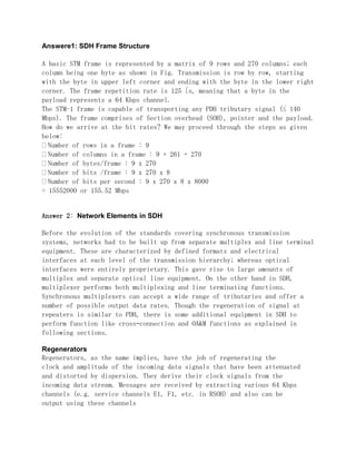
- 1. Answere1: SDH Frame Structure A basic STM frame is represented by a matrix of 9 rows and 270 columns; each column being one byte as shown in Fig. Transmission is row by row, starting with the byte in upper left corner and ending with the byte in the lower right corner. The frame repetition rate is 125 s, meaning that a byte in the payload represents a 64 Kbps channel. The STM-1 frame is capable of transporting any PDH tributary signal (≤ 140 Mbps). The frame comprises of Section overhead (SOH), pointer and the payload. How do we arrive at the bit rates? We may proceed through the steps as given below: Number of rows in a frame : 9 Number of columns in a frame : 9 + 261 = 270 Number of bytes/frame : 9 x 270 Number of bits /frame : 9 x 270 x 8 Number of bits per second : 9 x 270 x 8 x 8000 = 15552000 or 155.52 Mbps Answer 2: Network Elements in SDH Before the evolution of the standards covering synchronous transmission systems, networks had to be built up from separate multiplex and line terminal equipment. These are characterized by defined formats and electrical interfaces at each level of the transmission hierarchy; whereas optical interfaces were entirely proprietary. This gave rise to large amounts of multiplex and separate optical line equipment. On the other hand in SDH, multiplexer performs both multiplexing and line terminating functions. Synchronous multiplexers can accept a wide range of tributaries and offer a number of possible output data rates. Though the regeneration of signal at repeaters is similar to PDH, there is some additional equipment in SDH to perform function like cross–connection and OA&M functions as explained in following sections. Regenerators Regenerators, as the name implies, have the job of regenerating the clock and amplitude of the incoming data signals that have been attenuated and distorted by dispersion. They derive their clock signals from the incoming data stream. Messages are received by extracting various 64 Kbps channels (e.g. service channels E1, F1, etc. in RSOH) and also can be output using these channels
- 2. SDH Multiplexing A procedure by which multiple lower order path layer signals are adapted into a higher order path or the multiple higher order path layer signals are adapted into a multiplex section. Answer 3: VC(virtual container): container + POH TUG(tributary unit group): group of TU TU(tributary unit): VC + TU pointer AUG(administrative unit group):group of AU AU(administrative unit):TUG + AU pointer POH: pay load container Answer 5: Synchronization Methods The Synchronization Equipment Clock (SEC) generates the System Clock (T0) which is used for synchronization in internal processing and for all out going SDH signals and resynchronized. E12 (tributary) outputs (as stated earlier when E12 Resync optional feature is used). The SEC uses one of the four sources mentioned below as references to generate the T0. Two STM–1 inputs (This reference is known as T1 Ref.). Any two 2 Mbps inputs (T2 Ref.) Two External 2 Mbps Ref. (T3 Ref.) Internal Oscillator The system also outputs two reference clocks (T4) for use, if required, for use in other systems in the same place etc. they can be individually be Derived from The two STM-1 inputs T0 Different Modes of Synchronization a) Locked Mode: In this mode, the T0 is kept locked to the selected reference. If the selected reference is one of the STM–1 inputs, the Synchronization Status Message (SSM) on this input is transmitted in all the other outputs (in the S1 byte of the SOH) except in the return direction of this input. Instead, in this direction a ‘Do Not Use For Sync.’ message is inserted. That is, if the equipment at
- 3. Station A is taking the STM–1 input coming in from Station B as a reference, in the S1 byte (bit 5 to 8) of SOH a code which mean ‘Do Not Use Sync.’ is sent. This is to prevent the station B from using a derivative of its own clock (after a transmission delay) as reference for its clock. If used this may lead to the SEC of Stn. B perennially trying to get phase locked to the reference offered to it (This problem is referred to as a Timing Loop). The SSM otherwise indicates the quality level of the clock used through standard codes. When the system is operating in this mode, the difference of T0 and the internal clock of the system is calculated and stored as the ‘Hold over Value’ for use in the hold over mode. b) Hold Over Mode: When all the selected references for deriving T0 is lost, the system uses the Hold over Value’ stored in memory to continue to operate retaining the frequency it had when it was in the locked mode. Usually the system can work for more than 24 hours in this mode. c) Free Running Mode: When both the modes above are not operable, i.e., when no reference source was ever selected or a reference was lost before a hold over value was stored in memory etc., the system enters free running mode in which the internal timing reference is used.