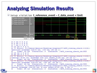
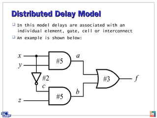
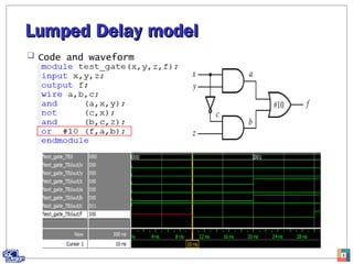
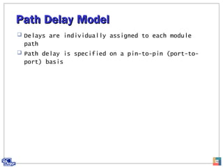
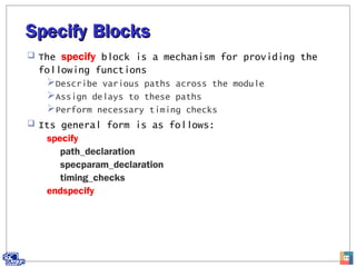
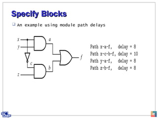
Hanbat
Hanbat
National
National
University
University
Advanced ModelingAdvanced Modeling
TechniquesTechniques
Gookyi Dennis N. A.Gookyi Dennis N. A.
SoC Design Lab.SoC Design Lab.
July.15.2014
ContentsContents
 Delay Modules
 Timing Checks
2
Delay ModelsDelay Models
 There are three delay models that are often used to
model various delays hardware module:
Distributed delay model
Lumped delay model
Path delay model
3
Distributed Delay ModelDistributed Delay Model
 In this model delays are associated with an
individual element, gate, cell or interconnect
 An example is shown below:
4
Distributed Delay ModelDistributed Delay Model
 Code and waveform
5
Distributed Delay ModelDistributed Delay Model
 RTL schematic
6
Lumped Delay modelLumped Delay model
 Delays are associated with the entire module
 The cumulative delay of all paths are lumped at the
single output
 An example is shown below:
7
Lumped Delay modelLumped Delay model
 Code and waveform
8
Lumped Delay modelLumped Delay model
 RTL schematic
9
Path Delay ModelPath Delay Model
 Delays are individually assigned to each module
path
 Path delay is specified on a pin-to-pin (port-to-
port) basis
10
Specify BlocksSpecify Blocks
 The specify block is a mechanism for providing the
following functions
Describe various paths across the module
Assign delays to these paths
Perform necessary timing checks
 Its general form is as follows:
specify
path_declaration
specparam_declaration
timing_checks
endspecify
11
Specify BlocksSpecify Blocks
 An example using module path delays
12
Specify BlocksSpecify Blocks
 Code and waveform
13
Path DeclarationPath Declaration
 There are three kinds of path declarations that can
be declared within a specify:
Simple path
Edge-sensitive path
State-dependent path
14
Simple PathSimple Path
 It simply construct a path from a path source to a
path destination
 It can be declared in one of the following forms:
Parallel connection
Full connection
15
Parallel ConnectionParallel Connection
 It uses the symbol => and every path source
connects to exactly one path destination
 It has the following form:
source => destination = delay_value;
16
Full ConnectionFull Connection
 Uses the symbol *> and every path source connects
to all path destination
 Its syntax is as follows:
source *> destination =delay_value
17
Full ConnectionFull Connection
 Code and waveform
18
State Dependent PathState Dependent Path
 In actual hardware module, the module path delays
might be changed when the states of input signals
to the circuit changes
 The module path delay can be assigned
conditionally, based on the value of the signals in
the circuit
 The general form is as follows:
if (cond_expr) simple_path_declaration
if (cond_expr) edge_sensitive_path_declaration
ifnone simple_path_declaration
19
State Dependent PathState Dependent Path
 The timing of NOR gate
20
State Dependent PathState Dependent Path
21
 Testbench and waveform
Specparam DeclarationSpecparam Declaration
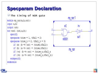
 It is used to define specify parameters which are
intended to provide timing and delay
 It has the general form as below:
specparam [range] specparam_assignment;
22
Specparam DeclarationSpecparam Declaration
 The timing of NOR gate
23
Specparam DeclarationSpecparam Declaration
 Waveform
24
Timing ChecksTiming Checks
 In Verilog, a set of functions is provided for
timing checks
 All checks must be inside the specify blocks
 The most commonly used timing checks include:
$setup
$hold
$setuphold
$width
$skew
$period
$recovery
25
Setup time checkSetup time check
 Setup time is the amount of time that data must be
stable before they are sampled
 The general form is as follows:
$setup (data_event, reference_event, limit);
 Violation is reported when:
t_reference_event – t_data_event < limit
 An example is shown below:
specify
$setup (data, posedge clock, 3);
endspecify
26
Hold Time CheckHold Time Check
 It is the amount of time that data must continually
remain stable after they have been sampled
 It has the general form as below:
$hold (reference_event, data_event, limit)
 Violation is reported when:
t_data_event – t_reference_event < limit
 An example is shown below:
specify
$hold (posedge clock, data, 3);
endspecify
27
Pulse Width CheckPulse Width Check
 Checks to see whether the width of a pulse meets
the minimum width requirement
 It has the following form:
$width (reference_event, limit);
 Violation is reported when:
t_data_event – t_reference_event < limit
 An example is shown below:
specify
$width (posedge reset, 10);
endspecify
28
Period CheckPeriod Check
 This is used to check whether the period of a
signal meets the minimum period requirement
 It has the general form as below:
$period (reference_event, limit);
 Violation is reported when:
t_data_event – t_reference_event < limit
 An example is shown below:
specify
$period (posedge clk, 25)
endspecify
29
Timing ChecksTiming Checks
 An example is a d-ff with timing checks
 The simulator will report errors when the timing
relationship between the inputs clk, d and reset_n
violates any specification on the timing checks:
$setup, $hold, $period
30
Timing ChecksTiming Checks
 Code
31
Timing ChecksTiming Checks
 Testbench
32
Timing ChecksTiming Checks
 Simulation results
33
Analyzing Simulation ResultsAnalyzing Simulation Results
 From 0 to 10 time units, there are no violations
34
Analyzing Simulation ResultsAnalyzing Simulation Results
 After 10ns, the period is violated t_data – t_reference <
limit
35
Analyzing Simulation ResultsAnalyzing Simulation Results
 After 20ns, there are three violations
Setup
Period
Hold
36
Analyzing Simulation ResultsAnalyzing Simulation Results
 Setup violation t_reference_event – t_data_event < limit
37
Analyzing Simulation ResultsAnalyzing Simulation Results
 Period violation t_data – t_reference < limit
38
Analyzing Simulation ResultsAnalyzing Simulation Results
 Hold violation t_data_event – t_reference_event < limit
39

Advanced modeling techniques