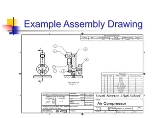
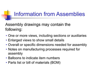
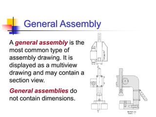
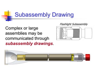
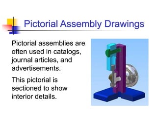
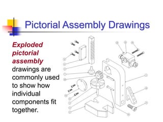
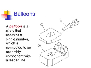
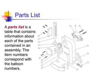
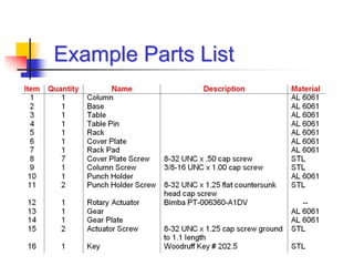
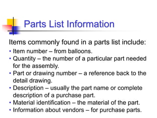
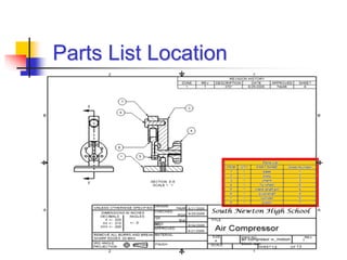
Assembly Drawings,
Balloons,
and
Parts Lists
A design that has been approved for prototype or
full-scale manufacture requires a set of working
drawings to communicate the object’s geometry to
everyone involved with its manufacture and
assembly.
Working drawings are a complete set of
documents that include:
Working Drawings
• Individual part drawings
• One or more assembly
drawings
• A parts list
Assembly Drawings
An assembly drawing shows how all of the
parts of a multi-component design fit together,
and are generally depicted as one or more
orthographic projections.
One or more full section views are often used
in an assembly drawing to show necessary
internal features.
Example Assembly Drawing
Information from Assemblies
• One or more views, including sections or auxiliaries
• Enlarged views to show small details
• Overall or specific dimensions needed for assembly
• Notes on manufacturing processes required for
assembly
• Balloons to indicate item numbers
• Parts list or bill of materials (BOM)
Assembly drawings may contain the
following:
• Design Assembly
• General Assembly
• Detail Assembly
• Erection Assembly
• Subassembly
• Pictorial Assembly
Types of Assembly Drawings
Design assemblies are used to
show various relationships
between components.
The design assembly at the right
shows the kinematic relationship
that exists between the fly
wheel’s 360° rotation, and the
extreme angular motion of the
piston cylinder body.
Design Assembly
Design assemblies are often made from sketches
during the preliminary phases of a design process
to study the relationships that exist between the
components before the design is modeled.
Design Assembly
A general assembly is the
most common type of
assembly drawing. It is
displayed as a multiview
drawing and may contain a
section view.
General assemblies do
not contain dimensions.
General Assembly
Detail Assembly
A detail assembly is a combination of an
assembly view with several of its parts
depicted as dimensioned multiview drawings
on one drawing sheet.
This practice, though not common, reduces
the number of drawing sheets needed, and is
more appropriate for designs with small
numbers of components.
Example Detail Assembly
Erection Assembly
• Similar to general assemblies, except
dimensions and fabrication specifications are
commonly included.
• Typically associated with cabinetry or products
that are made from structural steel.
• Used for both fabrication and assembly.
Subassembly Drawing
Complex or large
assemblies may be
communicated through
subassembly drawings.
Flashlight Subassembly
Pictorial Assembly
• Usually depicted as an
isometric or perspective
drawing.
• May be rendered to imitate
photographic quality.
• Uses include:
- Sales promotion
- Customer self-assembly
- Maintenance procedures
Pictorial assemblies are
often used in catalogs,
journal articles, and
advertisements.
This pictorial is
sectioned to show
interior details.
Pictorial Assembly Drawings
Exploded
pictorial
assembly
drawings are
commonly used
to show how
individual
components fit
together.
Pictorial Assembly Drawings
Balloons
A balloon is a
circle that
contains a
single number,
which is
connected to an
assembly
component with
a leader line.
• All balloons on a drawing should be the same
size.
• Balloons should be grouped together in an easy-
to-read pattern.
• Balloon numbers must correspond to item
numbers in a parts list.
• Balloons should not have horizontal or vertical
leader lines.
Balloon Guidelines
A parts list is a
table that contains
information about
each of the parts
contained in an
assembly. The
item numbers
correspond with
the balloon
numbers.
Parts List
Example Parts List
Parts List Information
• Item number – from balloons.
• Quantity – the number of a particular part needed
for the assembly.
• Part or drawing number – a reference back to the
detail drawing.
• Description – usually the part name or complete
description of a purchase part.
• Material identification – the material of the part.
• Information about vendors – for purchase parts.
Items commonly found in a parts list include:
Parts List Location
• Above the title block – most common
• Upper right corner
• Upper left corner
• A convenient location on the drawing
The location of a parts list usually depends on
company standards. Common locations
include:
Parts List Location

Assembly_Drawings_Balloons_Parts_Lists.ppt

  • 1.
  • 2.
    A design thathas been approved for prototype or full-scale manufacture requires a set of working drawings to communicate the object’s geometry to everyone involved with its manufacture and assembly. Working drawings are a complete set of documents that include: Working Drawings • Individual part drawings • One or more assembly drawings • A parts list
  • 3.
    Assembly Drawings An assemblydrawing shows how all of the parts of a multi-component design fit together, and are generally depicted as one or more orthographic projections. One or more full section views are often used in an assembly drawing to show necessary internal features.
  • 4.
  • 5.
    Information from Assemblies •One or more views, including sections or auxiliaries • Enlarged views to show small details • Overall or specific dimensions needed for assembly • Notes on manufacturing processes required for assembly • Balloons to indicate item numbers • Parts list or bill of materials (BOM) Assembly drawings may contain the following:
  • 6.
    • Design Assembly •General Assembly • Detail Assembly • Erection Assembly • Subassembly • Pictorial Assembly Types of Assembly Drawings
  • 7.
    Design assemblies areused to show various relationships between components. The design assembly at the right shows the kinematic relationship that exists between the fly wheel’s 360° rotation, and the extreme angular motion of the piston cylinder body. Design Assembly
  • 8.
    Design assemblies areoften made from sketches during the preliminary phases of a design process to study the relationships that exist between the components before the design is modeled. Design Assembly
  • 9.
    A general assemblyis the most common type of assembly drawing. It is displayed as a multiview drawing and may contain a section view. General assemblies do not contain dimensions. General Assembly
  • 10.
    Detail Assembly A detailassembly is a combination of an assembly view with several of its parts depicted as dimensioned multiview drawings on one drawing sheet. This practice, though not common, reduces the number of drawing sheets needed, and is more appropriate for designs with small numbers of components.
  • 11.
  • 12.
    Erection Assembly • Similarto general assemblies, except dimensions and fabrication specifications are commonly included. • Typically associated with cabinetry or products that are made from structural steel. • Used for both fabrication and assembly.
  • 13.
    Subassembly Drawing Complex orlarge assemblies may be communicated through subassembly drawings. Flashlight Subassembly
  • 14.
    Pictorial Assembly • Usuallydepicted as an isometric or perspective drawing. • May be rendered to imitate photographic quality. • Uses include: - Sales promotion - Customer self-assembly - Maintenance procedures
  • 15.
    Pictorial assemblies are oftenused in catalogs, journal articles, and advertisements. This pictorial is sectioned to show interior details. Pictorial Assembly Drawings
  • 16.
    Exploded pictorial assembly drawings are commonly used toshow how individual components fit together. Pictorial Assembly Drawings
  • 17.
    Balloons A balloon isa circle that contains a single number, which is connected to an assembly component with a leader line.
  • 18.
    • All balloonson a drawing should be the same size. • Balloons should be grouped together in an easy- to-read pattern. • Balloon numbers must correspond to item numbers in a parts list. • Balloons should not have horizontal or vertical leader lines. Balloon Guidelines
  • 19.
    A parts listis a table that contains information about each of the parts contained in an assembly. The item numbers correspond with the balloon numbers. Parts List
  • 20.
  • 21.
    Parts List Information •Item number – from balloons. • Quantity – the number of a particular part needed for the assembly. • Part or drawing number – a reference back to the detail drawing. • Description – usually the part name or complete description of a purchase part. • Material identification – the material of the part. • Information about vendors – for purchase parts. Items commonly found in a parts list include:
  • 22.
    Parts List Location •Above the title block – most common • Upper right corner • Upper left corner • A convenient location on the drawing The location of a parts list usually depends on company standards. Common locations include:
  • 23.

Editor's Notes

  • #7 Project Lead The Way, Inc. Copyright 2007
  • #11 Project Lead The Way, Inc. Copyright 2007
  • #12 Project Lead The Way, Inc. Copyright 2007