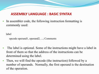
This document discusses assembly language basics including instruction syntax, operands, constants, comments, and data definition directives. It also covers the unified assembly language (UAL) used for ARM and Thumb instructions, which allows selection of 16-bit and 32-bit instructions using the same syntax. Suffixes can specify instruction width, and 32-bit Thumb-2 instructions can be half word aligned.
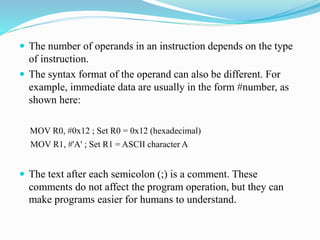
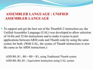
![ We can define constants using EQU, and then use them inside your
program code. For example,
NVIC_IRQ_SETEN0 EQU 0xE000E100
NVIC_IRQ0_ENABLE EQU 0x1
...
LDR R0,=NVIC_IRQ_SETEN0; ; LDR here is a pseudo-instruction that
; convert to a PC relative load by
; assembler.
MOV R1,#NVIC_IRQ0_ENABLE ; Move immediate data to register
STR R1,[R0] ; Enable IRQ 0 by writing R1 to address
; in R0
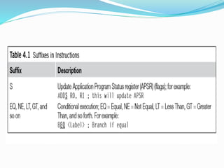
A number of data definition directives are available for insertion of
constants inside assembly code.
For example, DCI (Define Constant Instruction) can be used to code
an instruction if your assembler cannot generate the exact instruction
that we want and if we know the binary code for the instruction.
DCI 0xBE00 ; Breakpoint (BKPT 0), a 16-bit instruction](https://image.slidesharecdn.com/assemblybasics-210829090616/85/Assembly-basics-4-320.jpg)
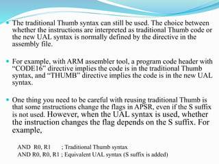
![ We can use DCB (Define Constant Byte) for byte size constant values,
such as characters, and Define Constant Data (DCD) for word size
constant values to define binary data in your code.
LDR R3,=MY_NUMBER ; Get the memory address value of MY_NUMBER
LDR R4,[R3] ; Get the value code 0x12345678 in R4
...
LDR R0,=HELLO_TXT ; Get the starting memory address of
; HELLO_TXT
BL PrintText ; Call a function called PrintText to
; display string
...
MY_NUMBER
DCD 0x12345678
HELLO_TXT
DCB "Hellon",0 ; null terminated string](https://image.slidesharecdn.com/assemblybasics-210829090616/85/Assembly-basics-5-320.jpg)

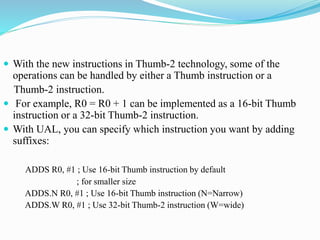

![ The 32-bit Thumb-2 instructions can be half word aligned. For
example, you can have a 32-bit instruction located in a half word
location.
0x1000 : LDR r0,[r1] ;a 16-bit instructions (occupy 0x10000x1001)
0x1002 : RBIT.W r0 ;a 32-bit Thumb-2 instruction (occupy
; 0x1002-0x1005)
Most of the 16-bit instructions can only access registers R0–R7;
32-bit Thumb-2 instructions do not have this limitation.
However, use of PC (R15) might not be allowed in some of the
instructions. Refer to the ARM v7-M Architecture Application
Level Reference Manual [Ref. 2] (section A4.6) if you need to
find out more detail in this area.](https://image.slidesharecdn.com/assemblybasics-210829090616/85/Assembly-basics-12-320.jpg)


![[ASM]Lab4](https://cdn.slidesharecdn.com/ss_thumbnails/asmlab4-151121101809-lva1-app6891-thumbnail.jpg?width=640&height=640&fit=bounds)


![Chap03[1]](https://cdn.slidesharecdn.com/ss_thumbnails/chap031-140914002717-phpapp01-thumbnail.jpg?width=640&height=640&fit=bounds)


