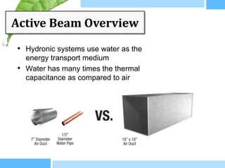
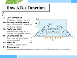
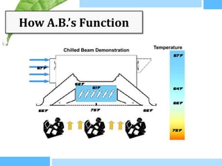
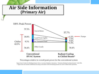
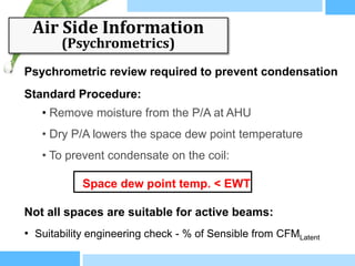
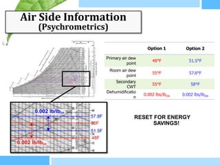
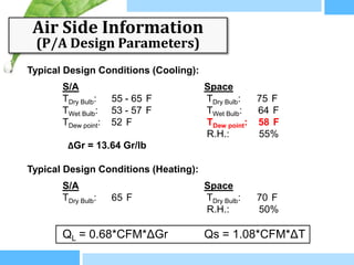
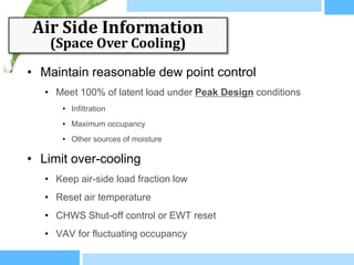
The document discusses active beam systems, including their origin, overview, function, construction, comparisons to other systems, air-side and water-side information, capacity, benefits, limitations, and applications. Active beams are a hydronic system that uses water to transport energy and induce room air through nozzles to provide heating or cooling. They can provide significant fan energy savings compared to all-air systems while maintaining thermal comfort. Proper design of the air-side and water-side is important to control humidity and achieve capacity.

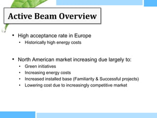
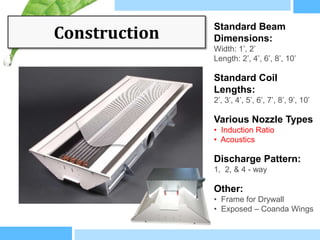


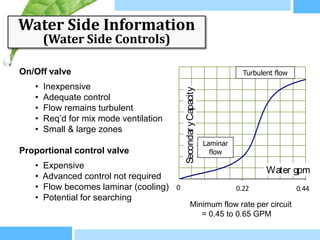
![Air Side Information
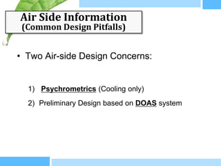
(Plenum Air Pressure Drop)
250
1.00”
230
0.93”
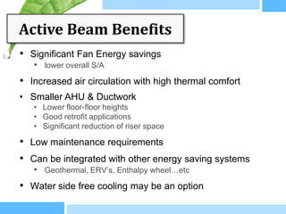
• Fan Static is higher
210 • Less penalty then high air flow
0.85”
Plenum Pressure [Pa]
190
• Can correlate pressure and air flow
0.77”
• Air volume is difficult to measure
170
0.69” K 60A
150
0.60” K 60C • Measuring pressure is easy and
130
0.52”
reliable
K 60D
110
0.44”
K 60B • Pressure is the common factor
90
0.36”
70
• Plenum and ducting should be
0.28” Primary air [l/s] sealed
50
0.20” 0 5 10 15 20 25 30 35 40
CFM 10 21 32 42 53 64 74 85](https://image.slidesharecdn.com/apr122012chilledbeampresentation-1336107535788-phpapp02-120504000356-phpapp02/85/Apr-12-2012-Chilled-Beam-Presentation-21-320.jpg)
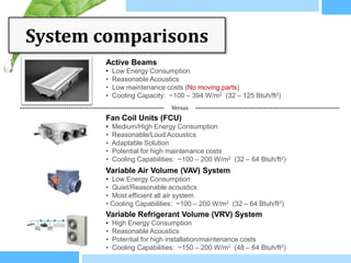
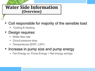
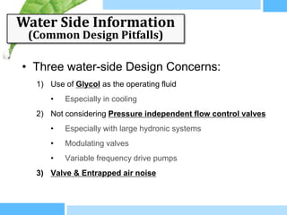
![Air Side Information
(Acoustics)
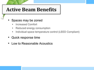
45
40
2’x8’ – Larger Nozzles Chart reports
35 acoustic values
LwA [dB(A)]
without room
30 attenuation
effect
25
2’x8’ – Smaller Nozzles Active beams can
20
be very quiet!
15
0.4 0.6 0.8 1 1.2 1.4
Plenum Pressure [“w.c.]](https://image.slidesharecdn.com/apr122012chilledbeampresentation-1336107535788-phpapp02-120504000356-phpapp02/85/Apr-12-2012-Chilled-Beam-Presentation-22-320.jpg)
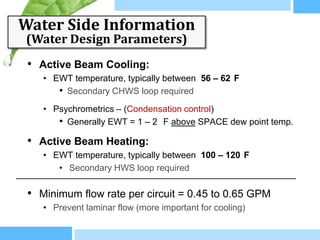
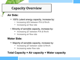
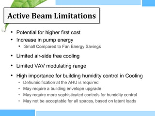
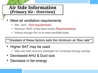
![Capacity vs. Air Volume
40
A-DT 8
A-DT 10
35
B-DT 8
B-DT 10 • Increasing air flow rate and
C-DT 8
30
C-DT 10
D-DT 8
pressure:
D-DT 10
Air Volume [l/s]
• Significant Increase in Capacity
25
20 • Increasing GPM in turbulent
flow:
15
• Marginal Increase in Capacity
10
Secondary Capacity [W]
5
100 200 300 400 500 600 700 800
Typical sensible range is approx. 250 – 1500 BTUh/Ft](https://image.slidesharecdn.com/apr122012chilledbeampresentation-1336107535788-phpapp02-120504000356-phpapp02/85/Apr-12-2012-Chilled-Beam-Presentation-36-320.jpg)