Downloaded 340 times


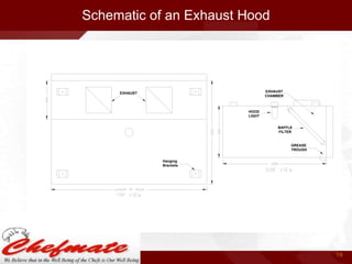
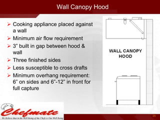
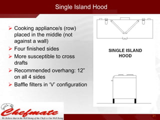
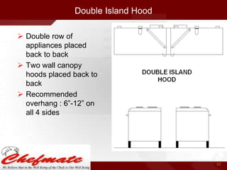

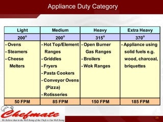
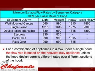


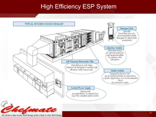
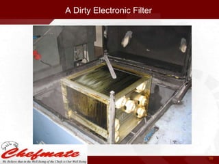
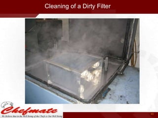
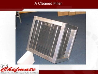


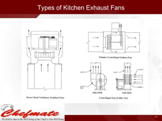


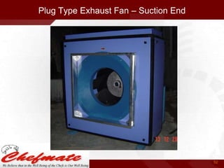

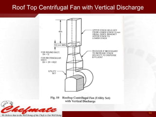

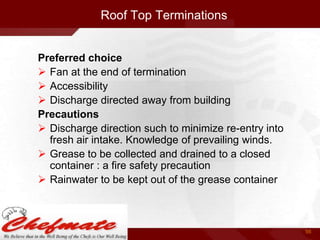


This document provides information about kitchen ventilation systems. It discusses the types of buildings that require kitchen ventilation such as hotels, restaurants, hospitals, etc. It covers the design of kitchen ventilation systems including components like exhaust hoods, exhaust fans, ductwork, filters and makeup air systems. The document provides guidelines for calculating exhaust air flow rates based on the type of cooking equipment. It also discusses best practices for installation and maintenance of kitchen ventilation systems for effective capture and removal of heat, effluents and grease from commercial kitchens.


