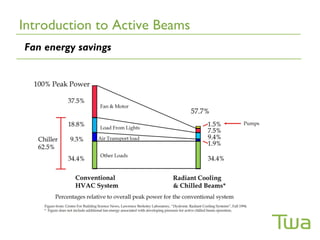
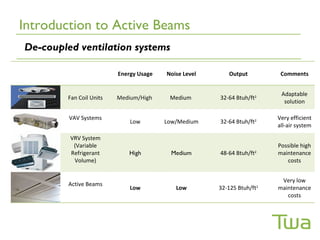
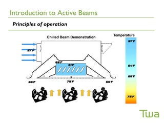
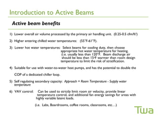
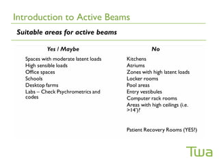
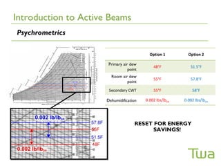
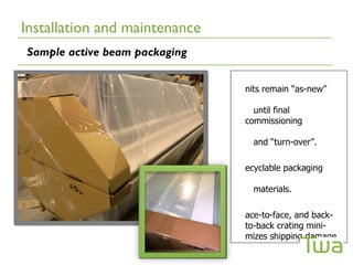
OPERATION & COMMISSIONING OF
        ACTIVE BEAMS


                 Twa Panel Systems Inc.
                 1201 – 4th Street
                 Nisku, AB
                 Canada, T9E 7L3
                 (780)-955-8757

                 www.twapanels.ca
Agenda
Agenda
Introduction to Active (Chilled) Beams
Introduction to Active Beams
Fan energy savings
Introduction to Active Beams
De-coupled ventilation systems

                         Energy Usage   Noise Level      Output         Comments


                                                                        Adaptable
        Fan Coil Units   Medium/High     Medium       32-64 Btuh/ft2
                                                                         solution

         VAV Systems                                                   Very efficient
                             Low        Low/Medium    32-64 Btuh/ft2
                                                                       all-air system

         VRV System
          (Variable                                                    Possible high
         Refrigerant        High          Medium      48-64 Btuh/ft2   maintenance
          Volume)                                                         costs


                                                                        Very low
         Active Beams
                             Low           Low        32-125 Btuh/ft
                                                                   2
                                                                       maintenance
                                                                          costs
Introduction to Active Beams
Principles of operation
Introduction to Active Beams
 Active beam benefits
1) Lower overall air volume processed by the primary air handling unit. (0.25-0.5 cfm/ft2)
2) Higher entering chilled water temperatures: (55°F-61°F).
3) Lower hot water temperatures: Select beams for cooling duty, then choose
                                appropriate hot water temperature for heating.
                                 (i.e. usually less than 120°F. Beam discharge air
                                 should be less than 15oF warmer than room design
                                temperature to limit the risk of stratification.
4) Suitable for use with water-to-water heat pumps, and has the potential to double the
   COP of a dedicated chiller loop.
5) Self regulating secondary capacity: Approach = Room Temperature - Supply water
   temperature
6) VAV control:     Can be used to strictly limit room air velocity, provide linear
                   temperature control, and additional fan energy savings for areas with
                  highly variable latent loads.
                  (i.e. Labs, Boardrooms, coffee rooms, classrooms, etc…)
Introduction to Active Beams
Suitable areas for active beams
Introduction to Active Beams
Psychrometrics

                                            Option 1         Option 2

                       Primary air dew
                                              48°F            51.5°F
                                  point
                        Room air dew
                                              55°F            57.8°F
                                point

                       Secondary CWT          55°F             58°F

                      Dehumidification    0.002 lbs/lbDA   0.002 lbs/lbDA


                                     RESET FOR ENERGY
                                           SAVINGS!
Introduction to Active Beams
 Condensation risks
Areas of greatest condensation risk:
1) Near points of entry to the building
4)At the perimeter, with mixed-mode ventilation
5)Structures with poor building envelopes, including retrofit applications
6)In areas with highly variable latent loads:
      • Board rooms
      • Lunch / coffee rooms
      • Etc…
Condensation prevention strategies may include:
10)De-activation of secondary chilled water supply, by zone, via loss of dew-point from
    sensors mounted to CWS lines. (… or via combination: DB / RH zone stats, or
other…)
2) Tempering secondary chilled water supply by zone via:
     • Three-way mixing valve
     • Injection pumps
3) Etc…
Introduction to Active Beams
DOAS Information Resource

1) http://doas.psu.edu/

2) Not all primary air handling systems are DOAS!
Introduction to Active Beams
Placement within the ceiling


                               P2 drops rapidly
                               moving into the
                               room

                               P3 = ½ at 3ft into
                               occupied zone
Introduction to Active Beams
Inherent comfort with active beams


       Active Beam


                         Diffuser
Introduction to Active Beams
Beam acoustics


                                Chart reports
                               acoustic values
                                without room
                                 attenuation
                                    effect


                               Active beams can
                                 be very quiet!
Introduction to Active Beams
1/3rd Octave band analysis

                             Owens Corning Acoustic Testing
                             •Acoustic test standards may include:
                                    ISO3741
                                    ASHRAE Std. 70

                             • Reverberant chamber (No Attenuation)

                             Manufacturer A = Worst Case
                             •   2’ x 8’ – D nozzle @ 1.20”w.c.
                             •   Peak in the 2.5 KHz Band
                             •   Lw (dB) = 39.1
                             •   LwA (dBA) = 38.8
                             •   NC = 24 !
Installation and maintenance
Fastening beams to the structure


                                                    Upstream damper
                                                    at SMACNA
                                                    recommended
                                                    minimum distance

                                                          Drywall


                       N.B. - Include seismic restraint
                       where required by code
Installation and maintenance
T-bar mounting detail


       Width                   Length
Installation and maintenance
Exposed / pendant type units


                               Coanda wings
                               required for
                               proper throw
                               characteristics
Installation and maintenance
Installation “Tips”

1. “Rough-in”: piping, ducting, concrete threaded inserts, and beams, prior
   to T-bar installation. Lower beams into T-bar for final positioning.

3. Store beams on-site indoors whenever possible, in a low traffic area, and
   otherwise covered for protection from the elements.

5. Leave plastic film on each unit to minimize site damage, and prevent coil
   / unit fouling.

7. Match beam label to schedule; - beams look alike! Confirm that the right
   beam is in the right room. Contractor suggestion: - Confirm packing slip
   matches shop drawing requirements upon receipt of material.

9. Limit flexible duct to no more than 10’. Avoid sharp turns in ductwork.
Installation and maintenance
Installation “Tips”

1. Plan for access doors, and possibly welded-aluminum frames, with beams
   mounted in dry-wall ceilings.

3. Manage glazing surface temperatures by planning discharge
   configuration. With high quality glass, beams which discharge
   perpendicular to the glazing, are typically preferred.

5. Stainless steel flexible hoses allow for some adjustment within the ceiling
   grid.
Installation and maintenance
Sample active beam packaging


                               nits remain “as-new”

                                 until final
                               commissioning

                                 and “turn-over”.

                               ecyclable packaging

                                 materials.

                               ace-to-face, and back-
                               to-back crating mini-
                               mizes shipping damage.
Installation and maintenance
Beams mounted with aircraft cable


                                    Note protective
                                    film at inlet of
                                    unit mounted coil
Installation and maintenance
     IOM and precautions


  ead the manufacturer’s Installation Operation and Maintenance Manual

  ay particular note of any precautions which have been identified as high
  risk conditions. (i.e. minimum two people to handle beams 6’ and larger,
  pulling on un-latched door may cause hardware failure, be cautious of
  sharp edges, limit flex duct connections to 10’ maximum, etc…)

  o NOT circulate water through the beam mounted coil until the “mains”
  have been properly “de-greased” / flushed.

  o NOT remove protective plastic film from beam body until the space has
  been appropriately cleaned, to minimize fouling of the coil

  O lower the secondary chilled water temperature slowly to limit the risk of
  condensation damage during start-up.
Installation and maintenance
Coil maintenance


  ctive beams require practically no maintenance. If the coil remains dry, as
  expected, there is very little risk of fin “bridging”.


  ecommended cleaning schedules typically involve lowering, or removing
  the perforated doors / panels, in front of unit mounted coil, at 6-Months,
  and 1-Yr., to establish a maintenance schedule. Areas with higher airborne
  contamination require more frequent cleaning.


  ften, cleaning schedules can extend to between 3-5 years in spaces subject
  to weekly housekeeping.


  igher housekeeping frequency, reduces the intervals between coil
Installation and maintenance
Coil maintenance


  Vacuum with or
  without a “horse-
  hair” bristle brush
Installation and maintenance
Unit cleanliness prior to start-up


  eave active beams wrapped to prevent fouling unit or coil.


  ipe unit with a damp rag to remove surface dirt, or vacuum with a horse-
  hair bristle brush.


  o NOT scrub the paint. Damage to the finish may occur.


   soft bristle brush and mild detergent with water, can be used to remove
  stubborn “smudging”, if required.


  eams ship with repair kits for surface scratched units. Do NOT spray the
  unit directly with “spray-bomb” type matched paint. Use artist paint
Air-side control and measurement
 Ducting for equal static pressure

                              Pt = Ps + Pv
Pt = total pressure (”w.c.)
Ps = static pressure (”w.c.)
Pv = velocity pressure (”w.c.)
If velocity pressure is kept negligibly low, then the same static pressure will
hold throughout the duct. ( i.e. Only if transport loss can be neglected).

                          Pv = 0,5 x r x v2
Pv = velocity pressure (”w.c.)
r = air density (0.075 lbs/ft3)
v2 = air velocity (fpm)
   At < (590 fpm) duct air velocity Pv < (0.02”w.c.)
   At < (590 fpm) transport
   Ø = (5”) < (0.001”w.c/ft.)
   Ø = (8”) < (.0007”w.c./ft.)
Low air volumes required for beams makes using round ducting practical
and low air velocity achievable.
Air-side control and measurement
Vary primary air pressure for capacity control ?


                                       AV primary air flow is

                                         typically simple with


                                       arying the plenum pressure
                                         orifice plate “Iris” type
                                       yields a non-linear capacity
                                       response. Tight control
                                       with variable plenum
                                         dampers.
                                       pressure is typically
                                       impractical.
Air-side control and measurement
Vary primary air pressure for capacity control ?
Air-side control and measurement
 Recommended CAV damper types

        Iris Dampers –
   (angled multi-leaf blades)


Pressure independent –
butterfly type


                                   Iris Dampers
Air-side control and measurement
Damper “Tips”


  ize dampers for flow and pressure drop.
    • i.e. Do NOT oversize the damper by simply installing a nominal duct
      diameter damper. Check range of flow control, step-down if required.


  enturi – style dampers are typically only used with labs, and narrow-band
  pressurization control.


  heck for flow generated noise with larger pressure drops.
   • Add duct silencers if necessary.


  onsider VAV air valves for spaces with highly variable latent loads.
   • Be aware of additional control requirements
   • Consider “occupancy” type (i.e. 2-position) air valves for these spaces
      in an effort to manage control costs.
Air-side control and measurement
Acoustics


  atch for flow generated noise across Iris damper.


  dd duct mounted silencers if required.
Air-side control and measurement
Balancing and confirmation


  eams are considered a constant volume device. Apply a known plenum
  static pressure, and the cross-sectional area of each nozzle sums to yield
  the total primary air delivered by the beam. Adjust orifice ∆P for beams
  of common pressure; - their nozzle determines the primary air flow rate.


  ince the induction ratio is exceedingly difficult to field measure, the most
  accurate means of determining the primary air delivery, is to rely on the
  manufacturer’s plenum pressure vs. volume relationship, which is typically
  measured with a precision orifice. Confirmation of zone flow rates can be
  accomplished via a duct traverse at a node of common intersection.


  low hoods cannot be used to determine total air flow into the space due
  to the recirculation component of the room air.
Air-side control and measurement
Challenges


  ominal duct size vs. ∆P across Iris dampers.


  oning to minimize capital costs.


  ight-time set-back.


  imultaneous perimeter heating with core cooling.


  ir-side free-cooling.


  ew-point control.
Water-side control and measurement
Self-regulating thermal capacity

                                        Example 1
                          (1365 Btuh)   Room Temp       = 75oF
                                        Water temp      = 61oF
                                        Approach temp = 75oF-61oF
                                                        = 14oF
                                               Capacity = X
                           (682 Btuh)
                                        Room Temp      = 68oF
                                        Water Temp     = 61oF
                                        Approach temp = 68oF-61oF
                                                       = 7oF
                                              Capacity = 1/2X
Water-side control and measurement
Modulating water flow


             Turbulent
               flow


       Laminar
         flow


Single circuit water flow   Temperature controlled water
•Non-linear                 •Restricted to zone control
•Expensive                  •Expensive
•Maintenance issues?        •Maintenance issues?
Water-side control and measurement
Challenges


  ater-side free cooling


  oning


  hilled water reset by zone


  alve authority
     (Ensure that the control valves are sized based on Cv, NOT
       line size)
Water-side control and measurement
“Tips” for easier commissioning


 se pressure independent flow regulating valves


 everse-return piping can sometimes make life “easier” in each zone


 pply venting “liberally”


                                 ressure independent
                                 water control valve

                                   (Constant Flow
                                 Rate)
Start-up
Start-up
Sample start-up sequence


  onfirm start-up and operating sequence with the: plans, specifications, and
  consulting engineer.


  onfirm primary air ducting is free of dirt and debris to prevent beam nozzle
  clogging.


  eal all duct leaks, and ensure all duct access ports are affixed to the duct to
  achieve specified duct leakage rates.


  lit protective film at the active beam discharge to allow primary air to enter the
  space. Do NOT remove the protective film, until the work space is in an “as-
Start-up
Sample start-up sequence (cont’d)


  o NOT operate the active beams for temporary heat without prior written
  approval from the consulting engineer.


  lose all operable windows, and ensure building exit doors are sealed to assist in
  the envelope dehumidification.


  ommission and operate the primary air handling unit for building envelope
  dehumidification.


  alance supply air ducting to each zone.
Start-up
Sample start-up sequence (cont’d)


  nsure a clean environment within which the active beams will operate (i.e. no
  gypsum dust or other construction contamination)


  emove protective film from active beam units


  nsure piping “mains” have been flushed and “leak-tested”, prior to being
  connected to the beam coils


  O NOT UNDER ANY CIRCUMSTANCES FLUSH THE PIPING SYSTEM
  THROUGH THE BEAM MOUNTED COILS.
Start-up
Sample start-up sequence (cont’d)


  onfirm that all air has been removed from the distribution piping. Deliver excess
  water by increasing the pump flow, or by closing other zones to assist in the
  removal of air from the system.


  nce the building envelope dew point has been reached, slowly lower the
  secondary chilled water temperature to the scheduled design value. Note that
  dehumidifying the building envelope may require several days, or up to a week
  initially, to completely dehumidify the space.


  onfirm secondary water conditions regularly to ensure that it is properly filtered,
  and appropriately inhibited.
Start-up
Shop drawings and schedules as a tool for commissioning
Sample space serviced by active beams
Child care classroom, California

Active Beam Commissioning Overview

  • 1.
    OPERATION & COMMISSIONINGOF ACTIVE BEAMS Twa Panel Systems Inc. 1201 – 4th Street Nisku, AB Canada, T9E 7L3 (780)-955-8757 www.twapanels.ca
  • 2.
  • 3.
  • 4.
    Introduction to Active(Chilled) Beams
  • 5.
    Introduction to ActiveBeams Fan energy savings
  • 6.
    Introduction to ActiveBeams De-coupled ventilation systems Energy Usage Noise Level Output Comments Adaptable Fan Coil Units Medium/High Medium 32-64 Btuh/ft2 solution VAV Systems Very efficient Low Low/Medium 32-64 Btuh/ft2 all-air system VRV System (Variable Possible high Refrigerant High Medium 48-64 Btuh/ft2 maintenance Volume) costs Very low Active Beams Low Low 32-125 Btuh/ft 2 maintenance costs
  • 7.
    Introduction to ActiveBeams Principles of operation
  • 8.
    Introduction to ActiveBeams Active beam benefits 1) Lower overall air volume processed by the primary air handling unit. (0.25-0.5 cfm/ft2) 2) Higher entering chilled water temperatures: (55°F-61°F). 3) Lower hot water temperatures: Select beams for cooling duty, then choose appropriate hot water temperature for heating. (i.e. usually less than 120°F. Beam discharge air should be less than 15oF warmer than room design temperature to limit the risk of stratification. 4) Suitable for use with water-to-water heat pumps, and has the potential to double the COP of a dedicated chiller loop. 5) Self regulating secondary capacity: Approach = Room Temperature - Supply water temperature 6) VAV control: Can be used to strictly limit room air velocity, provide linear temperature control, and additional fan energy savings for areas with highly variable latent loads. (i.e. Labs, Boardrooms, coffee rooms, classrooms, etc…)
  • 9.
    Introduction to ActiveBeams Suitable areas for active beams
  • 10.
    Introduction to ActiveBeams Psychrometrics Option 1 Option 2 Primary air dew 48°F 51.5°F point Room air dew 55°F 57.8°F point Secondary CWT 55°F 58°F Dehumidification 0.002 lbs/lbDA 0.002 lbs/lbDA RESET FOR ENERGY SAVINGS!
  • 11.
    Introduction to ActiveBeams Condensation risks Areas of greatest condensation risk: 1) Near points of entry to the building 4)At the perimeter, with mixed-mode ventilation 5)Structures with poor building envelopes, including retrofit applications 6)In areas with highly variable latent loads: • Board rooms • Lunch / coffee rooms • Etc… Condensation prevention strategies may include: 10)De-activation of secondary chilled water supply, by zone, via loss of dew-point from sensors mounted to CWS lines. (… or via combination: DB / RH zone stats, or other…) 2) Tempering secondary chilled water supply by zone via: • Three-way mixing valve • Injection pumps 3) Etc…
  • 12.
    Introduction to ActiveBeams DOAS Information Resource 1) http://doas.psu.edu/ 2) Not all primary air handling systems are DOAS!
  • 13.
    Introduction to ActiveBeams Placement within the ceiling P2 drops rapidly moving into the room P3 = ½ at 3ft into occupied zone
  • 14.
    Introduction to ActiveBeams Inherent comfort with active beams Active Beam Diffuser
  • 15.
    Introduction to ActiveBeams Beam acoustics Chart reports acoustic values without room attenuation effect Active beams can be very quiet!
  • 16.
    Introduction to ActiveBeams 1/3rd Octave band analysis Owens Corning Acoustic Testing •Acoustic test standards may include:  ISO3741  ASHRAE Std. 70 • Reverberant chamber (No Attenuation) Manufacturer A = Worst Case • 2’ x 8’ – D nozzle @ 1.20”w.c. • Peak in the 2.5 KHz Band • Lw (dB) = 39.1 • LwA (dBA) = 38.8 • NC = 24 !
  • 17.
  • 18.
    Installation and maintenance Fasteningbeams to the structure Upstream damper at SMACNA recommended minimum distance Drywall N.B. - Include seismic restraint where required by code
  • 19.
    Installation and maintenance T-barmounting detail Width Length
  • 20.
    Installation and maintenance Exposed/ pendant type units Coanda wings required for proper throw characteristics
  • 21.
    Installation and maintenance Installation“Tips” 1. “Rough-in”: piping, ducting, concrete threaded inserts, and beams, prior to T-bar installation. Lower beams into T-bar for final positioning. 3. Store beams on-site indoors whenever possible, in a low traffic area, and otherwise covered for protection from the elements. 5. Leave plastic film on each unit to minimize site damage, and prevent coil / unit fouling. 7. Match beam label to schedule; - beams look alike! Confirm that the right beam is in the right room. Contractor suggestion: - Confirm packing slip matches shop drawing requirements upon receipt of material. 9. Limit flexible duct to no more than 10’. Avoid sharp turns in ductwork.
  • 22.
    Installation and maintenance Installation“Tips” 1. Plan for access doors, and possibly welded-aluminum frames, with beams mounted in dry-wall ceilings. 3. Manage glazing surface temperatures by planning discharge configuration. With high quality glass, beams which discharge perpendicular to the glazing, are typically preferred. 5. Stainless steel flexible hoses allow for some adjustment within the ceiling grid.
  • 23.
    Installation and maintenance Sampleactive beam packaging nits remain “as-new” until final commissioning and “turn-over”. ecyclable packaging materials. ace-to-face, and back- to-back crating mini- mizes shipping damage.
  • 24.
    Installation and maintenance Beamsmounted with aircraft cable Note protective film at inlet of unit mounted coil
  • 25.
    Installation and maintenance IOM and precautions ead the manufacturer’s Installation Operation and Maintenance Manual ay particular note of any precautions which have been identified as high risk conditions. (i.e. minimum two people to handle beams 6’ and larger, pulling on un-latched door may cause hardware failure, be cautious of sharp edges, limit flex duct connections to 10’ maximum, etc…) o NOT circulate water through the beam mounted coil until the “mains” have been properly “de-greased” / flushed. o NOT remove protective plastic film from beam body until the space has been appropriately cleaned, to minimize fouling of the coil O lower the secondary chilled water temperature slowly to limit the risk of condensation damage during start-up.
  • 26.
    Installation and maintenance Coilmaintenance ctive beams require practically no maintenance. If the coil remains dry, as expected, there is very little risk of fin “bridging”. ecommended cleaning schedules typically involve lowering, or removing the perforated doors / panels, in front of unit mounted coil, at 6-Months, and 1-Yr., to establish a maintenance schedule. Areas with higher airborne contamination require more frequent cleaning. ften, cleaning schedules can extend to between 3-5 years in spaces subject to weekly housekeeping. igher housekeeping frequency, reduces the intervals between coil
  • 27.
    Installation and maintenance Coilmaintenance Vacuum with or without a “horse- hair” bristle brush
  • 28.
    Installation and maintenance Unitcleanliness prior to start-up eave active beams wrapped to prevent fouling unit or coil. ipe unit with a damp rag to remove surface dirt, or vacuum with a horse- hair bristle brush. o NOT scrub the paint. Damage to the finish may occur. soft bristle brush and mild detergent with water, can be used to remove stubborn “smudging”, if required. eams ship with repair kits for surface scratched units. Do NOT spray the unit directly with “spray-bomb” type matched paint. Use artist paint
  • 29.
  • 30.
    Air-side control andmeasurement Ducting for equal static pressure Pt = Ps + Pv Pt = total pressure (”w.c.) Ps = static pressure (”w.c.) Pv = velocity pressure (”w.c.) If velocity pressure is kept negligibly low, then the same static pressure will hold throughout the duct. ( i.e. Only if transport loss can be neglected). Pv = 0,5 x r x v2 Pv = velocity pressure (”w.c.) r = air density (0.075 lbs/ft3) v2 = air velocity (fpm) At < (590 fpm) duct air velocity Pv < (0.02”w.c.) At < (590 fpm) transport Ø = (5”) < (0.001”w.c/ft.) Ø = (8”) < (.0007”w.c./ft.) Low air volumes required for beams makes using round ducting practical and low air velocity achievable.
  • 31.
    Air-side control andmeasurement Vary primary air pressure for capacity control ? AV primary air flow is typically simple with arying the plenum pressure orifice plate “Iris” type yields a non-linear capacity response. Tight control with variable plenum dampers. pressure is typically impractical.
  • 32.
    Air-side control andmeasurement Vary primary air pressure for capacity control ?
  • 33.
    Air-side control andmeasurement Recommended CAV damper types Iris Dampers – (angled multi-leaf blades) Pressure independent – butterfly type Iris Dampers
  • 34.
    Air-side control andmeasurement Damper “Tips” ize dampers for flow and pressure drop. • i.e. Do NOT oversize the damper by simply installing a nominal duct diameter damper. Check range of flow control, step-down if required. enturi – style dampers are typically only used with labs, and narrow-band pressurization control. heck for flow generated noise with larger pressure drops. • Add duct silencers if necessary. onsider VAV air valves for spaces with highly variable latent loads. • Be aware of additional control requirements • Consider “occupancy” type (i.e. 2-position) air valves for these spaces in an effort to manage control costs.
  • 35.
    Air-side control andmeasurement Acoustics atch for flow generated noise across Iris damper. dd duct mounted silencers if required.
  • 36.
    Air-side control andmeasurement Balancing and confirmation eams are considered a constant volume device. Apply a known plenum static pressure, and the cross-sectional area of each nozzle sums to yield the total primary air delivered by the beam. Adjust orifice ∆P for beams of common pressure; - their nozzle determines the primary air flow rate. ince the induction ratio is exceedingly difficult to field measure, the most accurate means of determining the primary air delivery, is to rely on the manufacturer’s plenum pressure vs. volume relationship, which is typically measured with a precision orifice. Confirmation of zone flow rates can be accomplished via a duct traverse at a node of common intersection. low hoods cannot be used to determine total air flow into the space due to the recirculation component of the room air.
  • 37.
    Air-side control andmeasurement Challenges ominal duct size vs. ∆P across Iris dampers. oning to minimize capital costs. ight-time set-back. imultaneous perimeter heating with core cooling. ir-side free-cooling. ew-point control.
  • 38.
  • 39.
    Water-side control andmeasurement Self-regulating thermal capacity Example 1 (1365 Btuh) Room Temp = 75oF Water temp = 61oF Approach temp = 75oF-61oF = 14oF Capacity = X (682 Btuh) Room Temp = 68oF Water Temp = 61oF Approach temp = 68oF-61oF = 7oF Capacity = 1/2X
  • 40.
    Water-side control andmeasurement Modulating water flow Turbulent flow Laminar flow Single circuit water flow Temperature controlled water •Non-linear •Restricted to zone control •Expensive •Expensive •Maintenance issues? •Maintenance issues?
  • 41.
    Water-side control andmeasurement Challenges ater-side free cooling oning hilled water reset by zone alve authority  (Ensure that the control valves are sized based on Cv, NOT line size)
  • 42.
    Water-side control andmeasurement “Tips” for easier commissioning se pressure independent flow regulating valves everse-return piping can sometimes make life “easier” in each zone pply venting “liberally” ressure independent water control valve (Constant Flow Rate)
  • 43.
  • 44.
    Start-up Sample start-up sequence onfirm start-up and operating sequence with the: plans, specifications, and consulting engineer. onfirm primary air ducting is free of dirt and debris to prevent beam nozzle clogging. eal all duct leaks, and ensure all duct access ports are affixed to the duct to achieve specified duct leakage rates. lit protective film at the active beam discharge to allow primary air to enter the space. Do NOT remove the protective film, until the work space is in an “as-
  • 45.
    Start-up Sample start-up sequence(cont’d) o NOT operate the active beams for temporary heat without prior written approval from the consulting engineer. lose all operable windows, and ensure building exit doors are sealed to assist in the envelope dehumidification. ommission and operate the primary air handling unit for building envelope dehumidification. alance supply air ducting to each zone.
  • 46.
    Start-up Sample start-up sequence(cont’d) nsure a clean environment within which the active beams will operate (i.e. no gypsum dust or other construction contamination) emove protective film from active beam units nsure piping “mains” have been flushed and “leak-tested”, prior to being connected to the beam coils O NOT UNDER ANY CIRCUMSTANCES FLUSH THE PIPING SYSTEM THROUGH THE BEAM MOUNTED COILS.
  • 47.
    Start-up Sample start-up sequence(cont’d) onfirm that all air has been removed from the distribution piping. Deliver excess water by increasing the pump flow, or by closing other zones to assist in the removal of air from the system. nce the building envelope dew point has been reached, slowly lower the secondary chilled water temperature to the scheduled design value. Note that dehumidifying the building envelope may require several days, or up to a week initially, to completely dehumidify the space. onfirm secondary water conditions regularly to ensure that it is properly filtered, and appropriately inhibited.
  • 48.
    Start-up Shop drawings andschedules as a tool for commissioning
  • 49.
    Sample space servicedby active beams Child care classroom, California