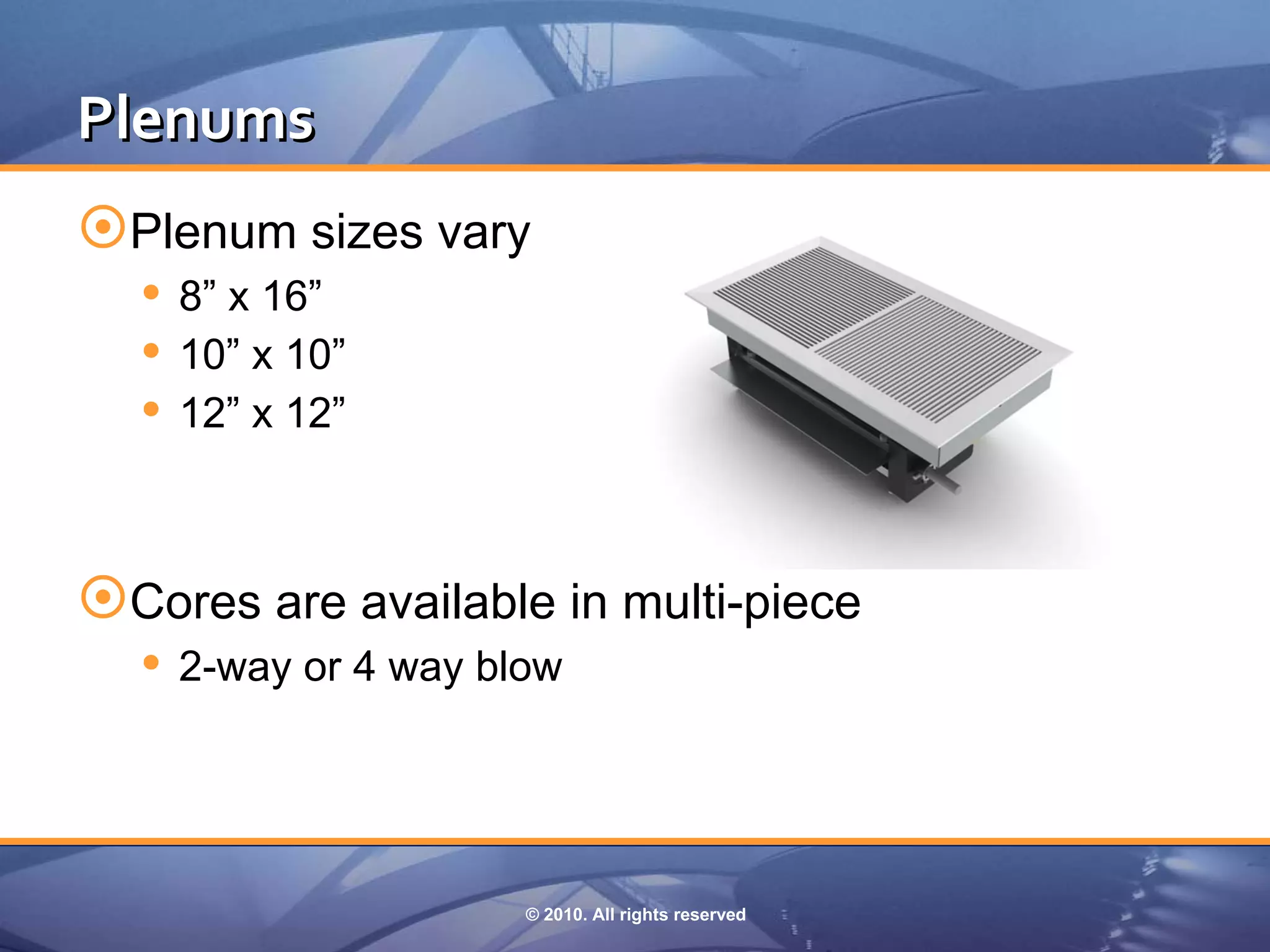
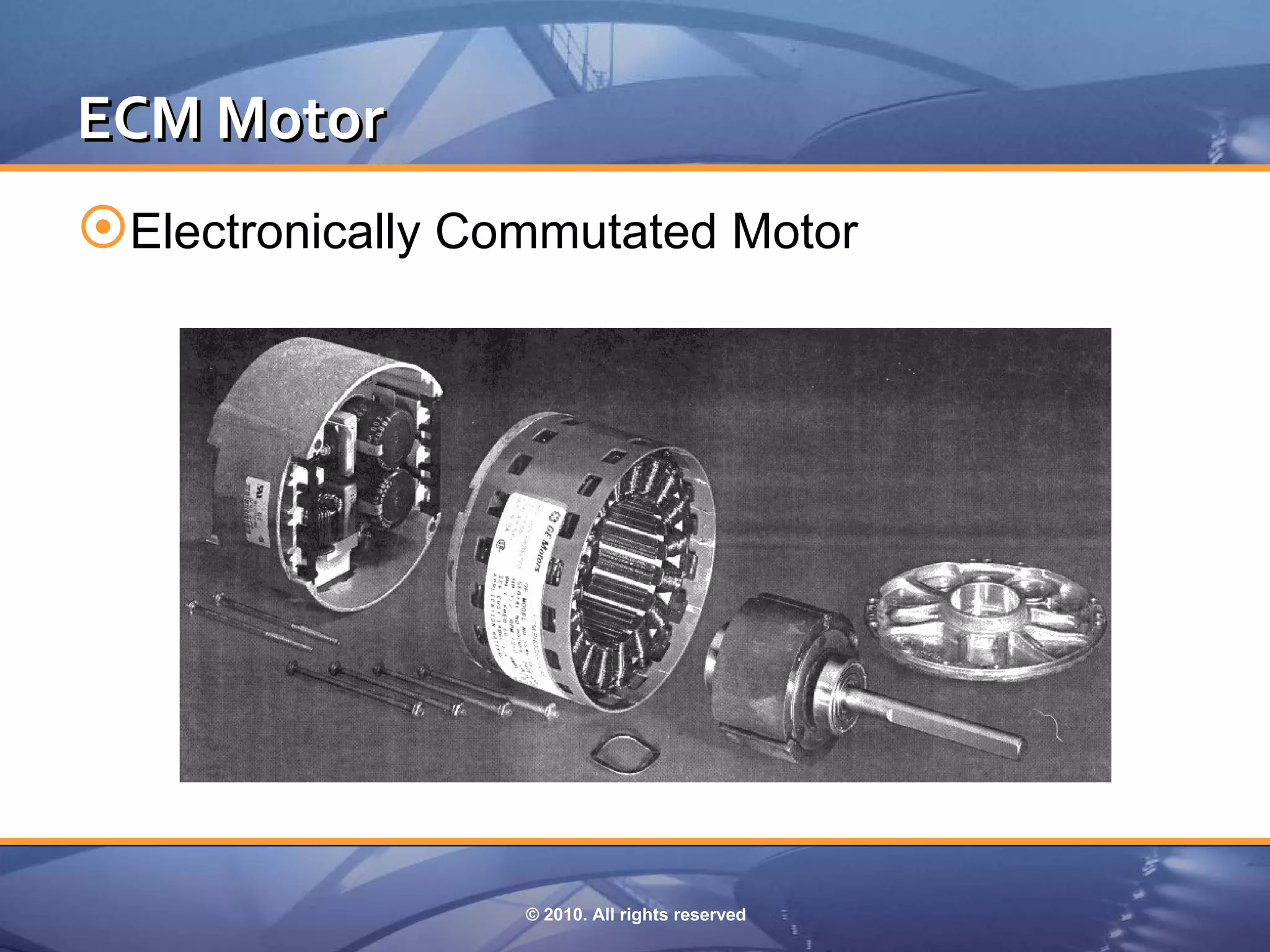
Download as PDF, PPTX
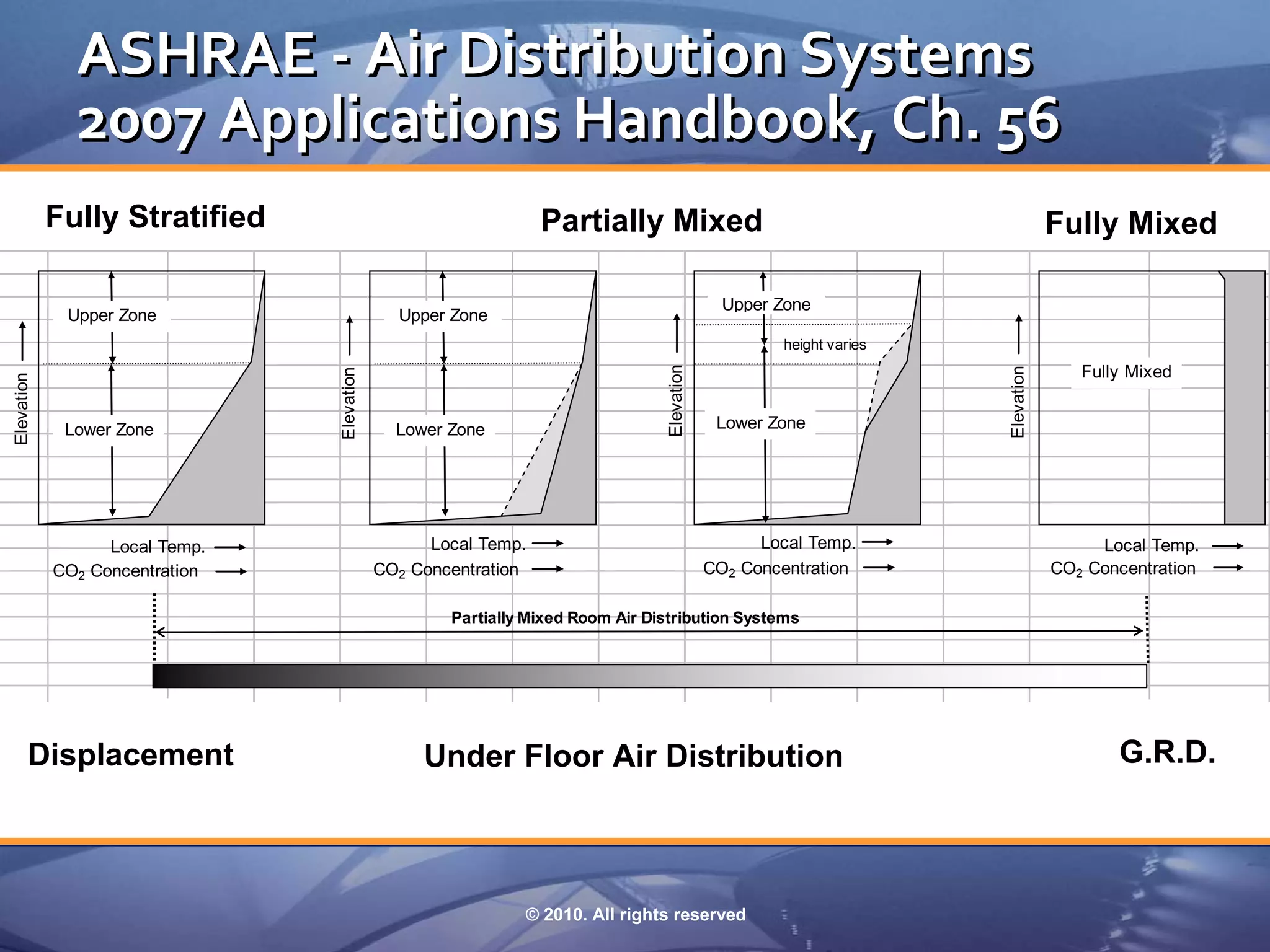
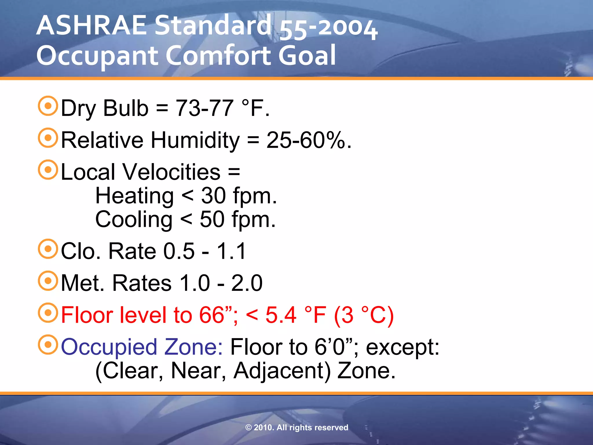
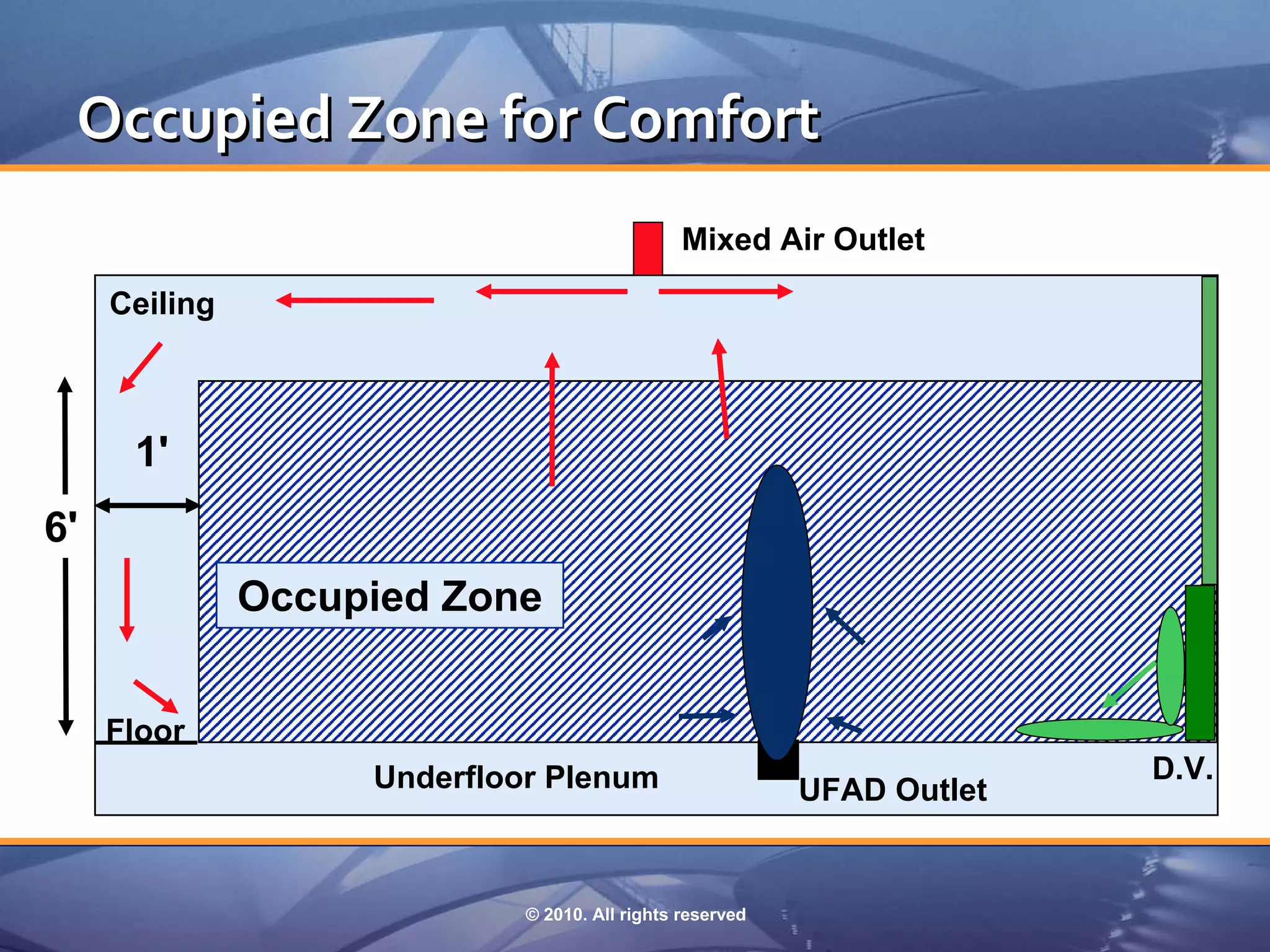
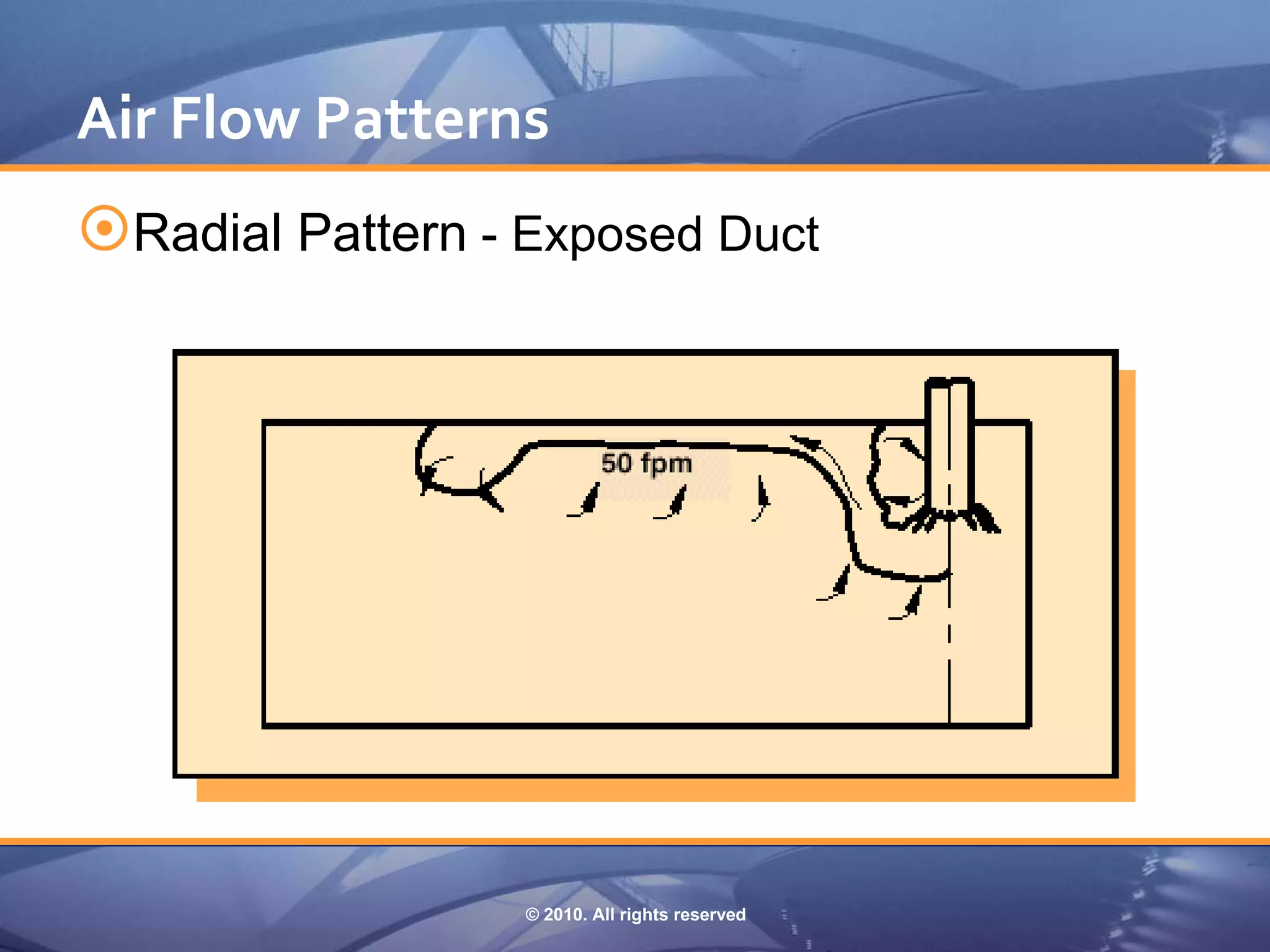
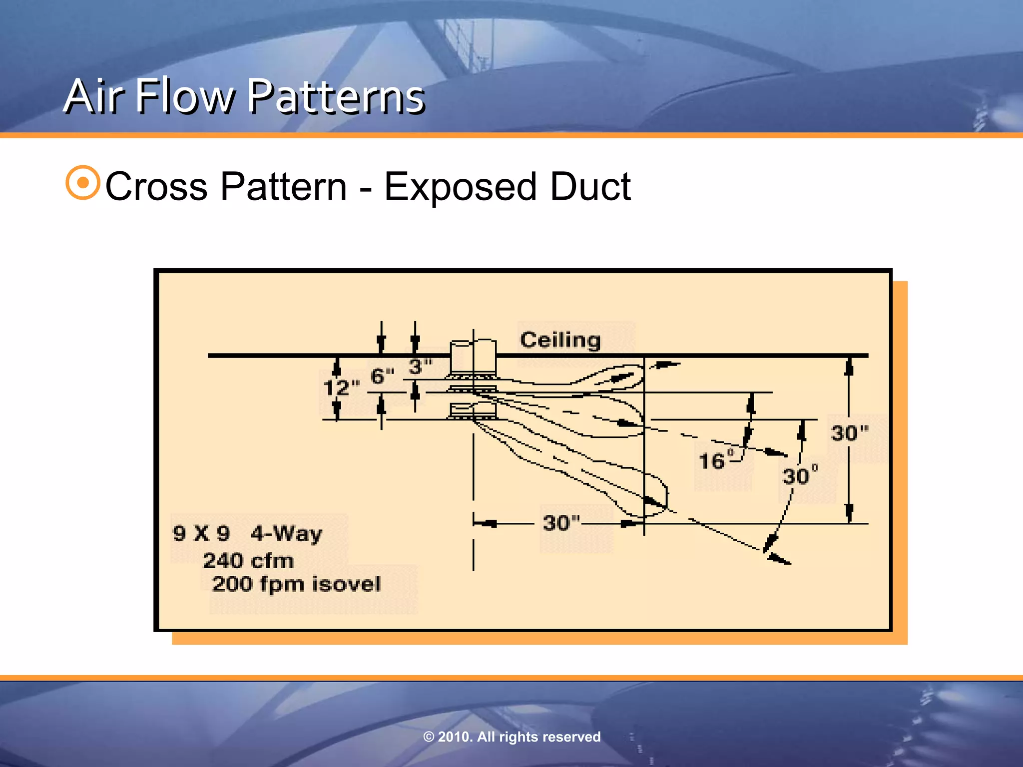
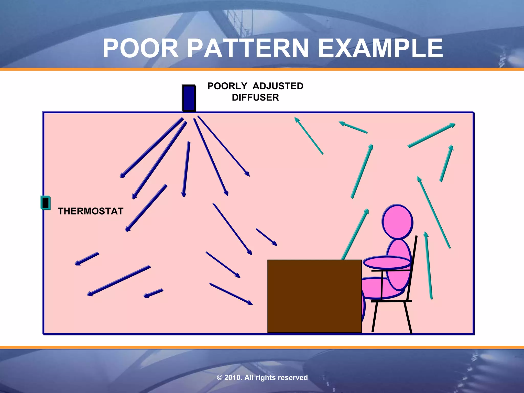
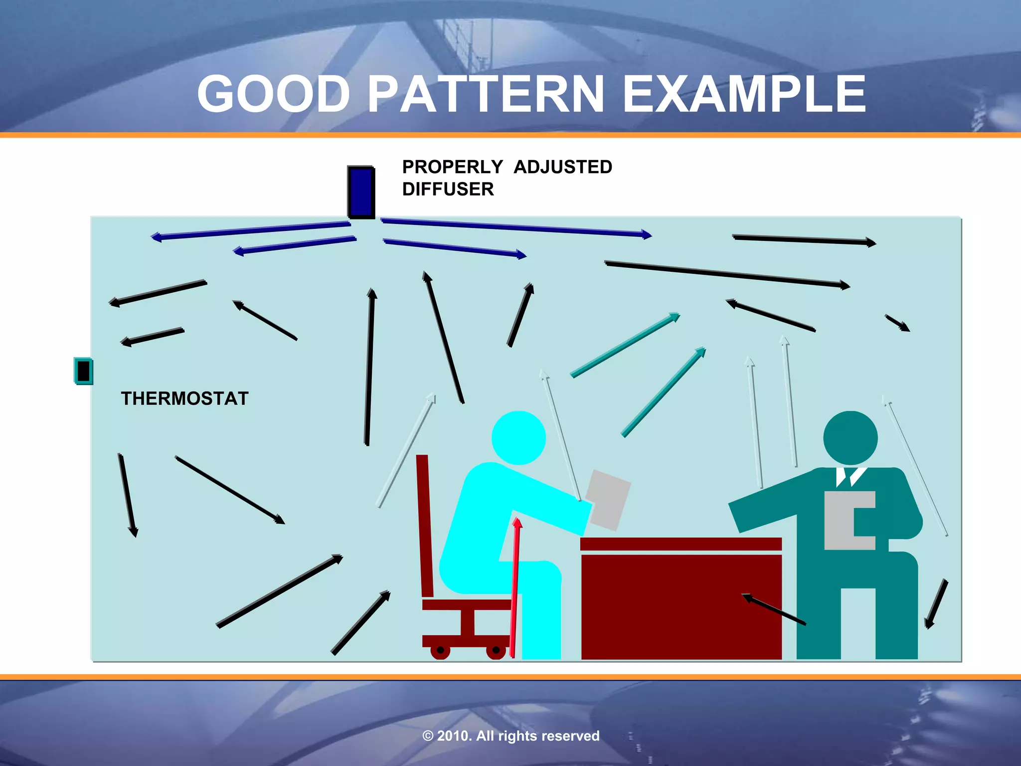
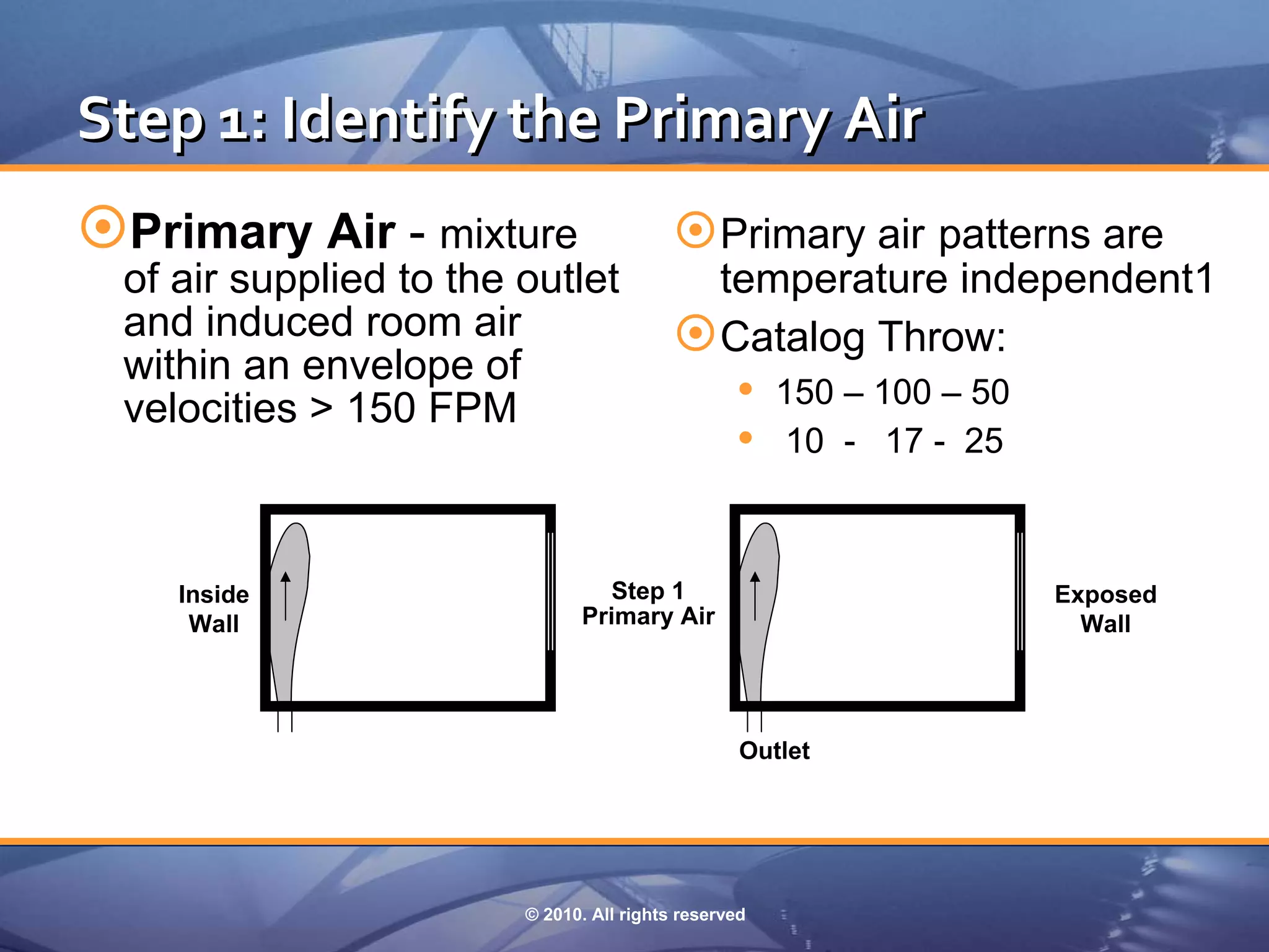
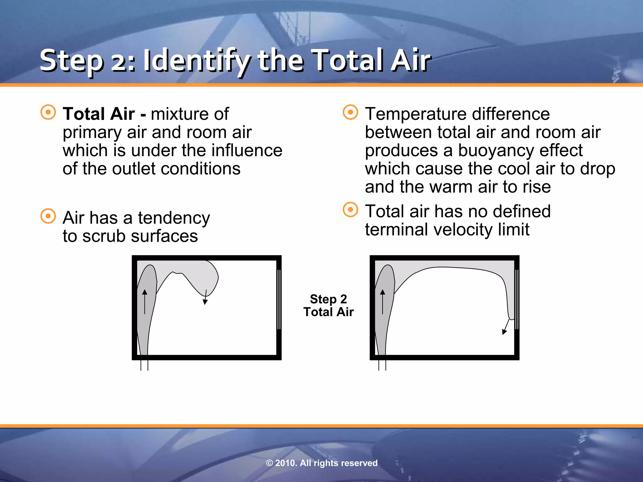
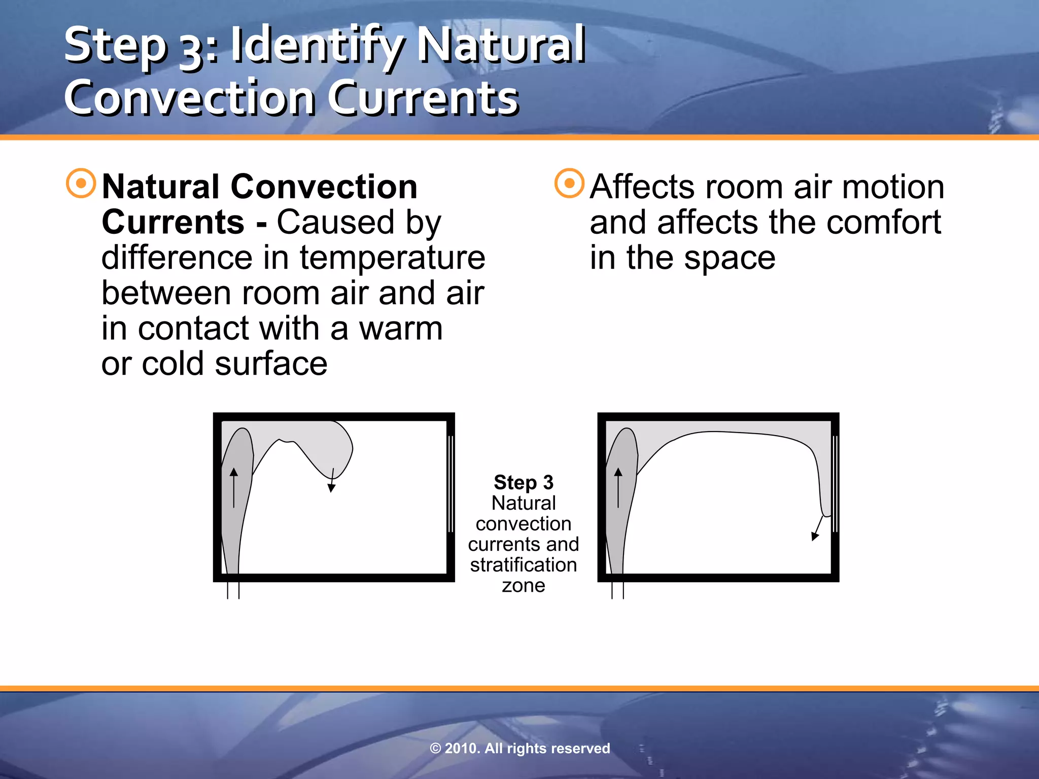
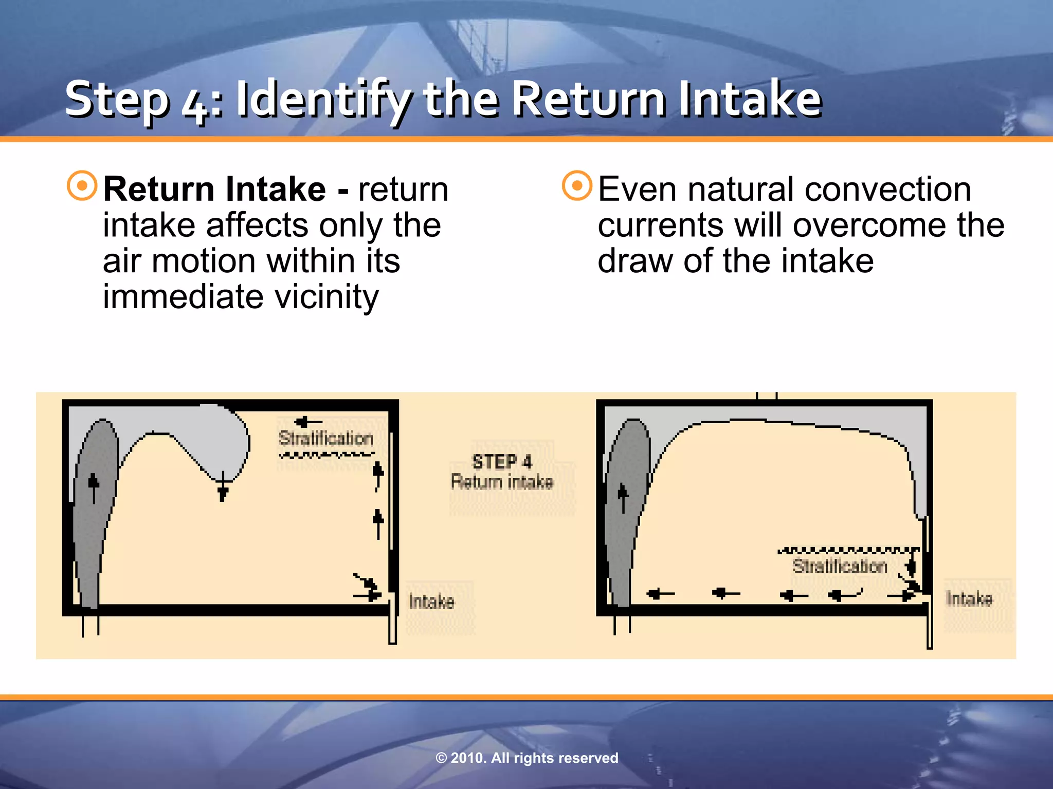
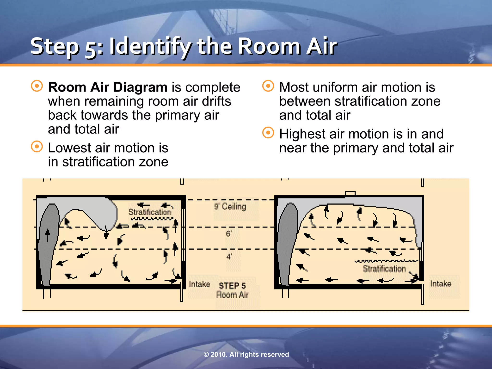
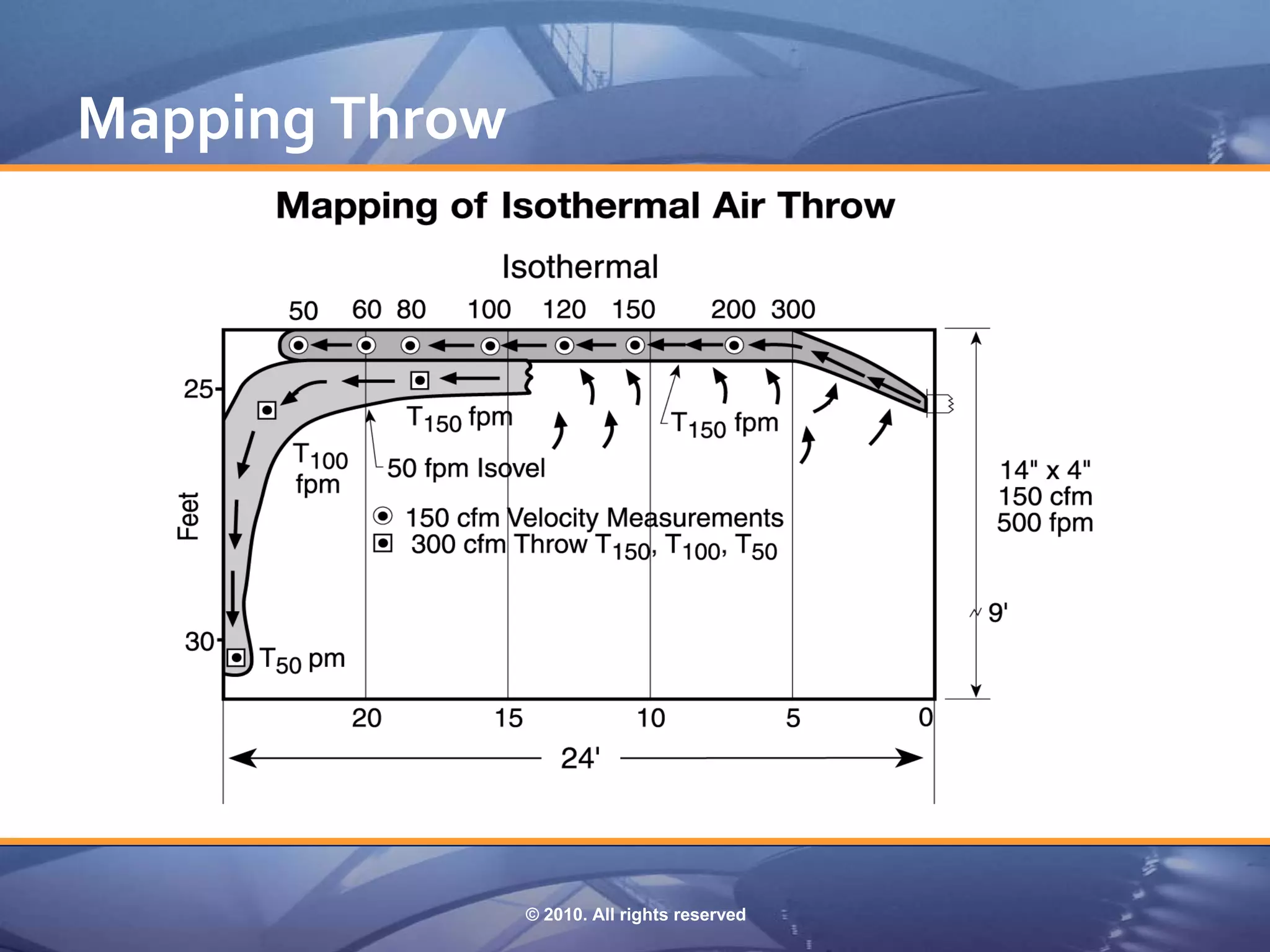
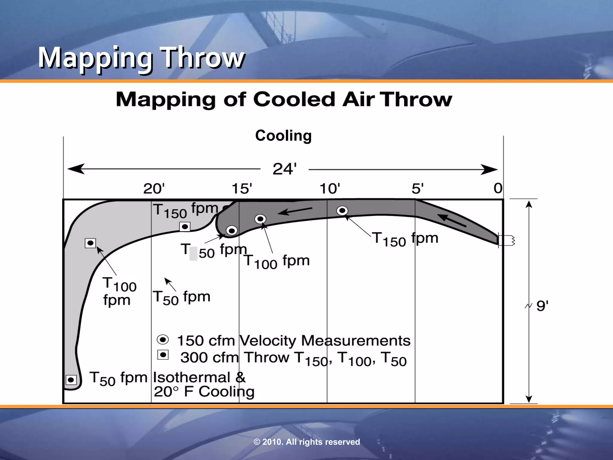
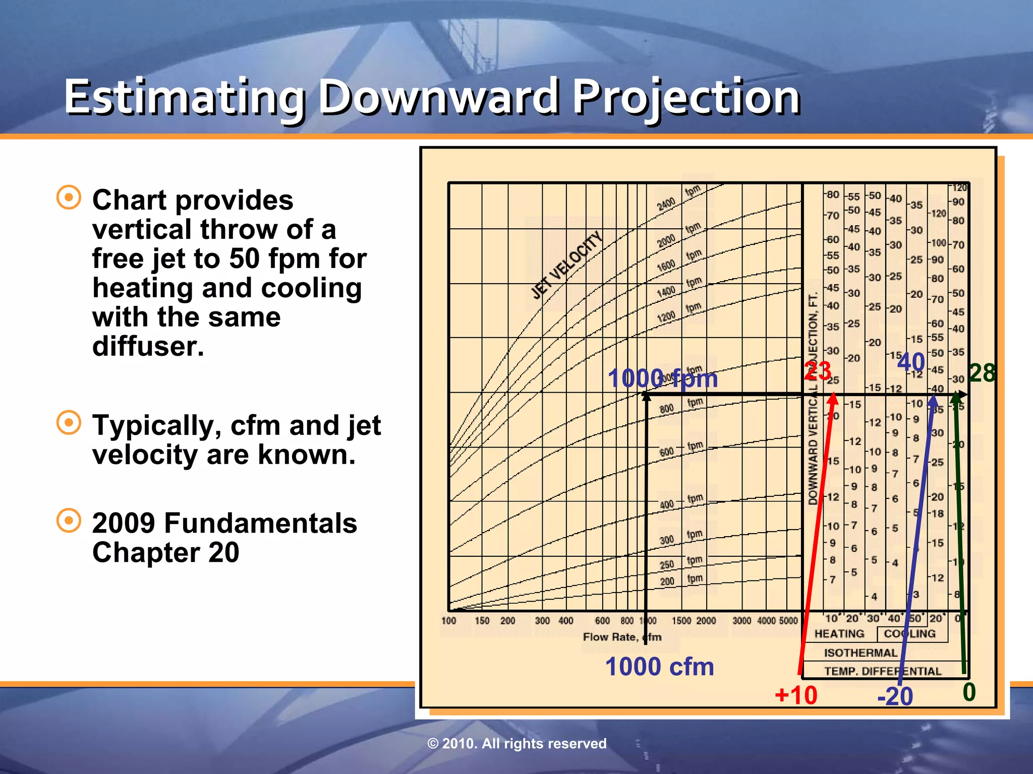
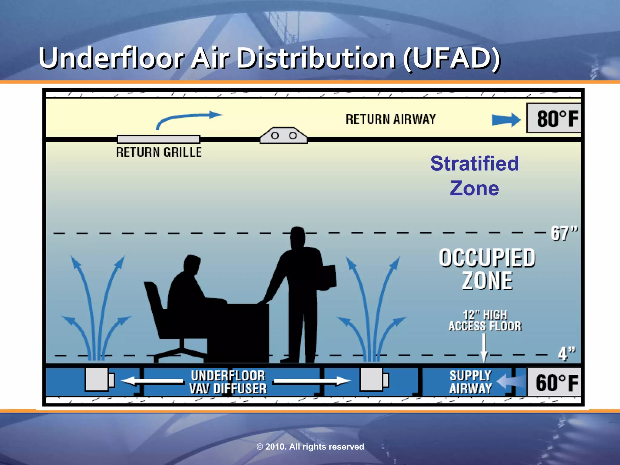
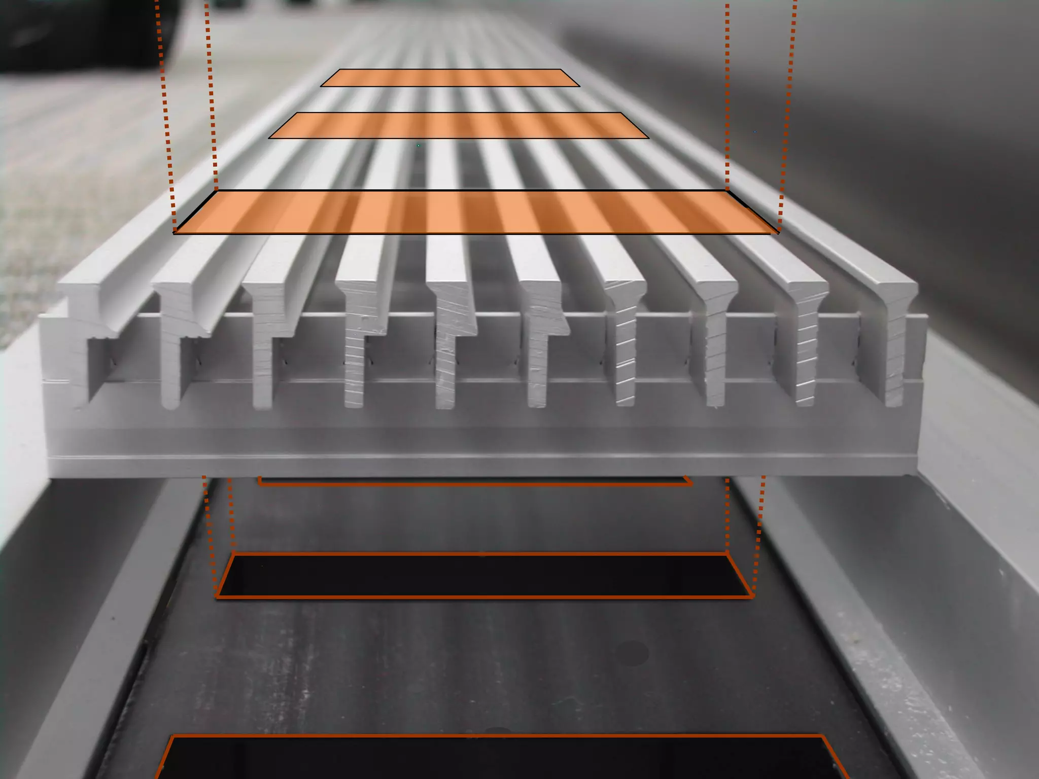
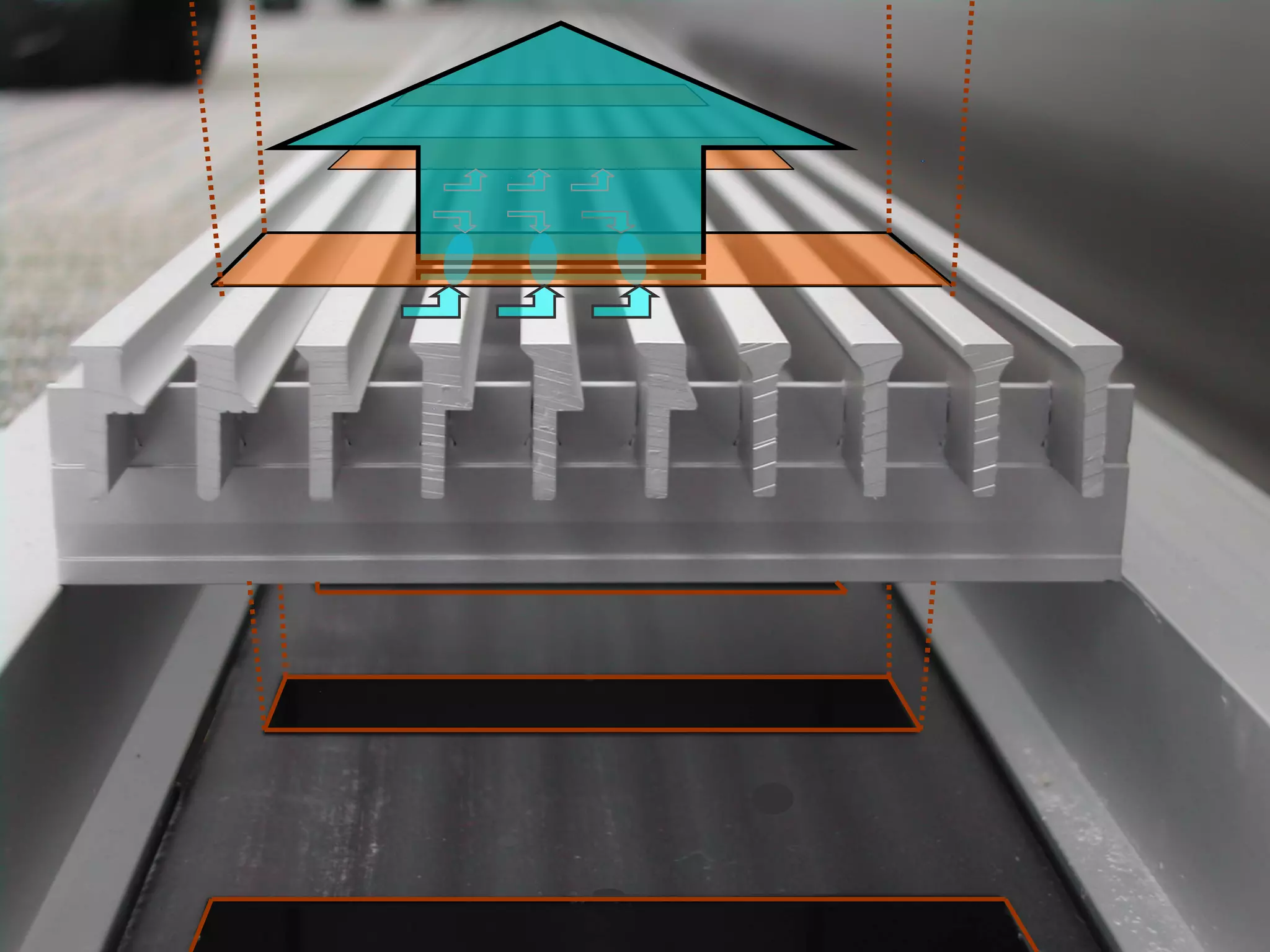
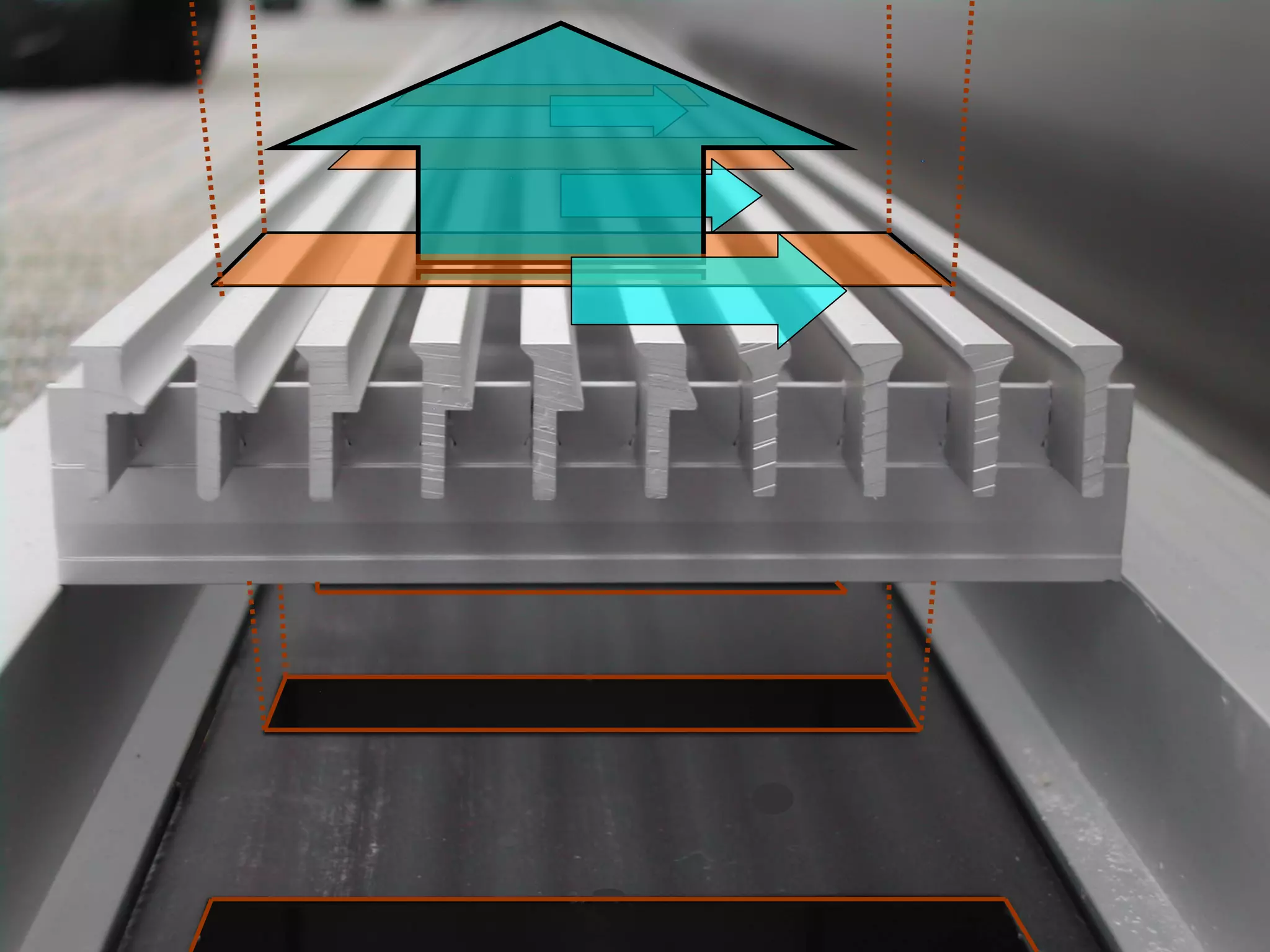
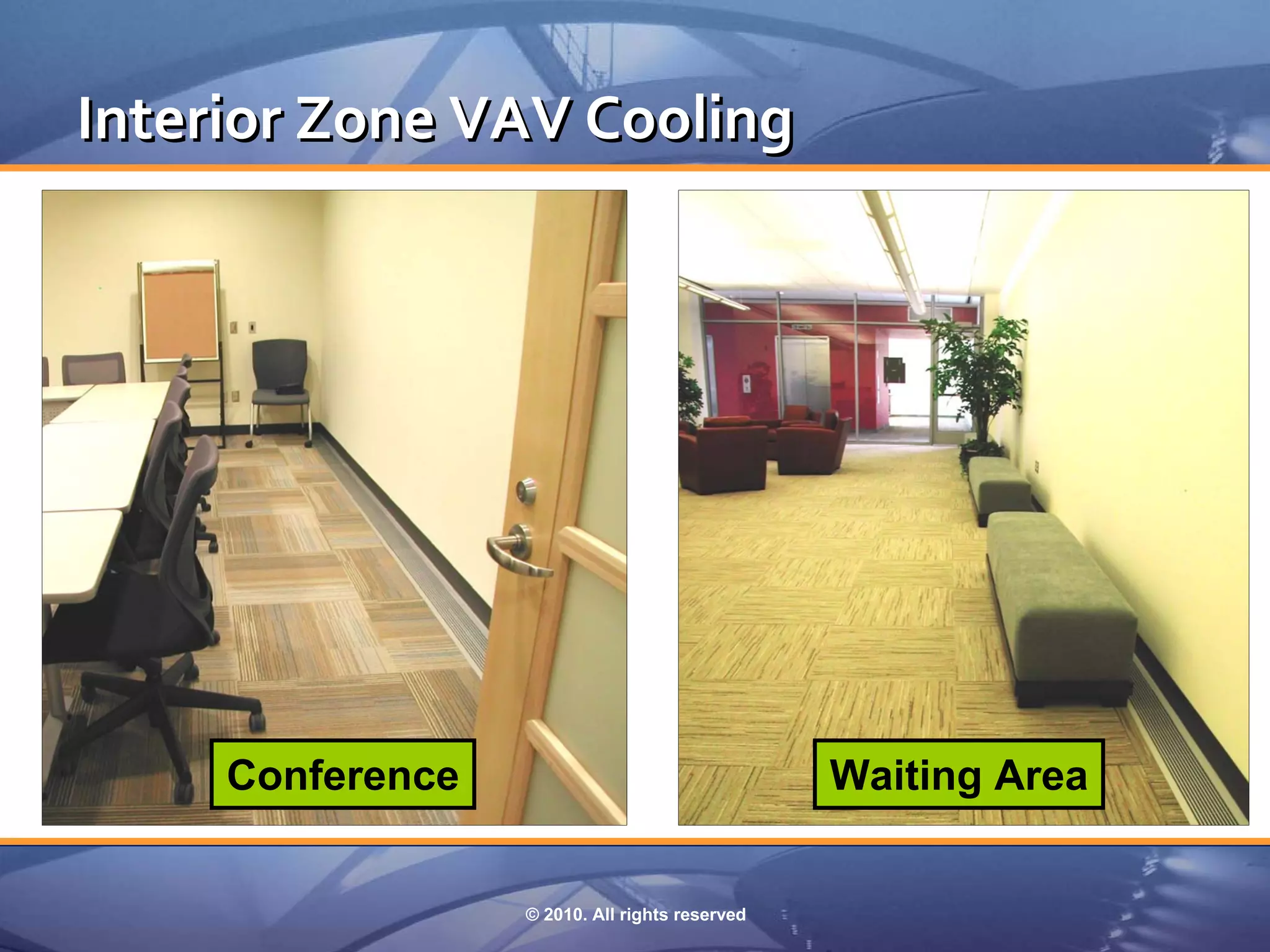
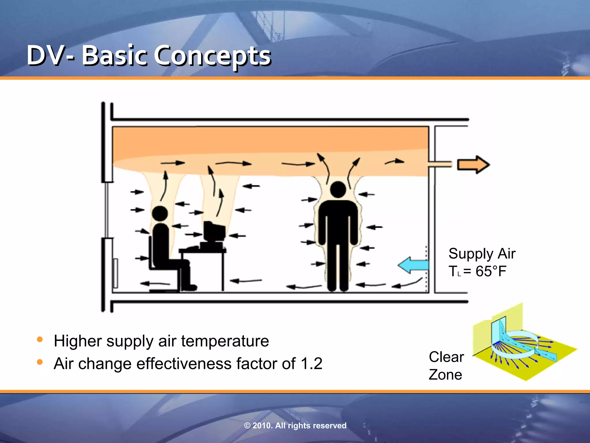
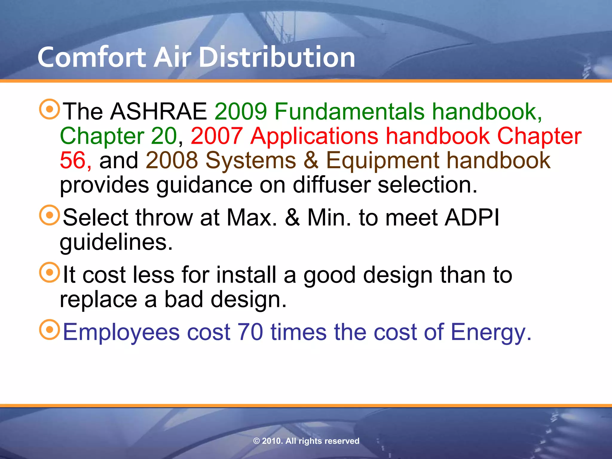


The document summarizes key concepts regarding air distribution systems and occupant comfort: 1) It describes three types of air distribution systems - fully stratified, partially mixed, and fully mixed - and discusses factors like temperature, CO2 concentration, and height variation within occupied zones. 2) It outlines the temperature, humidity, air velocity, and other criteria specified by ASHRAE Standard 55-2004 to achieve occupant comfort. 3) It provides a five-step process for mapping room air motion and visualizing air flow patterns from supply outlets or diffusers, including identifying primary air, total air, natural convection currents, return intakes, and overall room air movement.


