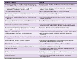
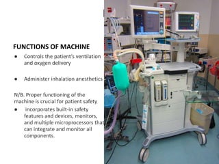
The document provides a detailed overview of anesthesia machines, highlighting their key functions, safety features, and the mechanisms for preventing hypoxia. It covers components such as gas supply systems, flow meters, vaporizers, scavenging systems, and monitoring devices that ensure patient safety and optimal performance. Additionally, it discusses various safety mechanisms, including fail-safe devices and alarms, to prevent adverse outcomes during anesthesia administration.
![Describe the safety features in an
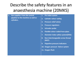
anaesthesia machine (20MKS)
1. Monitoring oxygen analyser in the breathing circuit. ASTM
standards do require that low oxygen alarm
level cannot be set below 21%. [5]
Gas volume monitoring is performed with
spirometers, This monitoring gives us a
measure of the tidal volume and minute
volume, as well as disconnection.
Airway pressure monitoring, The purpose of
airway pressure monitors is to prevent either
high (to prevent barotraumas) or low
pressures (leaks or disconnection).
Disconnection monitors are an integral
component of newer anaesthesia machines.
[51] They can be based on the gas flows (volume
measurements), pressure in the circuit, or gas
detection like capnography](https://image.slidesharecdn.com/anesthesiamachinepart1-240719032615-bafdf127/85/Anesthesia-MACHINE-and-safety-measures-in-anesthesia-machine-11-320.jpg)


![ANESTHESIA_MACHINE-_PRESSURE_REDUCING_VALVES,_FLOWMETER_AND[1].pptx](https://cdn.slidesharecdn.com/ss_thumbnails/anesthesiamachine-pressurereducingvalvesflowmeterand1-250127121142-c2585726-thumbnail.jpg?width=640&height=640&fit=bounds)


