Downloaded 160 times
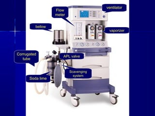
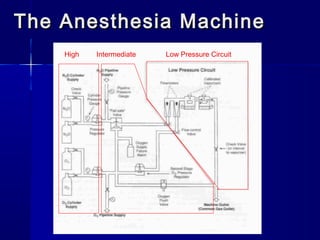
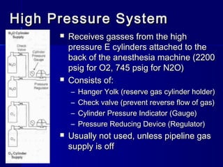
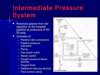
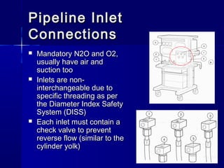


The document provides a comprehensive overview of anesthesia machines, covering components such as gas cylinders, pressure systems, and fail-safe devices, along with their functions and safety mechanisms. It details the operational characteristics of high, intermediate, and low-pressure systems, including the prevention of hypoxic mixtures and the significance of pressure reducing devices. Additional information includes vaporizer functioning, output regulations, and the structure of circle systems to avoid CO2 re-breathing.


![ANESTHESIA_MACHINE-_PRESSURE_REDUCING_VALVES,_FLOWMETER_AND[1].pptx](https://cdn.slidesharecdn.com/ss_thumbnails/anesthesiamachine-pressurereducingvalvesflowmeterand1-250127121142-c2585726-thumbnail.jpg?width=640&height=640&fit=bounds)


