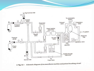
Anesthesia Machine
Compiled and Presented by:
Dr. Judith Justin M.Tech., Ph.D.,
Prof. & Head,
Department of Biomedical Instrumentation Engineering
Faculty of Engineering
Avinashilingam University
Coimbatore - 641 108
Introduction
 Anesthetic machine or Boyle's machine is used by anesthesiologists to
support administration of anaesthesia
 The most common type of anesthetic machine is designed to provide an
accurate and continuous supply of medical gases (such as oxygen and nitrous
oxide) mixed with an accurate concentration of anaesthetic vapour (such
as isoflurane), and deliver this to the patient at a safe pressure and flow.
 Modern machines incorporate a ventilator, suction unit, and patient
monitoring devices.
 The original concept of Boyle's machine was invented by the British
anesthetist Henry Boyle (1875–1941) in 1917.
machine
Components of an Anesthesia machine
 A modern anaesthesia machine includes the following components:
 Connections to piped hospital oxygen, medical air, and nitrous oxide.
 Reserve gas cylinders of oxygen, air, and nitrous oxide attached via a specific yoke with
a Bodok seal.
 A high-flow oxygen flush which provides pure oxygen at 30-75 litres/minute
 Pressure gauges, regulators and 'pop-off' valves, to protect the machine components and
patient from high-pressure gases
 Flow meters (rota meters) for oxygen, air, and nitrous oxide, low Flow meters for oxygen
nitrous oxide
 Updated vaporizers to provide accurate dosage control when using volatile anaesthetics
 An integrated ventilator to properly ventilate the patient during administration of anaesthesia
 A manual ventilation bag in combination with an Adjustable Pressure Limiting (APL) valve
 Systems for monitoring the gases being administered to, and exhaled by the patient
 Systems for monitoring the patient's heart rate, ECG, blood pressure and oxygen
saturation, in some cases with additional options for monitoring end-tidal carbon dioxide
and temperature.
Need for Anesthesia
 Anesthesia serves the following two functions:
 It ensures that the patient does not feel pain and minimizes patient discomfort;
 It provides the surgeon with favorable conditions for the surgery.
 When anesthesia is given so that the patient loses consciousness, it is called
general anesthesia. In ‘general anesthesia’, the anesthetic agent is administered
to the body so that it reaches the brain via the blood stream.
 The usual method is 'inhalation anesthesia' in which gaseous anesthetic agents
are introduced via the lungs. Examples of such agents are diethyl ether,
chloroform, halothane, cyclopropane and nitrous oxide (N20, laughing gas).
 During anesthesia, not only is the anesthetic administered in the required amount
with oxygen. Any excess carbon dioxide is also eliminated. In the superficial
stages of anesthesia, the patient can breathe for himself spontaneous ventilation.
 At a greater depth of anesthesia, it may be necessary to support the patient with
artificial ventilation known as controlled ventilation.
Delivery of Anesthesia
The anesthetic delivery system consists of an anesthesia machine, a
patient breathing circuit, a ventilator and airway equipment.
 The anesthesia machine comprises a gas supply—delivery unit and an
anesthetic vapourizer.
 The patient breathing circuit consists of a closed loop of breathing tubing,
containing two uni-directional breathing valves and an Adjustable Pressure
Limiting (APL) valve, a C02 absorber, a means for venting excess gases
(scavenging), a humidifier and a collapsible reservoir bag.
 A mechanical ventilator is used for positive pressure ventilation.
 The airway management equipment includes the mask and endo-tracheal
tube, which interface the patient with the breathing circuit.
Anesthesia Machine
 An anesthesia machine is a device which is used to deliver a precisely
known but variable gas mixture including anesthetic and life-sustaining
gases to the patient's respiratory system
 Generally, a variable concentration gas mixture of oxygen, nitrous oxide
and anesthetic vapor like ether or halothane is obtained from the
machine and is made to flow through the breathing circuit to the patient.
 Anesthesia machine is composed of two subsystems:
(i) The gas supply-delivery unit, which consists of tubing and flow
meters interconnected in parallel; and
(ii) The anesthetic vaporizers, which is used to produce an anesthetic
vapour from a volatile liquid.
Gas Supply System
 Gases are provided to the anesthesia machine from either a pressurized hospital central
supply or small storage cylinders attached to the machine.
 Centralized Supply: Centralized supply systems consist of bulk or cylinder storage for
main and reserve supply, control equipment including valves and pressure regulators, a
distribution pipeline, and numerous supply outlets.
 The system is so designed that the necessary supply of gases (oxygen and nitrous
oxide) is always available. The gas supplied by the hospital is regulated and maintained
at 275-345 kPa (40-50 psi) at the wall outlet.
 Gases are supplied to the anesthesia machine inlet from the central system via a flexible
hose connected to the operating room wall outlet.
 In order to prevent interchanging the gas supply wall outlet with the incorrect
anesthesia machine inlet, for example, nitrous oxide for oxygen, non- interchangeable
connectors are used at each end of the hose.
 The two types of non-interchangeable connections used are the Diameter Index Safety
System (DISS) and non-inter- changeable quick couplers.
 Each type of connection incorporates a male and female end that is specially designed
for each type of gas. In addition to the connector design, color-coded hoses for each
specific gas are utilized.
…..contd.
 Gas Cylinders: A second gas supply source is the cylinders located in yokes
attached to the anesthesia machine. This supply can be utilized as either the main
source when a central gas supply does not exist, or a reserve when central gas
supply is available.
 Yoke: Each anesthesia machine has at least one yoke for an oxygen cylinder but
most are provided with two. In addition to oxygen, most machine designs include a
nitrous oxide yoke. In order to prevent incorrect placement of a tank into the wrong
yoke, two pins located in the yoke must fit into corresponding holes drilled into the
tank neck. The placement of these pins and corresponding holes is unique for each
gas. This identification system, which is referred to as the 'Pin Index Safety System',
has been standardized to prevent the accidental fitting of a wrong cylinder to the
yoke.
 Pressure Regulator: Machine pressure regulators reduce cylinder gas pressures to
275 kPa (40 psi) before the gas flows through the machine. The regulator has one
high-pressure inlet, one high- pressure outlet and two-low pressure outlets. The high
pressure inlet is connected with the cylinder through a non-return valve. The non-
return valve prevents the flow into an empty cylinder or back into the central piping
system and also enables its removal and replacement when the reserve cylinder is
turned on without interrupting the supply of gas.
Gas Supply System
 Pressure Gauge: Pressure gauges are attached to the cylinders to indicate the contents of the
gases in the cylinders. For oxygen, the operating range of the gauge is 0 to 150 kg/cm2.
 Whenever the new oxygen cylinder is hooked up and taken in line, the indicator should be above this
mark. With the gradual usage of the gas, the reading would drop gradually.
 When the indicator shows that the pressure has fallen below the minimum level of acceptance, the
cylinder should be refilled. If for any reason, the pressure gauge shows a reading above
150 kg/cm2 during use, the cylinder should be disconnected immediately and replaced.
 Fail Safe System: From the supply, the gas flows into the inlet of the anesthesia machine and is directed
through the pressure safety system (fail-safe system) towards the flow delivery unit.
 The pressure safety system will not allow nitrous oxide to flow without an oxygen supply pressure in the
machine.
 The fail-safe system consists of a master pressure regulator valve located in the oxygen supply line. From
the master regulator, a reference pressure is provided to the slave regulator valve controlling the pressure
and flow of the nitrous oxide line. When sufficient oxygen pressure of 275 kPa (40 psi) is present in the
master regulator, the reference pressure enables the slave regulator valve to open and for nitrous oxide to
flow. Unfortunately, pure nitrous oxide can be delivered with only oxygen supply pressure present;
oxygen flow is not required.
Gas Delivery System (Gas
proportioning)
 Regulations now require oxygen-nitrous oxide ratio safeguards, which need a
minimum continuous low flow of oxygen varying from 200 to 300 mL/min, as
indicated by the low-flow rotameter. In newly designed machines, ingenious
mechanical devices prevent the delivery of gas mixtures with an oxygen
concentration below a low limit. Oxygen-nitrous oxide ratios vary from 25:75 to
30:70.
 Gas Delivery Units: From the fail-safe system, the gas is directed to the flow
delivery unit. Two methods have been used to accomplish delivery and control of
the gas mixture: gas proportioning and gas mixing.
 In a gas proportioning system, the delivered concentration of each gas constituent
is the function of a pre-determined, precisely controlled ratio of proportionality
which is independent of the total gas flow. For example, for a desired mixture of
70% nitrous oxide and 30% oxygen, the metered ratio of mass delivery will always
be 7:3, regardless of the total flow rate. Concentration is only a function of the
proportional relationship between constituents. It does not rely on setting individual
gas flows. An oxygen-nitrous oxide bleeder used in a manner similar to the
oxygen— air blenders commonly used with mechanical ventilators performs this
function.
Gas Delivery System (Gas mixing)
 Current anesthesia machines use gas mixing. In this technique, the flow rate of
each constituent is independently controlled and measured by a delivery unit
consisting of a needle valve and a rotameter. The needle valve functions as a
flow controller and a means of turning the gas on and off. The rotameter is a
variable orifice flow meter and consists of a transparent tube with a tapered
internal diameter and a floating bobbin flow indicator.
 During the administration of anesthesia, it may be necessary to fill the patient
breathing circuit with oxygen at a rate higher than what the gas delivery unit can
supply. For example, such a situation exists any time the patient is disconnected
to the breathing circuit. This higher flow of oxygen is supplied via the oxygen
flush valve and line. The oxygen flush system provides a high flow ranging from
35 to 75 L/min at a high pressure (20-45 psi, 270-590 kPa) directly into the
patient breathing circuit.
 Each gas has a specific delivery unit. These units are connected in parallel and
exhaust into a common manifold prior to leaving the machine. The final
concentration and total flow determined by mixing the component flows are
dependent functions and subject to the accuracy of the control and measurement
equipment.
Vapour delivery
 Liquids that possess anesthetic properties are too potent (strong) to be used as
pure vapours. They are diluted in a carrier gas such as air and/or oxygen, or
nitrous oxide and oxygen. The device that allows vaporization of the liquid
anesthetic agent and its subsequent admixture with a carrier gas for
administration to a patient is called a 'vaporizer'. Vaporizers produce an
accurate gaseous concentration from a volatile liquid anesthetic. The
anaesthetic vapour can then be safely added to the previously metered oxygen
and nitrous oxide as the mixture leaves the mixing manifold.
 Vaporizers are available in one of the two basic designs: the flow meter
controlled or the concentration-calibrated. In either device, the anesthetic
vapours are picked up from the vaporizer by a carrier gas consisting either of
pure oxygen or an oxygen-nitrous oxide mixture that bubbles through or
passes over the liquid. The liquid surface area to gas interface is designed to
ensure the most efficient vaporization process.
…contd.
 Vapourization produces a drop in liquid temperature.
 As liquid temperature decreases, a thermal gradient is established between the liquid and the
surroundings.
 This results in a decrease in the quantity of the vapour produced. In order to maintain the
performance of the vapourizer, the temperature drop is minimized or prevented by the
incorporation of a thermal source.
 This is achieved by using a water bath or surrounding the vapourizing liquid with a heating
element.
 These devices may also control the temperature of the carrier gas entering the vapourizer.
 The materials selected for vapourizer construction require both a high specific heat and high
thermal conductivity.
 Materials with high specific heats will change temperature more slowly and maintain an
appropriate thermal inertia.
 The higher the thermal conductivity, the higher the conduction of heat from the surroundings.
 Because of its availability and lower cost, copper is one of the most common materials used.
 Copper has a moderate specific heat and a high thermal conductivity.
 Earlier vapourizers were called “copper kettles".
 In order to provide a stable and predictable concentration of anaesthetic
vapour, the vaporizers include a suitable method of obtaining calibrated
dilution of vapour to avoid administration of too powerful volatile anaesthetic
agents to the patient.
 This can be done by several means and the vaporizers are accordingly
classified into two categories:
Variable Bypass Vaporizer
Measured flow vaporizer
Variable bypass vaporizer
 Variable Bypass Vaporizer: Here the carrier gas flow from the flowmeter is split
into two streams in a known ratio: one stream which is called 'chamber flow', flows
over the liquid agent while the other stream goes through the bypass path and does
not enter the vaporizing chamber. The final concentration can be controlled by
varying the splitting ratio between the vapourizer gas and the bypass gas using an
adjustable valve.
 The splitting ratio of the two flows depends on the ratio of resistances to their flow,
which is controlled by the concentration control dial and the
automatic temperature compensation valve.
 Less than 20% of the gas becomes enriched-saturated with
vapour and more than 80% is bypassed, to rejoin at the
vapourizer outlet.
 The output of current variable bypass vapourizers is relatively constant over the
range of fresh gas flows from approximately 250 mL/min to 15 L/min.
A flow splitting valve that can be rotated to alter the
relative diameters of the vapourizer and bypass channels
Variable bypass vaporizer ….contd.
 The output of vapourizers is linear at the ambient temperature (2°-35°C)
due to automatic temperature compensating devices that increase carrier
gas flow as the liquid volatile agent temperature decreases.
 Also, they are composed of metals with high specific heat and thermal
conductivity.
 Check valves are provided to prevent back pressure effect on the
vapourizer from the breathing circuit due to positive pressure
ventilation.
Measured flow Vaporizer
 The anaesthetic agent is heated to a temperature above the boiling point (so
that it behaves as a gas) and is then metered into the fresh gas flow.
 Various anaesthetic agents have widely different potencies and physical
properties and hence require vaporizers constructed specifically for each
agent. They are thus 'agent-specific'.
 They are only calibrated for a single gas, usually with keyed filters that
decrease the likelihood of filling the vaporizers with the wrong agent.
Measured flow Vaporizer
 Vaporizers are provided with various safety related inter-locks which ensure
that:
Only one vaporizer is turned on;
Gas enters only through the one which is on;
Trace vapour output is minimized when the vaporizer is off;
Vaporizers are locked into the gas circuit, thus ensuring that they
are seated correctly; and
Other important safety features are followed including keyed
filters and secured mounting to minimize tipping (tilting) which
may obstruct the working of the valves.
Delivery System
 Patient Breathing System: The function of a patient breathing system is to
deliver anesthetic and respiratory gases to and from the patient. It describes
both the mode of operation and the apparatus by which inhalation agents are
delivered to the patient. The breathing system may be
 Rebreathing Type: This refers to re-breathing of some or all of the
previously exhaled gases, including carbon dioxide and water vapour.
 Non-rebreathing Type: In this a fresh gas supply is delivered to the patient
and re-breathing of previously exhaled gases is prevented. Usually, non-
rebreathing type systems are applied in practice. This is achieved by using:
 Non-rebreathing uni-directional valve;
 Carbon dioxide absorption system; involving;
 Uni-directional (circle) system; and
 Bi-directional (to-and-fro) system.

Anesthesia machine

  • 1.
    Anesthesia Machine Compiled andPresented by: Dr. Judith Justin M.Tech., Ph.D., Prof. & Head, Department of Biomedical Instrumentation Engineering Faculty of Engineering Avinashilingam University Coimbatore - 641 108
  • 2.
    Introduction  Anesthetic machineor Boyle's machine is used by anesthesiologists to support administration of anaesthesia  The most common type of anesthetic machine is designed to provide an accurate and continuous supply of medical gases (such as oxygen and nitrous oxide) mixed with an accurate concentration of anaesthetic vapour (such as isoflurane), and deliver this to the patient at a safe pressure and flow.  Modern machines incorporate a ventilator, suction unit, and patient monitoring devices.  The original concept of Boyle's machine was invented by the British anesthetist Henry Boyle (1875–1941) in 1917.
  • 3.
  • 4.
    Components of anAnesthesia machine  A modern anaesthesia machine includes the following components:  Connections to piped hospital oxygen, medical air, and nitrous oxide.  Reserve gas cylinders of oxygen, air, and nitrous oxide attached via a specific yoke with a Bodok seal.  A high-flow oxygen flush which provides pure oxygen at 30-75 litres/minute  Pressure gauges, regulators and 'pop-off' valves, to protect the machine components and patient from high-pressure gases  Flow meters (rota meters) for oxygen, air, and nitrous oxide, low Flow meters for oxygen nitrous oxide  Updated vaporizers to provide accurate dosage control when using volatile anaesthetics  An integrated ventilator to properly ventilate the patient during administration of anaesthesia  A manual ventilation bag in combination with an Adjustable Pressure Limiting (APL) valve  Systems for monitoring the gases being administered to, and exhaled by the patient  Systems for monitoring the patient's heart rate, ECG, blood pressure and oxygen saturation, in some cases with additional options for monitoring end-tidal carbon dioxide and temperature.
  • 5.
    Need for Anesthesia Anesthesia serves the following two functions:  It ensures that the patient does not feel pain and minimizes patient discomfort;  It provides the surgeon with favorable conditions for the surgery.  When anesthesia is given so that the patient loses consciousness, it is called general anesthesia. In ‘general anesthesia’, the anesthetic agent is administered to the body so that it reaches the brain via the blood stream.  The usual method is 'inhalation anesthesia' in which gaseous anesthetic agents are introduced via the lungs. Examples of such agents are diethyl ether, chloroform, halothane, cyclopropane and nitrous oxide (N20, laughing gas).  During anesthesia, not only is the anesthetic administered in the required amount with oxygen. Any excess carbon dioxide is also eliminated. In the superficial stages of anesthesia, the patient can breathe for himself spontaneous ventilation.  At a greater depth of anesthesia, it may be necessary to support the patient with artificial ventilation known as controlled ventilation.
  • 6.
    Delivery of Anesthesia Theanesthetic delivery system consists of an anesthesia machine, a patient breathing circuit, a ventilator and airway equipment.  The anesthesia machine comprises a gas supply—delivery unit and an anesthetic vapourizer.  The patient breathing circuit consists of a closed loop of breathing tubing, containing two uni-directional breathing valves and an Adjustable Pressure Limiting (APL) valve, a C02 absorber, a means for venting excess gases (scavenging), a humidifier and a collapsible reservoir bag.  A mechanical ventilator is used for positive pressure ventilation.  The airway management equipment includes the mask and endo-tracheal tube, which interface the patient with the breathing circuit.
  • 7.
    Anesthesia Machine  Ananesthesia machine is a device which is used to deliver a precisely known but variable gas mixture including anesthetic and life-sustaining gases to the patient's respiratory system  Generally, a variable concentration gas mixture of oxygen, nitrous oxide and anesthetic vapor like ether or halothane is obtained from the machine and is made to flow through the breathing circuit to the patient.  Anesthesia machine is composed of two subsystems: (i) The gas supply-delivery unit, which consists of tubing and flow meters interconnected in parallel; and (ii) The anesthetic vaporizers, which is used to produce an anesthetic vapour from a volatile liquid.
  • 8.
    Gas Supply System Gases are provided to the anesthesia machine from either a pressurized hospital central supply or small storage cylinders attached to the machine.  Centralized Supply: Centralized supply systems consist of bulk or cylinder storage for main and reserve supply, control equipment including valves and pressure regulators, a distribution pipeline, and numerous supply outlets.  The system is so designed that the necessary supply of gases (oxygen and nitrous oxide) is always available. The gas supplied by the hospital is regulated and maintained at 275-345 kPa (40-50 psi) at the wall outlet.  Gases are supplied to the anesthesia machine inlet from the central system via a flexible hose connected to the operating room wall outlet.  In order to prevent interchanging the gas supply wall outlet with the incorrect anesthesia machine inlet, for example, nitrous oxide for oxygen, non- interchangeable connectors are used at each end of the hose.  The two types of non-interchangeable connections used are the Diameter Index Safety System (DISS) and non-inter- changeable quick couplers.  Each type of connection incorporates a male and female end that is specially designed for each type of gas. In addition to the connector design, color-coded hoses for each specific gas are utilized.
  • 9.
    …..contd.  Gas Cylinders:A second gas supply source is the cylinders located in yokes attached to the anesthesia machine. This supply can be utilized as either the main source when a central gas supply does not exist, or a reserve when central gas supply is available.  Yoke: Each anesthesia machine has at least one yoke for an oxygen cylinder but most are provided with two. In addition to oxygen, most machine designs include a nitrous oxide yoke. In order to prevent incorrect placement of a tank into the wrong yoke, two pins located in the yoke must fit into corresponding holes drilled into the tank neck. The placement of these pins and corresponding holes is unique for each gas. This identification system, which is referred to as the 'Pin Index Safety System', has been standardized to prevent the accidental fitting of a wrong cylinder to the yoke.  Pressure Regulator: Machine pressure regulators reduce cylinder gas pressures to 275 kPa (40 psi) before the gas flows through the machine. The regulator has one high-pressure inlet, one high- pressure outlet and two-low pressure outlets. The high pressure inlet is connected with the cylinder through a non-return valve. The non- return valve prevents the flow into an empty cylinder or back into the central piping system and also enables its removal and replacement when the reserve cylinder is turned on without interrupting the supply of gas.
  • 11.
    Gas Supply System Pressure Gauge: Pressure gauges are attached to the cylinders to indicate the contents of the gases in the cylinders. For oxygen, the operating range of the gauge is 0 to 150 kg/cm2.  Whenever the new oxygen cylinder is hooked up and taken in line, the indicator should be above this mark. With the gradual usage of the gas, the reading would drop gradually.  When the indicator shows that the pressure has fallen below the minimum level of acceptance, the cylinder should be refilled. If for any reason, the pressure gauge shows a reading above 150 kg/cm2 during use, the cylinder should be disconnected immediately and replaced.  Fail Safe System: From the supply, the gas flows into the inlet of the anesthesia machine and is directed through the pressure safety system (fail-safe system) towards the flow delivery unit.  The pressure safety system will not allow nitrous oxide to flow without an oxygen supply pressure in the machine.  The fail-safe system consists of a master pressure regulator valve located in the oxygen supply line. From the master regulator, a reference pressure is provided to the slave regulator valve controlling the pressure and flow of the nitrous oxide line. When sufficient oxygen pressure of 275 kPa (40 psi) is present in the master regulator, the reference pressure enables the slave regulator valve to open and for nitrous oxide to flow. Unfortunately, pure nitrous oxide can be delivered with only oxygen supply pressure present; oxygen flow is not required.
  • 12.
    Gas Delivery System(Gas proportioning)  Regulations now require oxygen-nitrous oxide ratio safeguards, which need a minimum continuous low flow of oxygen varying from 200 to 300 mL/min, as indicated by the low-flow rotameter. In newly designed machines, ingenious mechanical devices prevent the delivery of gas mixtures with an oxygen concentration below a low limit. Oxygen-nitrous oxide ratios vary from 25:75 to 30:70.  Gas Delivery Units: From the fail-safe system, the gas is directed to the flow delivery unit. Two methods have been used to accomplish delivery and control of the gas mixture: gas proportioning and gas mixing.  In a gas proportioning system, the delivered concentration of each gas constituent is the function of a pre-determined, precisely controlled ratio of proportionality which is independent of the total gas flow. For example, for a desired mixture of 70% nitrous oxide and 30% oxygen, the metered ratio of mass delivery will always be 7:3, regardless of the total flow rate. Concentration is only a function of the proportional relationship between constituents. It does not rely on setting individual gas flows. An oxygen-nitrous oxide bleeder used in a manner similar to the oxygen— air blenders commonly used with mechanical ventilators performs this function.
  • 13.
    Gas Delivery System(Gas mixing)  Current anesthesia machines use gas mixing. In this technique, the flow rate of each constituent is independently controlled and measured by a delivery unit consisting of a needle valve and a rotameter. The needle valve functions as a flow controller and a means of turning the gas on and off. The rotameter is a variable orifice flow meter and consists of a transparent tube with a tapered internal diameter and a floating bobbin flow indicator.  During the administration of anesthesia, it may be necessary to fill the patient breathing circuit with oxygen at a rate higher than what the gas delivery unit can supply. For example, such a situation exists any time the patient is disconnected to the breathing circuit. This higher flow of oxygen is supplied via the oxygen flush valve and line. The oxygen flush system provides a high flow ranging from 35 to 75 L/min at a high pressure (20-45 psi, 270-590 kPa) directly into the patient breathing circuit.  Each gas has a specific delivery unit. These units are connected in parallel and exhaust into a common manifold prior to leaving the machine. The final concentration and total flow determined by mixing the component flows are dependent functions and subject to the accuracy of the control and measurement equipment.
  • 14.
    Vapour delivery  Liquidsthat possess anesthetic properties are too potent (strong) to be used as pure vapours. They are diluted in a carrier gas such as air and/or oxygen, or nitrous oxide and oxygen. The device that allows vaporization of the liquid anesthetic agent and its subsequent admixture with a carrier gas for administration to a patient is called a 'vaporizer'. Vaporizers produce an accurate gaseous concentration from a volatile liquid anesthetic. The anaesthetic vapour can then be safely added to the previously metered oxygen and nitrous oxide as the mixture leaves the mixing manifold.  Vaporizers are available in one of the two basic designs: the flow meter controlled or the concentration-calibrated. In either device, the anesthetic vapours are picked up from the vaporizer by a carrier gas consisting either of pure oxygen or an oxygen-nitrous oxide mixture that bubbles through or passes over the liquid. The liquid surface area to gas interface is designed to ensure the most efficient vaporization process.
  • 15.
    …contd.  Vapourization producesa drop in liquid temperature.  As liquid temperature decreases, a thermal gradient is established between the liquid and the surroundings.  This results in a decrease in the quantity of the vapour produced. In order to maintain the performance of the vapourizer, the temperature drop is minimized or prevented by the incorporation of a thermal source.  This is achieved by using a water bath or surrounding the vapourizing liquid with a heating element.  These devices may also control the temperature of the carrier gas entering the vapourizer.  The materials selected for vapourizer construction require both a high specific heat and high thermal conductivity.  Materials with high specific heats will change temperature more slowly and maintain an appropriate thermal inertia.  The higher the thermal conductivity, the higher the conduction of heat from the surroundings.  Because of its availability and lower cost, copper is one of the most common materials used.  Copper has a moderate specific heat and a high thermal conductivity.  Earlier vapourizers were called “copper kettles".
  • 16.
     In orderto provide a stable and predictable concentration of anaesthetic vapour, the vaporizers include a suitable method of obtaining calibrated dilution of vapour to avoid administration of too powerful volatile anaesthetic agents to the patient.  This can be done by several means and the vaporizers are accordingly classified into two categories: Variable Bypass Vaporizer Measured flow vaporizer
  • 17.
    Variable bypass vaporizer Variable Bypass Vaporizer: Here the carrier gas flow from the flowmeter is split into two streams in a known ratio: one stream which is called 'chamber flow', flows over the liquid agent while the other stream goes through the bypass path and does not enter the vaporizing chamber. The final concentration can be controlled by varying the splitting ratio between the vapourizer gas and the bypass gas using an adjustable valve.  The splitting ratio of the two flows depends on the ratio of resistances to their flow, which is controlled by the concentration control dial and the automatic temperature compensation valve.  Less than 20% of the gas becomes enriched-saturated with vapour and more than 80% is bypassed, to rejoin at the vapourizer outlet.  The output of current variable bypass vapourizers is relatively constant over the range of fresh gas flows from approximately 250 mL/min to 15 L/min. A flow splitting valve that can be rotated to alter the relative diameters of the vapourizer and bypass channels
  • 18.
    Variable bypass vaporizer….contd.  The output of vapourizers is linear at the ambient temperature (2°-35°C) due to automatic temperature compensating devices that increase carrier gas flow as the liquid volatile agent temperature decreases.  Also, they are composed of metals with high specific heat and thermal conductivity.  Check valves are provided to prevent back pressure effect on the vapourizer from the breathing circuit due to positive pressure ventilation.
  • 19.
    Measured flow Vaporizer The anaesthetic agent is heated to a temperature above the boiling point (so that it behaves as a gas) and is then metered into the fresh gas flow.  Various anaesthetic agents have widely different potencies and physical properties and hence require vaporizers constructed specifically for each agent. They are thus 'agent-specific'.  They are only calibrated for a single gas, usually with keyed filters that decrease the likelihood of filling the vaporizers with the wrong agent.
  • 20.
    Measured flow Vaporizer Vaporizers are provided with various safety related inter-locks which ensure that: Only one vaporizer is turned on; Gas enters only through the one which is on; Trace vapour output is minimized when the vaporizer is off; Vaporizers are locked into the gas circuit, thus ensuring that they are seated correctly; and Other important safety features are followed including keyed filters and secured mounting to minimize tipping (tilting) which may obstruct the working of the valves.
  • 21.
    Delivery System  PatientBreathing System: The function of a patient breathing system is to deliver anesthetic and respiratory gases to and from the patient. It describes both the mode of operation and the apparatus by which inhalation agents are delivered to the patient. The breathing system may be  Rebreathing Type: This refers to re-breathing of some or all of the previously exhaled gases, including carbon dioxide and water vapour.
  • 22.
     Non-rebreathing Type:In this a fresh gas supply is delivered to the patient and re-breathing of previously exhaled gases is prevented. Usually, non- rebreathing type systems are applied in practice. This is achieved by using:  Non-rebreathing uni-directional valve;  Carbon dioxide absorption system; involving;  Uni-directional (circle) system; and  Bi-directional (to-and-fro) system.