Downloaded 218 times
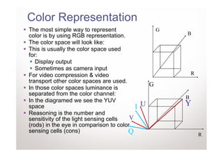
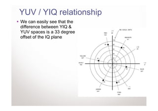
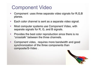
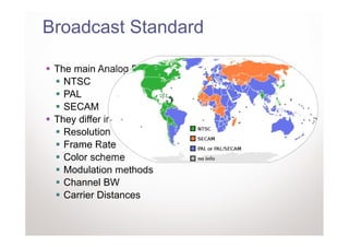
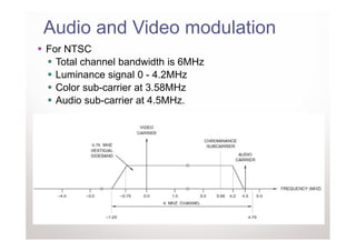
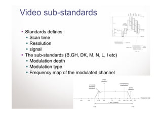
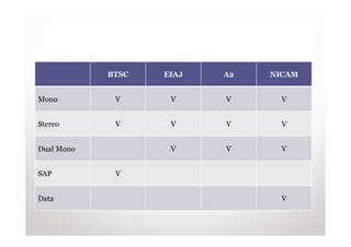
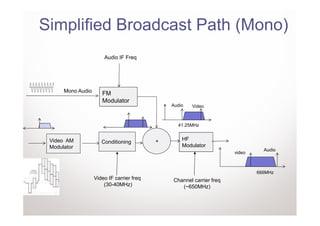
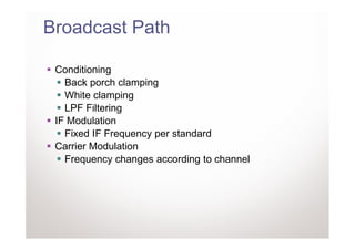
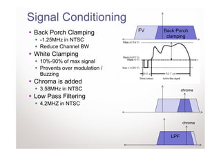
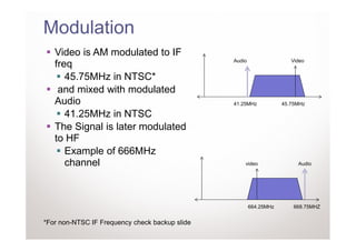
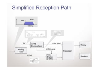

The document discusses analog video broadcast standards. It covers color spaces used in video like RGB, YUV, and YIQ. It then discusses analog TV connectors like composite video, S-video, and component video. The main sections of the document cover broadcast standards for NTSC, PAL, and SECAM as well as audio standards like BTSC, EIAJ, A2, and NICAM. It provides details on color modulation methods, transmission paths, and signal conditioning used in analog video broadcast.