Download to read offline

![TRAINING REPORT
Dept. Of ECE, VJCET 11
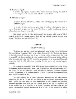
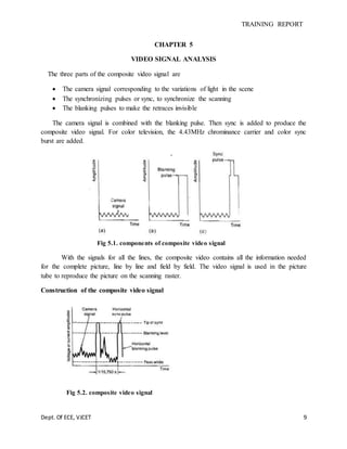
Composite video signal
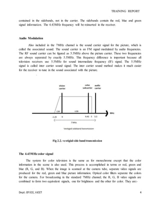
The standard composite video input or output signal has negative pulses and a level of 1
volt peak to peak [0.7V video + 0.3V sync]
Fig 5.5 composite video signal
CHAPTER 6
DIGITAL COMPRESSION
Digital television broadcasting has to happen, because service providers can no longer
afford the limitations of traditional analog transmission. The broadcaster has to find a more
spectrum efficient technology. One of the fundamentals of efficient use of spectrum is
compression is a way of expressing digital audio & video by using less data. Compression theory
suggests that the more effective the reduction in bandwidth has to be, the more complex signal
processing at lower cost than for broadcasting using the analog techniques.
The active region of a digital television frame, sampled according to CCIR
recommendation 601, is 702 pixels by 576 lines for a frame rate of 25 HZ using, 8 bit for
luminance & for chrominance component, and the compressed bit rates become in 4:2:2.
Using the various compression techniques these can be being down to 3-15 M bits. For
digital broadcasting of standard definition video, a bit rate of around 6 M bits is thought to be
good compromise between picture quality and transmission bandwidth efficiency. At the lower
bit rates in this range, the impairments introduced by coding and decoding process become
increasingly objectionable.](https://image.slidesharecdn.com/d1efe402-15d4-4857-a9b5-1f2720ea13ce-150906091126-lva1-app6892/85/TRAINING-REPORT-11-320.jpg)


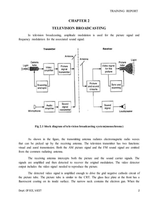
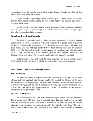
This document provides an overview of television broadcasting and color television signals. It discusses: 1) How a television system works, including converting images/sounds to electrical signals for transmission and reconversion to images/sounds at the receiver. 2) The process of television broadcasting, including using AM for video and FM for audio transmission within a 7MHz channel. 3) Details of video modulation, including vestigial sideband transmission and chrominance modulation. 4) The development of color television standards including the NTSC system which transmits a luminance signal and chrominance signal containing color information via a 4.43MHz subcarrier.