Download to read offline
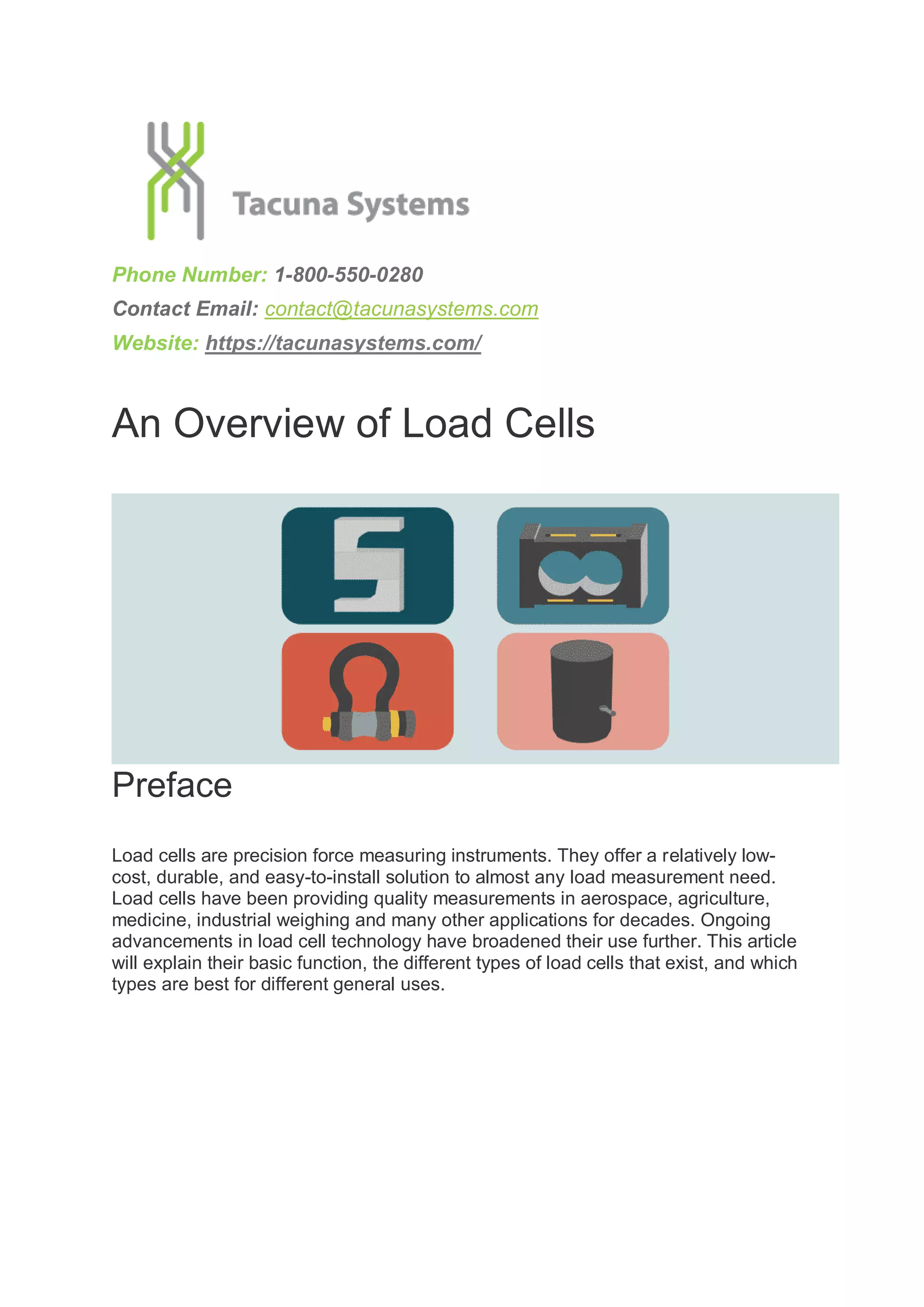
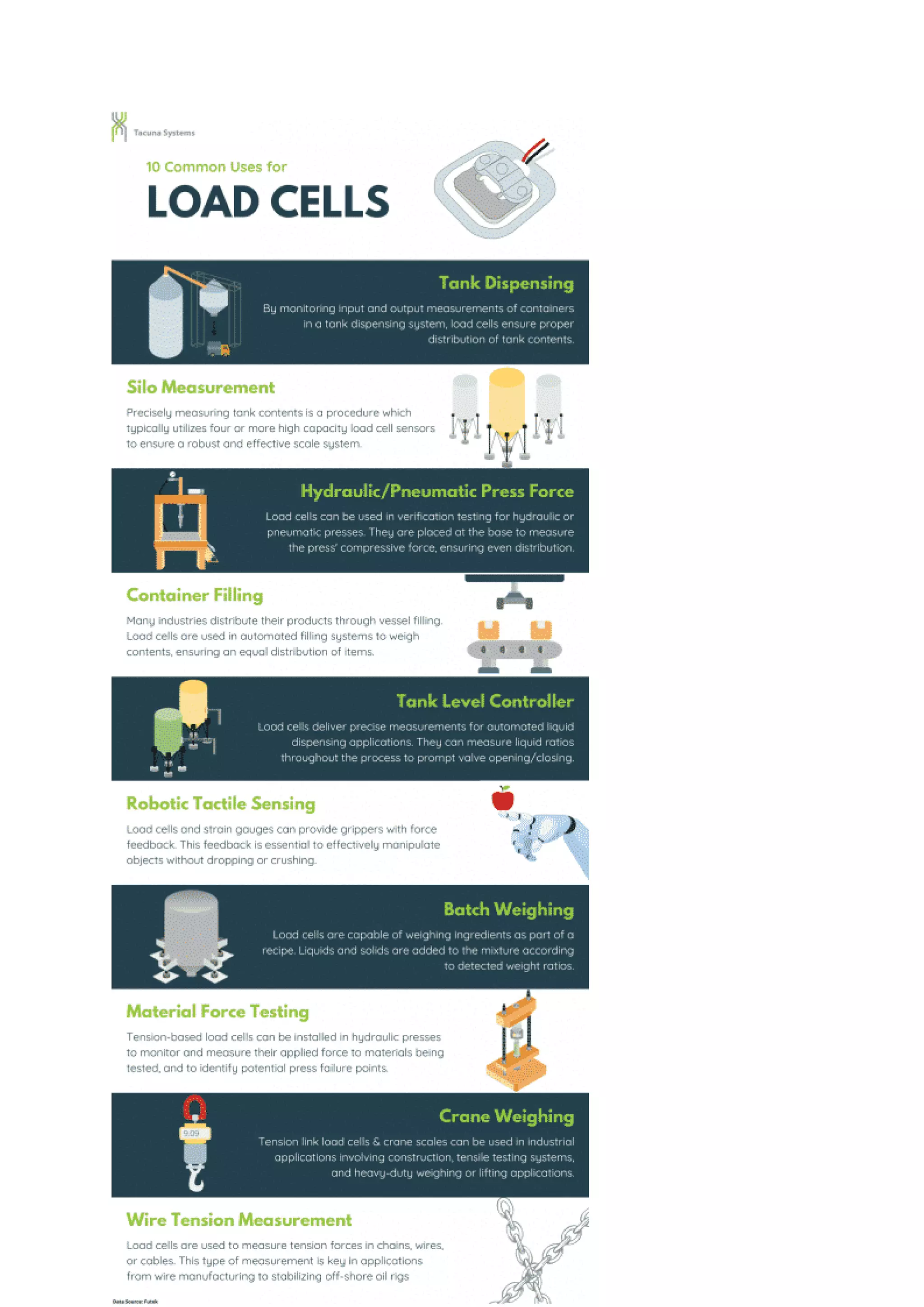


Load cells are precision force measuring instruments that convert applied forces into measurable electrical signals. There are several main types of load cells - strain gauge, hydraulic, pneumatic, capacitive, and piezoelectric - each with their own components, operating principles, benefits, and applications. Strain gauge load cells are the most common type and function by measuring the change in electrical resistance of strain gauges attached to a loading element under force. Load cells are widely used in industrial weighing, testing, process control, and other applications requiring accurate force or load measurement.