Download to read offline
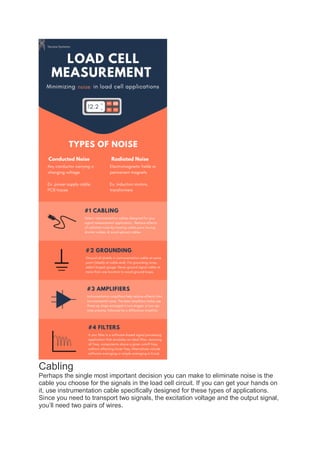

This document outlines best practices for reducing noise in sensitive load cell applications, emphasizing the importance of cable selection, grounding, and the use of instrumentation amplifiers. It discusses types of noise, specifically conducted and radiated noise, and provides recommendations for minimizing their impact through proper configuration and shielding. It concludes that while noise is unavoidable, strategic techniques can significantly enhance measurement accuracy.