Download to read offline
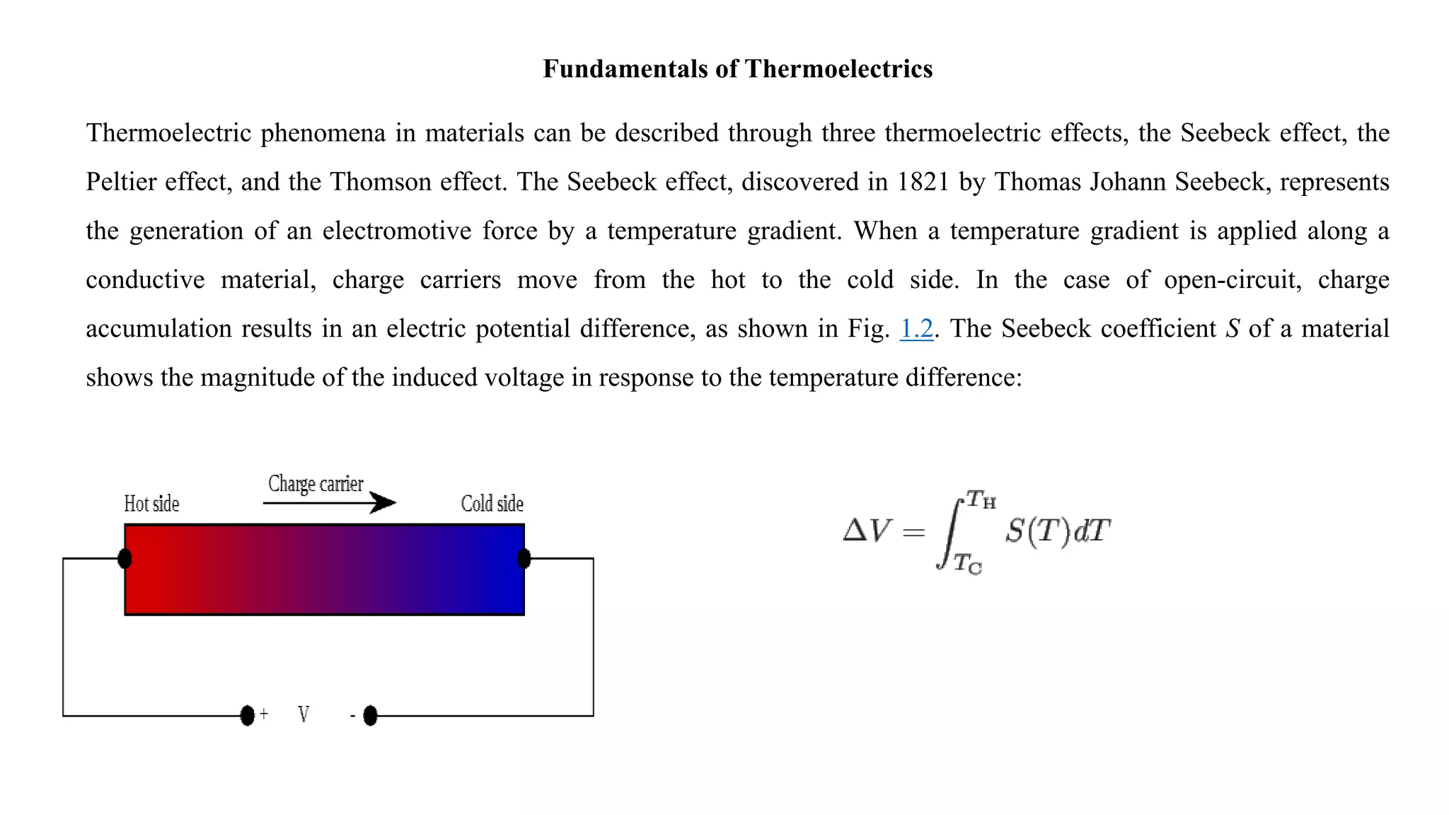
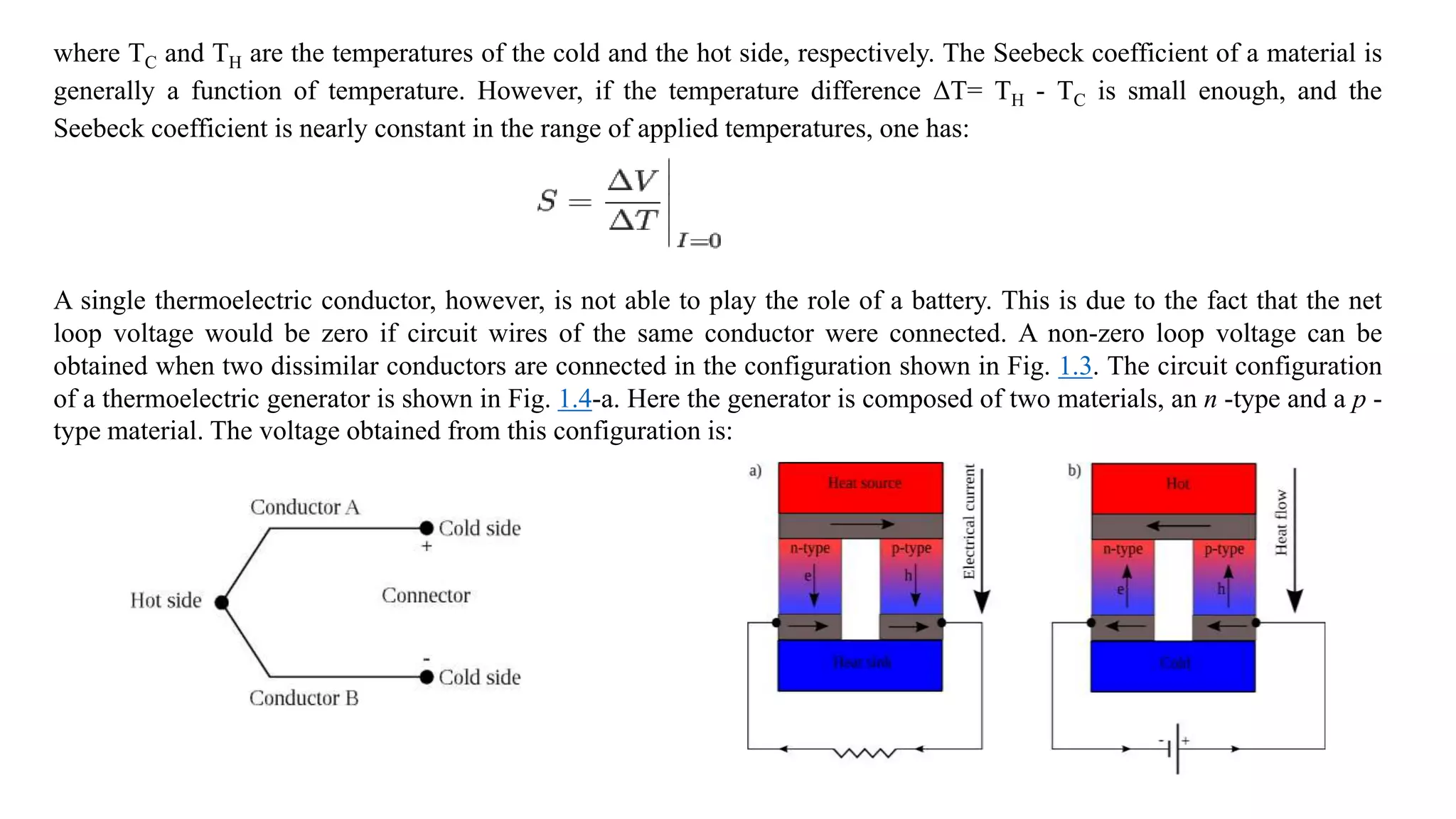
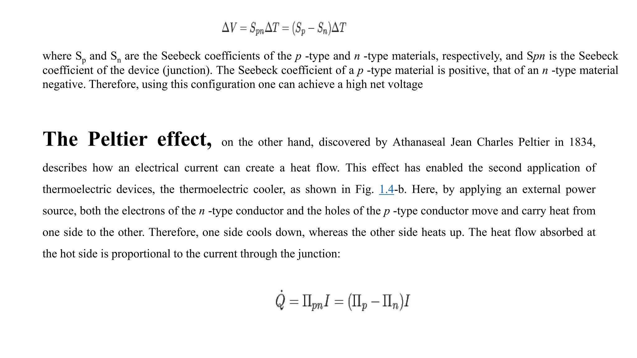
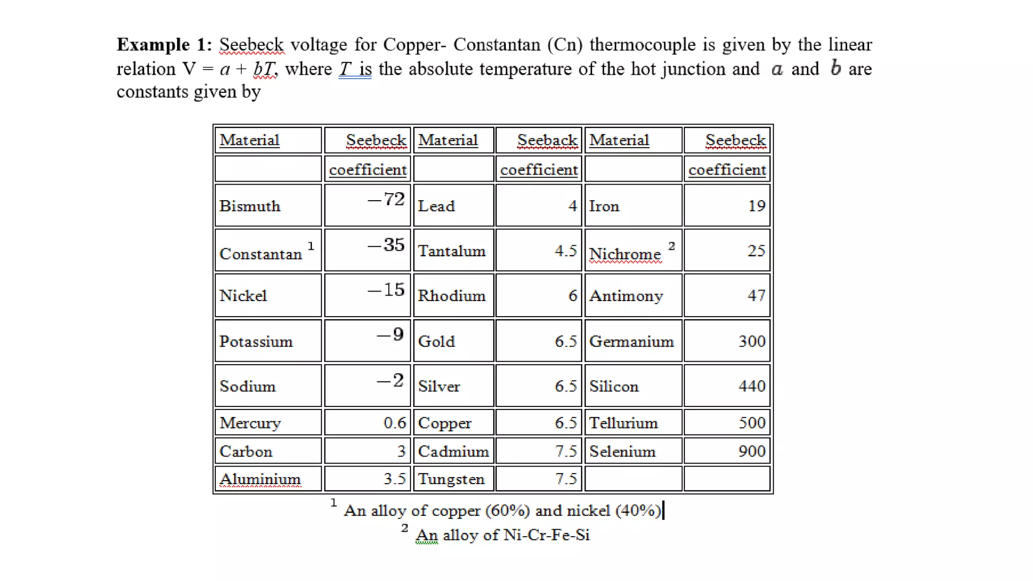
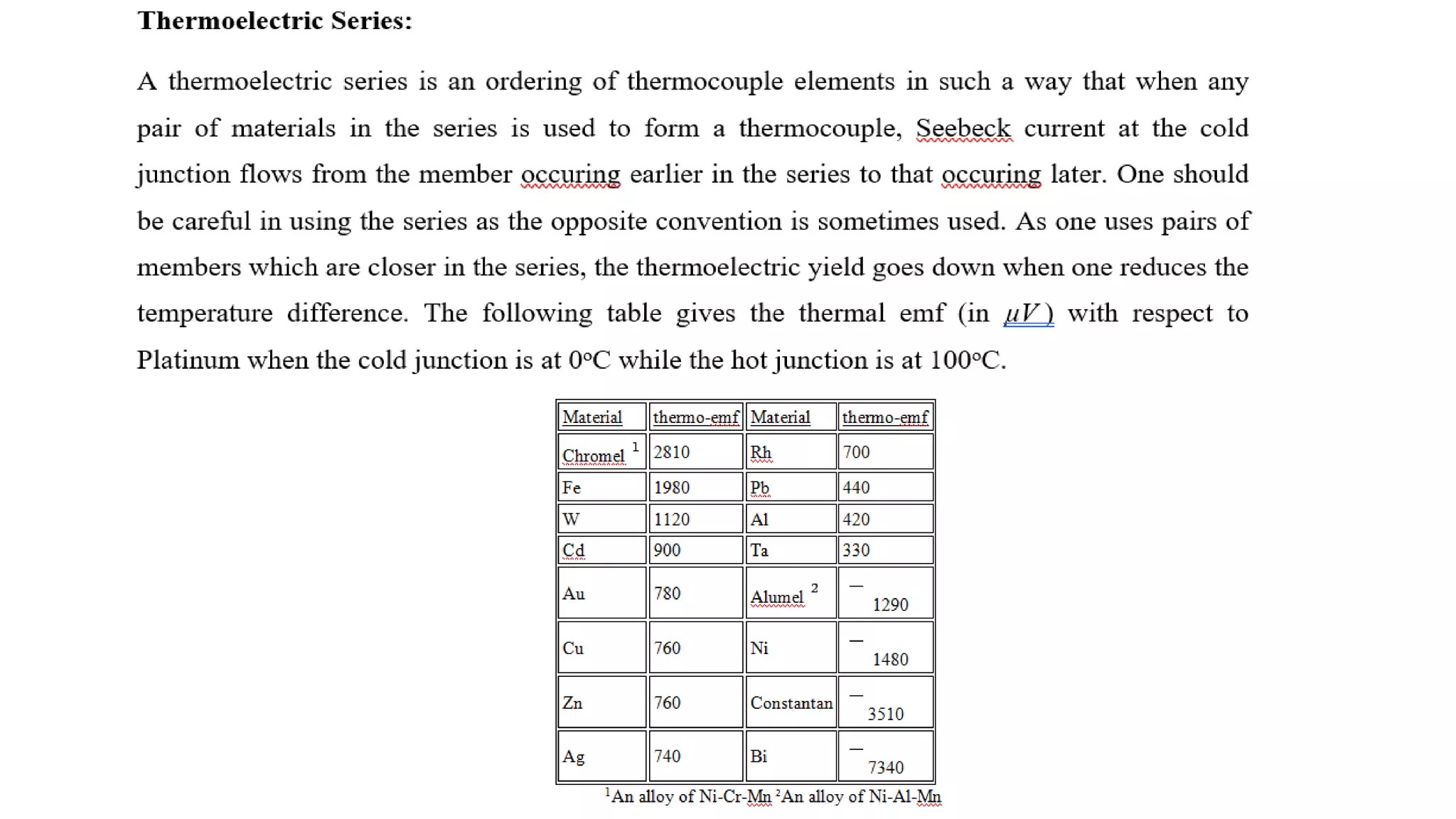
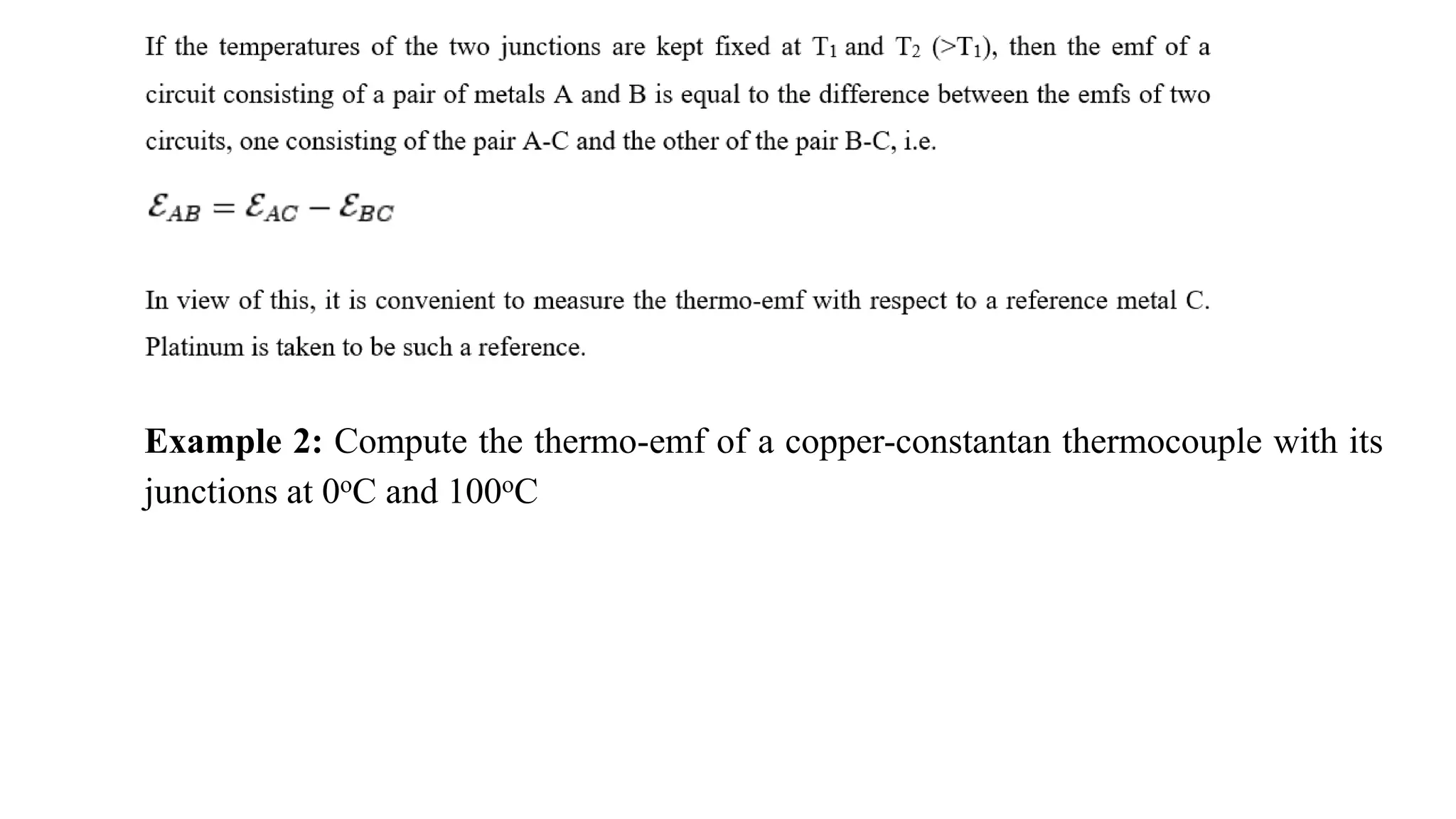

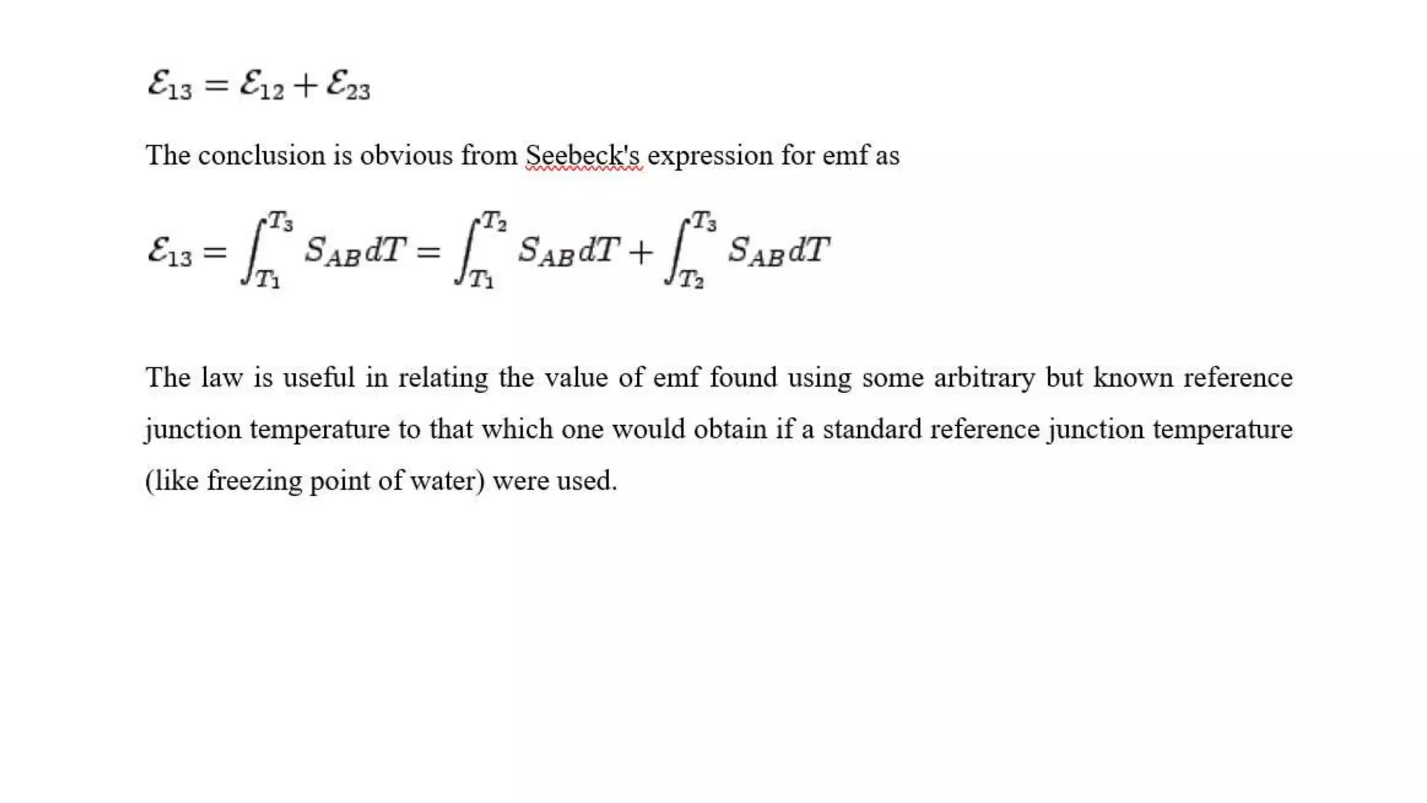

The document provides comprehensive information on alternating current (AC) and thermoelectricity, detailing definitions and expressions of RMS and average values, sinusoidal wave representation, circuit responses, resonance conditions, and the Maxwell bridge for inductance measurement. It also covers thermoelectric phenomena including the Seebeck, Peltier, and Thomson effects, their coefficients, and practical applications in thermoelectric circuits. Additionally, calculations related to circuit quality factors, bandwidth, and thermoelectric power are presented, alongside experimental setups for measuring thermoelectric effects.


![AC_CIRCUITS[1].pptx](https://cdn.slidesharecdn.com/ss_thumbnails/accircuits1-230813170350-dc7f310b-thumbnail.jpg?width=640&height=640&fit=bounds)