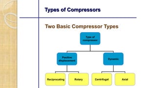
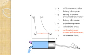
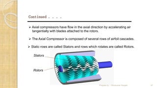
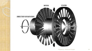
Introduction
A compressor is a machine capable of compressing and delivering
the air at desires pressure.
It is driven by a prime mover(Engine or a electric motor).
A compressor takes in atmospheric air, compresses it and delivers
the high pressure air to a receiver(storage vessel) from which it may
be conveyed by a pipeline.
Applications of compressed air
 For operating pneumatic hand tools such as rivet sets,
drills.
 painting and spraying.
 For driving mining tools.
 To supply the air blast in bessemer converter and blast
furnace.
 To operate air brakes in automobiles , ram lifts and
pneumatic conveyers.
 To supercharge IC Engines
 To inflate automobile tiers.
 To transmit power for operation of machines.
 To clean machines and work shop floor.
Two Basic Compressor Types
Types of Compressors
Type of
compressor
Positive
displacement
Dynamic
Reciprocating Rotary Centrifugal Axial
• Intake air filters
• Inter-stage coolers
• After coolers
• Air dryers
• Moisture drain traps
• Receivers
Main Components in Compressed
Air Systems
Introduction
Positive displacement compressor
 In the positive-displacement type, a given quantity of
air or gas is trapped in a compression chamber and
the volume it occupies is mechanically reduced,
causing a corresponding rise in pressure prior to
discharge. At constant speed, the air flow remains
essentially constant with variations in discharge
pressure.
Ex: Reciprocating compressors, screw compressors,
vane compressors & so on.
Prepare by :- Shivkumar Panjabi 7
Dynamic compressors:
 Dynamic compressors impart velocity energy to continuously
flowing air or gas by means of impellers rotating at very high
speeds. The velocity energy is changed into pressure energy
both by the impellers and the discharge volutes or diffusers. In
the centrifugal-type dynamic compressors, the shape of the
impeller blades determines the relationship between air flow
and the pressure (or head) generate.
Ex: centrifugal compressors, axial compressors.
Prepare by :- Shivkumar Panjabi 8
Reciprocating compressors
Principle of Operation
 Fig shows single-acting piston actions in the cylinder
of a reciprocating compressor.
 The piston is driven by a crank shaft via a connecting
rod.
 At the top of the cylinder are a suction valve and a
discharge valve.
 A reciprocating compressor usually has two, three,
four, or six cylinders in it.
9
Working principle of reciprocating air compressor
1 – 2 polytropic compression
(2 delivery valve opens)
2 – 3 delivery at constant
pressure and temperature
(3 delivery valve closes)
3 – 4 polytropic expansion
(4 suction valve opens)
4 – 1 suction at constant
pressure and temperature
(1 suction valve closes)
p
V
1
23
4
1 – 2 polytropic compression
(2 delivery valve opens)
2 – 3 delivery at constant
pressure and temperature
(3 delivery valve closes)
3 – 4 polytropic expansion
(4 suction valve opens)
4 – 1 suction at constant
pressure and temperature
(1 suction valve closes)
p
V
1
23
4
1 – 2 polytropic compression
(2 delivery valve opens)
2 – 3 delivery at constant
pressure and temperature
(3 delivery valve closes)
3 – 4 polytropic expansion
(4 suction valve opens)
4 – 1 suction at constant
pressure and temperature
(1 suction valve closes)
p
V
1
23
4
1 – 2 polytropic compression
(2 delivery valve opens)
2 – 3 delivery at constant
pressure and temperature
(3 delivery valve closes)
3 – 4 polytropic expansion
(4 suction valve opens)
4 – 1 suction at constant
pressure and temperature
(1 suction valve closes)
p
V
1
23
4
1 – 2 polytropic compression
(2 delivery valve opens)
2 – 3 delivery at constant
pressure and temperature
(3 delivery valve closes)
3 – 4 polytropic expansion
(4 suction valve opens)
4 – 1 suction at constant
pressure and temperature
(1 suction valve closes)
p
V
1
23
4
1 – 2 polytropic compression
(2 delivery valve opens)
2 – 3 delivery at constant
pressure and temperature
(3 delivery valve closes)
3 – 4 polytropic expansion
(4 suction valve opens)
4 – 1 suction at constant
pressure and temperature
(1 suction valve closes)
V
p
V
1
23
4
1 – 2 polytropic compression
(2 delivery valve opens)
2 – 3 delivery at constant
pressure and temperature
(3 delivery valve closes)
3 – 4 polytropic expansion
(4 suction valve opens)
4 – 1 suction at constant
pressure and temperature
(1 suction valve closes)
p
V
1
23
4
1 – 2 polytropic compression
(2 delivery valve opens)
2 – 3 delivery at constant
pressure and temperature
(3 delivery valve closes)
3 – 4 polytropic expansion
(4 suction valve opens)
4 – 1 suction at constant
pressure and temperature
(1 suction valve closes)
p
V
1
23
4
1 – 2 polytropic compression
(2 delivery valve opens)
2 – 3 delivery at constant
pressure and temperature
(3 delivery valve closes)
3 – 4 polytropic expansion
(4 suction valve opens)
4 – 1 suction at constant
pressure and temperature
(1 suction valve closes)
p
V
1
23
4
p
V
1
23
4
1 – 2 polytropic compression
(2 delivery valve opens)
2 – 3 delivery at constant
pressure and temperature
(3 delivery valve closes)
3 – 4 polytropic expansion
(4 suction valve opens)
4 – 1 suction at constant
pressure and temperature
(1 suction valve closes)
1 – 2 polytropic compression
(2 delivery valve opens)
2 – 3 delivery at constant
pressure and temperature
(3 delivery valve closes)
3 – 4 polytropic expansion
(4 suction valve opens)
4 – 1 suction at constant
pressure and temperature
(1 suction valve closes)
p
V
1
23
4
1 – 2 polytropic compression
(2 delivery valve opens)
2 – 3 delivery at constant
pressure and temperature
(3 delivery valve closes)
3 – 4 polytropic expansion
(4 suction valve opens)
4 – 1 suction at constant
pressure and temperature
(1 suction valve closes)
p
V
1
23
4
1 – 2 polytropic compression
(2 delivery valve opens)
2 – 3 delivery at constant
pressure and temperature
(3 delivery valve closes)
3 – 4 polytropic expansion
(4 suction valve opens)
4 – 1 suction at constant
pressure and temperature
(1 suction valve closes)
p
V
1
23
4
1 – 2 polytropic compression
(2 delivery valve opens)
2 – 3 delivery at constant
pressure and temperature
(3 delivery valve closes)
3 – 4 polytropic expansion
(4 suction valve opens)
4 – 1 suction at constant
pressure and temperature
(1 suction valve closes)
p
V
1
23
4
1 – 2 polytropic compression
(2 delivery valve opens)
2 – 3 delivery at constant
pressure and temperature
(3 delivery valve closes)
3 – 4 polytropic expansion
(4 suction valve opens)
4 – 1 suction at constant
pressure and temperature
(1 suction valve closes)
p
V
1
23
4
1 – 2 polytropic compression
(2 delivery valve opens)
2 – 3 delivery at constant
pressure and temperature
(3 delivery valve closes)
3 – 4 polytropic expansion
(4 suction valve opens)
4 – 1 suction at constant
pressure and temperature
(1 suction valve closes)
p
V
1
23
4
1 – 2 polytropic compression
(2 delivery valve opens)
2 – 3 delivery at constant
pressure and temperature
(3 delivery valve closes)
3 – 4 polytropic expansion
(4 suction valve opens)
4 – 1 suction at constant
pressure and temperature
(1 suction valve closes)
p
V
1
23
4
1 – 2 polytropic compression
(2 delivery valve opens)
2 – 3 delivery at constant
pressure and temperature
(3 delivery valve closes)
3 – 4 polytropic expansion
(4 suction valve opens)
4 – 1 suction at constant
pressure and temperature
(1 suction valve closes)
p
V
1
23
4
1 – 2 polytropic compression
(2 delivery valve opens)
2 – 3 delivery at constant
pressure and temperature
(3 delivery valve closes)
3 – 4 polytropic expansion
(4 suction valve opens)
4 – 1 suction at constant
pressure and temperature
(1 suction valve closes)
p
V
1
23
4
1 – 2 polytropic compression
(2 delivery valve opens)
2 – 3 delivery at constant
pressure and temperature
(3 delivery valve closes)
3 – 4 polytropic expansion
(4 suction valve opens)
4 – 1 suction at constant
pressure and temperature
(1 suction valve closes)
p
V
1
23
4
1 – 2 polytropic compression
(2 delivery valve opens)
2 – 3 delivery at constant
pressure and temperature
(3 delivery valve closes)
3 – 4 polytropic expansion
(4 suction valve opens)
4 – 1 suction at constant
pressure and temperature
(1 suction valve closes)
p
V
1
23
4
1 – 2 polytropic compression
(2 delivery valve opens)
2 – 3 delivery at constant
pressure and temperature
(3 delivery valve closes)
3 – 4 polytropic expansion
(4 suction valve opens)
4 – 1 suction at constant
pressure and temperature
(1 suction valve closes)
p
V
1
23
4
1 – 2 polytropic compression
(2 delivery valve opens)
2 – 3 delivery at constant
pressure and temperature
(3 delivery valve closes)
3 – 4 polytropic expansion
(4 suction valve opens)
4 – 1 suction at constant
pressure and temperature
(1 suction valve closes)
p
V
1
23
4
1 – 2 polytropic compression
(2 delivery valve opens)
2 – 3 delivery at constant
pressure and temperature
(3 delivery valve closes)
3 – 4 polytropic expansion
(4 suction valve opens)
4 – 1 suction at constant
pressure and temperature
(1 suction valve closes)
p
V
1
23
4
1 – 2 polytropic compression
(2 delivery valve opens)
2 – 3 delivery at constant
pressure and temperature
(3 delivery valve closes)
3 – 4 polytropic expansion
(4 suction valve opens)
4 – 1 suction at constant
pressure and temperature
(1 suction valve closes)
p
V
1
23
4
1 – 2 polytropic compression
(2 delivery valve opens)
2 – 3 delivery at constant
pressure and temperature
(3 delivery valve closes)
3 – 4 polytropic expansion
(4 suction valve opens)
4 – 1 suction at constant
pressure and temperature
(1 suction valve closes)
p
V
1
23
4
1 – 2 polytropic compression
(2 delivery valve opens)
2 – 3 delivery at constant
pressure and temperature
(3 delivery valve closes)
3 – 4 polytropic expansion
(4 suction valve opens)
4 – 1 suction at constant
pressure and temperature
(1 suction valve closes)
p
V
1
23
4
Reciprocating Compressor: Ideal Indicator Diagram
1 – 2 polytropic compression
(2 delivery valve opens)
2 – 3 delivery at constant
pressure and temperature
(3 delivery valve closes)
3 – 4 polytrophic expansion
(4 suction valve opens)
4 – 1 suction at constant
pressure and temperature
(1 suction valve closes)
p
V
1
23
4
Multistage Reciprocating
Compressors
The compression of air in single stage has
many disadvantages and its use is limited
where low delivery pressure is required.
A multistage compression is more efficient
and mostly employed for high pressures.
Line Diagram of a Reciprocating
Compressor
Cross Section of a multi stage
compressor
Advantages of multistage compression
It provides a facility to install an inter cooler between
the stages.
Less power is required to deliver the same quantity
of air at the same delivery pressure.
Better lubrication due to lower temperature.
Centrifugal compressors
 The centrifugal air compressor is a dynamic
compressor, which depends on transfer of
energy from a rotating impeller to the air. The
rotor accomplishes this by changing the
momentum and pressure of the air. This
momentum is converted to useful pressure by
slowing the air down in a stationary diffuser.
43
Centrifugal compressors
44
Centrifugal compressors
AXIAL COMPRESSORS
 Axial flow compressors are designed for high volume, high efficiency
and high reliability applications.
Typical applications of Axial Compressors are air separation, sewage
treatment, wind tunnel, FCC air blowers, Blast furnaces etc.
 Now a days commonly used in Aeroplanes.
46
Continued . . . .
 Axial compressors have flow in the axial direction by accelerating air
tangentially with blades attached to the rotors.
 The Axial Compressor is composed of several rows of airfoil cascades.
 Static rows are called Stators and rows which rotates are called Rotors.
Rotors
Stators
Prepare by :- Shivkumar Panjabi 47
Prepare by :- Shivkumar Panjabi 48
Rotary Compressors
Rotary compressors are broadly classified into two types.
1.Positive displacement compressor.
a) Vane compressor
b) Roots blower
c) Screw compressor
2. Non Positive Displacement(study flow) compressors
a) Radial Centrifugal compressor
b) Axial Flow Compressor
Rotary vane compressors
 Rotary vane compressors consist of a rotor
with a number of blades inserted in radial slots
in the rotor. The rotor is mounted offset in a
larger housing that is either circular or a more
complex shape. As the rotor turns, blades slide
in and out of the slots keeping contact with the
outer wall of the housing. Thus, a series of
decreasing volumes is created by the rotating
blades.
Prepare by :- Shivkumar Panjabi 50
Vane Compressor
Prepare by :- Shivkumar Panjabi 51
Prepare by :- Shivkumar Panjabi 52
Roots Blower
Its consists of two rotors each having two
lobes and are enclosed in a casing.
Two rotors are driven by a pair of equal spur
gears.
As the rotor rotates further air is trapped
between the rotors and the casing.
This air is transferred to the delivery side at
constant pressure.
Prepare by :- Shivkumar Panjabi 54
Screw Compressors
 Rotary screw compressors are also positive
displacement machines.
 These compressors employ two rotating interleaved
helical screws which capture air in a pocket between
them
 The space in which the air is trapped becomes
smaller as it moves down the axis of the screw.
 Finally compressed air discharge from the opposite
end of intake.
Screw Compressors
Thank you
for your
attention

Air Compressor in mechanical Engineering

  • 3.
    Introduction A compressor isa machine capable of compressing and delivering the air at desires pressure. It is driven by a prime mover(Engine or a electric motor). A compressor takes in atmospheric air, compresses it and delivers the high pressure air to a receiver(storage vessel) from which it may be conveyed by a pipeline.
  • 4.
    Applications of compressedair  For operating pneumatic hand tools such as rivet sets, drills.  painting and spraying.  For driving mining tools.  To supply the air blast in bessemer converter and blast furnace.  To operate air brakes in automobiles , ram lifts and pneumatic conveyers.  To supercharge IC Engines  To inflate automobile tiers.  To transmit power for operation of machines.  To clean machines and work shop floor.
  • 5.
    Two Basic CompressorTypes Types of Compressors Type of compressor Positive displacement Dynamic Reciprocating Rotary Centrifugal Axial
  • 6.
    • Intake airfilters • Inter-stage coolers • After coolers • Air dryers • Moisture drain traps • Receivers Main Components in Compressed Air Systems Introduction
  • 7.
    Positive displacement compressor In the positive-displacement type, a given quantity of air or gas is trapped in a compression chamber and the volume it occupies is mechanically reduced, causing a corresponding rise in pressure prior to discharge. At constant speed, the air flow remains essentially constant with variations in discharge pressure. Ex: Reciprocating compressors, screw compressors, vane compressors & so on. Prepare by :- Shivkumar Panjabi 7
  • 8.
    Dynamic compressors:  Dynamiccompressors impart velocity energy to continuously flowing air or gas by means of impellers rotating at very high speeds. The velocity energy is changed into pressure energy both by the impellers and the discharge volutes or diffusers. In the centrifugal-type dynamic compressors, the shape of the impeller blades determines the relationship between air flow and the pressure (or head) generate. Ex: centrifugal compressors, axial compressors. Prepare by :- Shivkumar Panjabi 8
  • 9.
    Reciprocating compressors Principle ofOperation  Fig shows single-acting piston actions in the cylinder of a reciprocating compressor.  The piston is driven by a crank shaft via a connecting rod.  At the top of the cylinder are a suction valve and a discharge valve.  A reciprocating compressor usually has two, three, four, or six cylinders in it. 9
  • 10.
    Working principle ofreciprocating air compressor
  • 11.
    1 – 2polytropic compression (2 delivery valve opens) 2 – 3 delivery at constant pressure and temperature (3 delivery valve closes) 3 – 4 polytropic expansion (4 suction valve opens) 4 – 1 suction at constant pressure and temperature (1 suction valve closes) p V 1 23 4
  • 12.
    1 – 2polytropic compression (2 delivery valve opens) 2 – 3 delivery at constant pressure and temperature (3 delivery valve closes) 3 – 4 polytropic expansion (4 suction valve opens) 4 – 1 suction at constant pressure and temperature (1 suction valve closes) p V 1 23 4
  • 13.
    1 – 2polytropic compression (2 delivery valve opens) 2 – 3 delivery at constant pressure and temperature (3 delivery valve closes) 3 – 4 polytropic expansion (4 suction valve opens) 4 – 1 suction at constant pressure and temperature (1 suction valve closes) p V 1 23 4
  • 14.
    1 – 2polytropic compression (2 delivery valve opens) 2 – 3 delivery at constant pressure and temperature (3 delivery valve closes) 3 – 4 polytropic expansion (4 suction valve opens) 4 – 1 suction at constant pressure and temperature (1 suction valve closes) p V 1 23 4
  • 15.
    1 – 2polytropic compression (2 delivery valve opens) 2 – 3 delivery at constant pressure and temperature (3 delivery valve closes) 3 – 4 polytropic expansion (4 suction valve opens) 4 – 1 suction at constant pressure and temperature (1 suction valve closes) p V 1 23 4
  • 16.
    1 – 2polytropic compression (2 delivery valve opens) 2 – 3 delivery at constant pressure and temperature (3 delivery valve closes) 3 – 4 polytropic expansion (4 suction valve opens) 4 – 1 suction at constant pressure and temperature (1 suction valve closes) V p V 1 23 4
  • 17.
    1 – 2polytropic compression (2 delivery valve opens) 2 – 3 delivery at constant pressure and temperature (3 delivery valve closes) 3 – 4 polytropic expansion (4 suction valve opens) 4 – 1 suction at constant pressure and temperature (1 suction valve closes) p V 1 23 4
  • 18.
    1 – 2polytropic compression (2 delivery valve opens) 2 – 3 delivery at constant pressure and temperature (3 delivery valve closes) 3 – 4 polytropic expansion (4 suction valve opens) 4 – 1 suction at constant pressure and temperature (1 suction valve closes) p V 1 23 4
  • 19.
    1 – 2polytropic compression (2 delivery valve opens) 2 – 3 delivery at constant pressure and temperature (3 delivery valve closes) 3 – 4 polytropic expansion (4 suction valve opens) 4 – 1 suction at constant pressure and temperature (1 suction valve closes) p V 1 23 4
  • 20.
    p V 1 23 4 1 – 2polytropic compression (2 delivery valve opens) 2 – 3 delivery at constant pressure and temperature (3 delivery valve closes) 3 – 4 polytropic expansion (4 suction valve opens) 4 – 1 suction at constant pressure and temperature (1 suction valve closes)
  • 21.
    1 – 2polytropic compression (2 delivery valve opens) 2 – 3 delivery at constant pressure and temperature (3 delivery valve closes) 3 – 4 polytropic expansion (4 suction valve opens) 4 – 1 suction at constant pressure and temperature (1 suction valve closes) p V 1 23 4
  • 22.
    1 – 2polytropic compression (2 delivery valve opens) 2 – 3 delivery at constant pressure and temperature (3 delivery valve closes) 3 – 4 polytropic expansion (4 suction valve opens) 4 – 1 suction at constant pressure and temperature (1 suction valve closes) p V 1 23 4
  • 23.
    1 – 2polytropic compression (2 delivery valve opens) 2 – 3 delivery at constant pressure and temperature (3 delivery valve closes) 3 – 4 polytropic expansion (4 suction valve opens) 4 – 1 suction at constant pressure and temperature (1 suction valve closes) p V 1 23 4
  • 24.
    1 – 2polytropic compression (2 delivery valve opens) 2 – 3 delivery at constant pressure and temperature (3 delivery valve closes) 3 – 4 polytropic expansion (4 suction valve opens) 4 – 1 suction at constant pressure and temperature (1 suction valve closes) p V 1 23 4
  • 25.
    1 – 2polytropic compression (2 delivery valve opens) 2 – 3 delivery at constant pressure and temperature (3 delivery valve closes) 3 – 4 polytropic expansion (4 suction valve opens) 4 – 1 suction at constant pressure and temperature (1 suction valve closes) p V 1 23 4
  • 26.
    1 – 2polytropic compression (2 delivery valve opens) 2 – 3 delivery at constant pressure and temperature (3 delivery valve closes) 3 – 4 polytropic expansion (4 suction valve opens) 4 – 1 suction at constant pressure and temperature (1 suction valve closes) p V 1 23 4
  • 27.
    1 – 2polytropic compression (2 delivery valve opens) 2 – 3 delivery at constant pressure and temperature (3 delivery valve closes) 3 – 4 polytropic expansion (4 suction valve opens) 4 – 1 suction at constant pressure and temperature (1 suction valve closes) p V 1 23 4
  • 28.
    1 – 2polytropic compression (2 delivery valve opens) 2 – 3 delivery at constant pressure and temperature (3 delivery valve closes) 3 – 4 polytropic expansion (4 suction valve opens) 4 – 1 suction at constant pressure and temperature (1 suction valve closes) p V 1 23 4
  • 29.
    1 – 2polytropic compression (2 delivery valve opens) 2 – 3 delivery at constant pressure and temperature (3 delivery valve closes) 3 – 4 polytropic expansion (4 suction valve opens) 4 – 1 suction at constant pressure and temperature (1 suction valve closes) p V 1 23 4
  • 30.
    1 – 2polytropic compression (2 delivery valve opens) 2 – 3 delivery at constant pressure and temperature (3 delivery valve closes) 3 – 4 polytropic expansion (4 suction valve opens) 4 – 1 suction at constant pressure and temperature (1 suction valve closes) p V 1 23 4
  • 31.
    1 – 2polytropic compression (2 delivery valve opens) 2 – 3 delivery at constant pressure and temperature (3 delivery valve closes) 3 – 4 polytropic expansion (4 suction valve opens) 4 – 1 suction at constant pressure and temperature (1 suction valve closes) p V 1 23 4
  • 32.
    1 – 2polytropic compression (2 delivery valve opens) 2 – 3 delivery at constant pressure and temperature (3 delivery valve closes) 3 – 4 polytropic expansion (4 suction valve opens) 4 – 1 suction at constant pressure and temperature (1 suction valve closes) p V 1 23 4
  • 33.
    1 – 2polytropic compression (2 delivery valve opens) 2 – 3 delivery at constant pressure and temperature (3 delivery valve closes) 3 – 4 polytropic expansion (4 suction valve opens) 4 – 1 suction at constant pressure and temperature (1 suction valve closes) p V 1 23 4
  • 34.
    1 – 2polytropic compression (2 delivery valve opens) 2 – 3 delivery at constant pressure and temperature (3 delivery valve closes) 3 – 4 polytropic expansion (4 suction valve opens) 4 – 1 suction at constant pressure and temperature (1 suction valve closes) p V 1 23 4
  • 35.
    1 – 2polytropic compression (2 delivery valve opens) 2 – 3 delivery at constant pressure and temperature (3 delivery valve closes) 3 – 4 polytropic expansion (4 suction valve opens) 4 – 1 suction at constant pressure and temperature (1 suction valve closes) p V 1 23 4
  • 36.
    1 – 2polytropic compression (2 delivery valve opens) 2 – 3 delivery at constant pressure and temperature (3 delivery valve closes) 3 – 4 polytropic expansion (4 suction valve opens) 4 – 1 suction at constant pressure and temperature (1 suction valve closes) p V 1 23 4
  • 37.
    1 – 2polytropic compression (2 delivery valve opens) 2 – 3 delivery at constant pressure and temperature (3 delivery valve closes) 3 – 4 polytropic expansion (4 suction valve opens) 4 – 1 suction at constant pressure and temperature (1 suction valve closes) p V 1 23 4
  • 38.
    Reciprocating Compressor: IdealIndicator Diagram 1 – 2 polytropic compression (2 delivery valve opens) 2 – 3 delivery at constant pressure and temperature (3 delivery valve closes) 3 – 4 polytrophic expansion (4 suction valve opens) 4 – 1 suction at constant pressure and temperature (1 suction valve closes) p V 1 23 4
  • 39.
    Multistage Reciprocating Compressors The compressionof air in single stage has many disadvantages and its use is limited where low delivery pressure is required. A multistage compression is more efficient and mostly employed for high pressures.
  • 40.
    Line Diagram ofa Reciprocating Compressor
  • 41.
    Cross Section ofa multi stage compressor
  • 42.
    Advantages of multistagecompression It provides a facility to install an inter cooler between the stages. Less power is required to deliver the same quantity of air at the same delivery pressure. Better lubrication due to lower temperature.
  • 43.
    Centrifugal compressors  Thecentrifugal air compressor is a dynamic compressor, which depends on transfer of energy from a rotating impeller to the air. The rotor accomplishes this by changing the momentum and pressure of the air. This momentum is converted to useful pressure by slowing the air down in a stationary diffuser. 43
  • 44.
  • 45.
  • 46.
    AXIAL COMPRESSORS  Axialflow compressors are designed for high volume, high efficiency and high reliability applications. Typical applications of Axial Compressors are air separation, sewage treatment, wind tunnel, FCC air blowers, Blast furnaces etc.  Now a days commonly used in Aeroplanes. 46
  • 47.
    Continued . .. .  Axial compressors have flow in the axial direction by accelerating air tangentially with blades attached to the rotors.  The Axial Compressor is composed of several rows of airfoil cascades.  Static rows are called Stators and rows which rotates are called Rotors. Rotors Stators Prepare by :- Shivkumar Panjabi 47
  • 48.
    Prepare by :-Shivkumar Panjabi 48
  • 49.
    Rotary Compressors Rotary compressorsare broadly classified into two types. 1.Positive displacement compressor. a) Vane compressor b) Roots blower c) Screw compressor 2. Non Positive Displacement(study flow) compressors a) Radial Centrifugal compressor b) Axial Flow Compressor
  • 50.
    Rotary vane compressors Rotary vane compressors consist of a rotor with a number of blades inserted in radial slots in the rotor. The rotor is mounted offset in a larger housing that is either circular or a more complex shape. As the rotor turns, blades slide in and out of the slots keeping contact with the outer wall of the housing. Thus, a series of decreasing volumes is created by the rotating blades. Prepare by :- Shivkumar Panjabi 50
  • 51.
    Vane Compressor Prepare by:- Shivkumar Panjabi 51
  • 52.
    Prepare by :-Shivkumar Panjabi 52
  • 53.
    Roots Blower Its consistsof two rotors each having two lobes and are enclosed in a casing. Two rotors are driven by a pair of equal spur gears. As the rotor rotates further air is trapped between the rotors and the casing. This air is transferred to the delivery side at constant pressure.
  • 54.
    Prepare by :-Shivkumar Panjabi 54
  • 55.
    Screw Compressors  Rotaryscrew compressors are also positive displacement machines.  These compressors employ two rotating interleaved helical screws which capture air in a pocket between them  The space in which the air is trapped becomes smaller as it moves down the axis of the screw.  Finally compressed air discharge from the opposite end of intake.
  • 56.
  • 57.