An air brake system uses compressed air to apply pressure to brake pads to stop vehicles. George Westinghouse first developed air brakes for railroads in the late 1800s. In the early 1900s, air brakes were adopted for use in trucks and other heavy road vehicles due to their reliability. An air brake system has several components including an air compressor, air reservoirs, a foot valve, brake chambers, and brake linings or rotors. The compressor pumps compressed air into reservoirs, which is then applied to the brakes via the foot valve and chambers when stopping is needed. Air brakes are advantageous for heavy vehicles due to their reliability and ability to stop even with leaks, but do require more training and maintenance than hydraulic bra
The suspension System of an automobile is one which separates the wheel/axle assembly from the body. The primary function of the suspension system is to isolate the vehicle structure from shocks & vibration due to irregularities of the road surface.
This slides are about inline injection pump and calibration of the pumps .The working of the pump is described in simple words and with examples of daily usable devices.
Air braking in Heavy Commercial Vehicles (HCV)Deepak Kumar
A detailed presentation on the topic "Air braking in heavy commercial vehicles (HCVs)". The ppt contains working and technical details of Air Braking System. Main components like Air Compressor, Reservoir, Unloader Valve, Brake Valve, Brake Chamber, Quick Release Valve and Relay Valve has been explained in details in this ppt.
This presentation include the information about the different types of superchargers, advantages & disadvantages of superchargers and turbochargers. One case study of variable geometry turbocharger is included with literature review.
Introduction : Basic Feature of an Automobile
Car Body Details
Types of Vehicle
Body Engineering Terminology
Morphology of Vehicle Body ( Structural ) Design
Design Considerations
The aim is to design and to develop an air brake system based on exhaust gas is called “fabrication of air brake system using engine exhaust gas”. The main aim of this project is to reduce the workloads of the engine drive to operate the air compressor, because here the compressor is not operated by the engine drive.
Here we are placing a turbine in the path of exhaust from the engine. The turbine e is connected to a dynamo by means of coupling, which is used to generate power. Depending upon the airflow the turbine will start rotating, and then the dynamo will also starts to rotate. A dynamo is a device which is used to convert the kinetic energy into electrical energy. The generated power can be stored in the battery and then this electric power has loaded to the D.C compressor. The air compressor compresses the atmospheric air and it stored in the air tank and the air tank has pressure relief valve to control the pressure in the tank . The air tank supplies the compressed pneumatic power to the pneumatic actuator through solenoid valve to apply brake. The pneumatic actuator is a double acting cylinder which converts hydraulic energy into linear moti on.
Democratizing Fuzzing at Scale by Abhishek Aryaabh.arya
Presented at NUS: Fuzzing and Software Security Summer School 2024
This keynote talks about the democratization of fuzzing at scale, highlighting the collaboration between open source communities, academia, and industry to advance the field of fuzzing. It delves into the history of fuzzing, the development of scalable fuzzing platforms, and the empowerment of community-driven research. The talk will further discuss recent advancements leveraging AI/ML and offer insights into the future evolution of the fuzzing landscape.
Forklift Classes Overview by Intella PartsIntella Parts
Discover the different forklift classes and their specific applications. Learn how to choose the right forklift for your needs to ensure safety, efficiency, and compliance in your operations.
For more technical information, visit our website https://intellaparts.com
Explore the innovative world of trenchless pipe repair with our comprehensive guide, "The Benefits and Techniques of Trenchless Pipe Repair." This document delves into the modern methods of repairing underground pipes without the need for extensive excavation, highlighting the numerous advantages and the latest techniques used in the industry.
Learn about the cost savings, reduced environmental impact, and minimal disruption associated with trenchless technology. Discover detailed explanations of popular techniques such as pipe bursting, cured-in-place pipe (CIPP) lining, and directional drilling. Understand how these methods can be applied to various types of infrastructure, from residential plumbing to large-scale municipal systems.
Ideal for homeowners, contractors, engineers, and anyone interested in modern plumbing solutions, this guide provides valuable insights into why trenchless pipe repair is becoming the preferred choice for pipe rehabilitation. Stay informed about the latest advancements and best practices in the field.
Final project report on grocery store management system..pdfKamal Acharya
In today’s fast-changing business environment, it’s extremely important to be able to respond to client needs in the most effective and timely manner. If your customers wish to see your business online and have instant access to your products or services.
Online Grocery Store is an e-commerce website, which retails various grocery products. This project allows viewing various products available enables registered users to purchase desired products instantly using Paytm, UPI payment processor (Instant Pay) and also can place order by using Cash on Delivery (Pay Later) option. This project provides an easy access to Administrators and Managers to view orders placed using Pay Later and Instant Pay options.
In order to develop an e-commerce website, a number of Technologies must be studied and understood. These include multi-tiered architecture, server and client-side scripting techniques, implementation technologies, programming language (such as PHP, HTML, CSS, JavaScript) and MySQL relational databases. This is a project with the objective to develop a basic website where a consumer is provided with a shopping cart website and also to know about the technologies used to develop such a website.
This document will discuss each of the underlying technologies to create and implement an e- commerce website.
TECHNICAL TRAINING MANUAL GENERAL FAMILIARIZATION COURSEDuvanRamosGarzon1
AIRCRAFT GENERAL
The Single Aisle is the most advanced family aircraft in service today, with fly-by-wire flight controls.
The A318, A319, A320 and A321 are twin-engine subsonic medium range aircraft.
The family offers a choice of engines
Courier management system project report.pdfKamal Acharya
It is now-a-days very important for the people to send or receive articles like imported furniture, electronic items, gifts, business goods and the like. People depend vastly on different transport systems which mostly use the manual way of receiving and delivering the articles. There is no way to track the articles till they are received and there is no way to let the customer know what happened in transit, once he booked some articles. In such a situation, we need a system which completely computerizes the cargo activities including time to time tracking of the articles sent. This need is fulfilled by Courier Management System software which is online software for the cargo management people that enables them to receive the goods from a source and send them to a required destination and track their status from time to time.
COLLEGE BUS MANAGEMENT SYSTEM PROJECT REPORT.pdfKamal Acharya
The College Bus Management system is completely developed by Visual Basic .NET Version. The application is connect with most secured database language MS SQL Server. The application is develop by using best combination of front-end and back-end languages. The application is totally design like flat user interface. This flat user interface is more attractive user interface in 2017. The application is gives more important to the system functionality. The application is to manage the student’s details, driver’s details, bus details, bus route details, bus fees details and more. The application has only one unit for admin. The admin can manage the entire application. The admin can login into the application by using username and password of the admin. The application is develop for big and small colleges. It is more user friendly for non-computer person. Even they can easily learn how to manage the application within hours. The application is more secure by the admin. The system will give an effective output for the VB.Net and SQL Server given as input to the system. The compiled java program given as input to the system, after scanning the program will generate different reports. The application generates the report for users. The admin can view and download the report of the data. The application deliver the excel format reports. Because, excel formatted reports is very easy to understand the income and expense of the college bus. This application is mainly develop for windows operating system users. In 2017, 73% of people enterprises are using windows operating system. So the application will easily install for all the windows operating system users. The application-developed size is very low. The application consumes very low space in disk. Therefore, the user can allocate very minimum local disk space for this application.
1. Air brake (road vehicle)
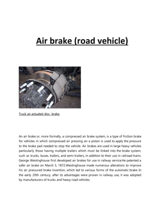
Truck air actuated disc brake.
An air brake or, more formally, a compressed air brake system, is a type of friction brake
for vehicles in which compressed air pressing on a piston is used to apply the pressure
to the brake pad needed to stop the vehicle. Air brakes are used in large heavy vehicles
particularly those having multiple trailers which must be linked into the brake system,
such as trucks, buses, trailers, and semi-trailers, in addition to their use in railroad trains.
George Westinghouse first developed air brakes for use in railway service.He patented a
safer air brake on March 5, 1872.Westinghouse made numerous alterations to improve
his air pressured brake invention, which led to various forms of the automatic brake. In
the early 20th century, after its advantages were proven in railway use, it was adopted
by manufacturers of trucks and heavy road vehicles.
2. Design and function
Air brake systems are typically used on heavy trucks and buses. The system consists of service
brakes, parking brakes, a control pedal, and an air storage tank. For the parking brake, there is a
disc or drum arrangement which is designed to be held in the 'applied' position by spring
pressure. Air pressure must be produced to release these "spring brake" parking Design and
function brakes. For the service brakes (the ones used while driving for slowing or stopping) to
be applied, the brake pedal is pushed, routing the air under pressure (approx 100–120 psi or
690–830 kPa or 6.89–8.27 bar) to the brake chamber, causing the brake to be engaged. Most
types of truck air brakes are drum brakes, though there is an increasing trend towards the use
of disc brakes. The air compressor draws filtered air from the atmosphere and forces it into
high-pressure reservoirs at around 120 psi (830 kPa; 8.3 bar). Most heavy vehicles have a gauge
within the driver's view, indicating the availability of air pressure for safe vehicle operation,
often including warning tones or lights. A mechanical "wig wag" that automatically drops down
into the driver's field of vision when the pressure drops below a certain point is also common.
Setting of the parking/emergency brake releases the pressurized air in the lines between the
compressed air storage tank and the brakes, thus allowing the spring actuated parking brake to
engage. A sudden loss of air pressure would result in full spring brake pressure immediately.
A compressed air brake system is divided into a supply system and a control system. The supply
system compresses,stores and supplies high-pressure air to the control system as well as to
additional air operated auxiliary truck systems (gearbox shift control, clutch pedal air assistance
servo, etc.).
Supply system
3. Highly simplified air brake diagram on a commercial road vehicle ( does not show all air
reservoirs and all applicable air valves ).
The air compressor is driven by the engine either by crankshaft pulley via a belt or directly from
the engine timing gears. It is lubricated and cooled by the engine lubrication and cooling
systems. Compressed air is first routed through a cooling coil and into an air dryer which
removes moisture and oil impurities and also may include a pressure regulator, safety valve and
smaller purge reservoir. As an alternative to the air dryer, the supply system can be equipped
with an anti-freeze device and oil separator. The compressed air is then stored in a supply
reservoir (also called a wet tank) from which it is then distributed via a four-way protection
valve into the primary reservoir (rear brake reservoir) and the secondary reservoir (front/trailer
brake reservoir), a parking brake reservoir, and an auxiliary air supply distribution point. The
system also includes various check, pressure limiting, drain and safety valves.Air brake systems
may include a wig wag device which deploys to warn the driver if the system air pressure drops
too low.
Control system
The control system is further divided into two service brake circuits, the parking brake circuit,
and the trailer brake circuit. The dual service brake circuits are further split into front and rear
wheel circuits which receive compressed air from their individual reservoirs for added safety in
case of an air leak. The service brakes are applied by means of a brake pedal air valve which
regulates both circuits. The parking brake is the air operated spring brake type where its
applied by spring force in the spring brake cylinder and released by compressed air via a hand
control valve. The trailer brake consists of a direct two line system: the supply line (marked red)
and the separate control or service line (marked blue). The supply line receives air from the
prime mover park brake air tank via a park brake relay valve and the control line is regulated via
the trailer brake relay valve. The operating signals for the relay are provided by the prime
mover brake pedal air valve, trailer service brake hand control (subject to local heavy vehicle
legislation) and the prime mover park brake hand control.
4. Trailer Control Valve Spring brake air cylinder Air brake foot valve
Trailer brake relay valve Truck air compressor Electronic air dryer
5. Air brakes relay valve Four way protection valve
Advantages
Air brakes are used as an alternative to hydraulic brakes which are used on lighter vehicles such
as automobiles. Hydraulic brakes use a liquid (hydraulic fluid) to transfer pressure from the
brake pedal to the brake shoe to stop the vehicle. Air brakes are used in heavy commercial
vehicles due to their reliability. They have several advantages for large multi-trailer vehicles:
The supply of air is unlimited, so the brake system can never run out of its operating fluid, as
hydraulic brakes can. Minor leaks do not result in brake failures.
Air line couplings are easier to attach and detach than hydraulic lines; the risk of air getting into
hydraulic fluid is eliminated, as is the need to bleed brakes when they are serviced. Air brake
circuits on trailers can be easily attached and removed.
Air not only serves as a fluid for transmission of force, but also stores potential energy as it is
compressed, so it can serve to control the force applied; hydraulic fluid is nearly
incompressible. Air brake systems include an air tank that stores sufficient energy to stop the
vehicle if the compressor fails.
Air brakes are effective even with considerable leakage, so an air brake system can be designed
with sufficient "fail-safe" capacity to stop the vehicle safely even when leaking.
6. Disadvantages
Although air brakes are readily considered the superior braking system for heavy vehicles,
generally those with a maximum gross vehicle weight rating (GVWR) of 26,000 to 33,000
pounds or more, which would over load hydraulic brakes, they also have the following
disadvantages, when compared to hydraulic braking systems:
Air brakes generally cost more.
Air brake systems compress air, which results in moisture that requires air dryers to remove,
which also increases the price for air brake systems and can contribute to higher maintenance
and repair costs, particularly in the first five years.
In the U.S. commercial drivers are required to obtain additional training and licensing, known as
an “endorsement,” in order to legally drive any vehicle using an air brake system. The Federal
Motor Carrier Safety Administration (FMCSA), which regulates the trucking industry in the U.S.,
requires that drivers who operate a vehicle equipped with air brakes take their driving test in
one.
Learning to operate air brakes smoothly has a learning curve, as they are difficult to operate
smoothly.
Also, since air brakes must be operated differently from hydraulic systems, driving a vehicle
with air brakes requires knowledge of proper maintenance. A driver is required to inspect the
air pressurization system prior to driving and make sure all tanks are in working order.
As noted by the Insurance Corporation of British Columbia (ICBC), “Operating commercial
vehicles or vehicles equipped with air brakes requires special knowledge and skill, and the cost
of a mistake can be very high. When large vehicles are involved in crashes, the damage—to
vehicles, cargo and human lives—can be catastrophic.
THE COMPONENTS OF AN AIR BRAKE SYSTEM
A basic air brake system capable of stopping a vehicle has five main components:
1. A COMPRESSOR, to pump air
2. A RESERVOIR OR TANK, to store the compressed air
3. A FOOT VALVE, to regulate the flow of compressed air
7. from the reservoir when it is needed for braking
4. BRAKE CHAMBERS & SLACK ADJUSTERS, the means of
transferring the force exerted by the compressed air to
mechanical linkages
5. BRAKE LININGS AND DRUM OR ROTORS, to create the friction required to stop the wheels It
is necessary to understand how each of these components works before studying their
functions in the air brake system .
1. Air Compressor
An air compressor maintains the proper level of air pressure so that the air brakes and
any other air-powered accessories operate safely and consistently.
Depending on the make and model of your heavy truck, its compressor is either gear or
belt-driven and gets cooled by either air or an engine cooling system. The
compressor(s) startup every time the engine is triggered, and the device loads and
unloads air which is pumped in and out of the reservoirs and the other two-cylinder
compressors.
2. Reservoirs
In the case of heavy truck and bus air brake systems, it’s the reservoirs that hold onto a
sufficient amount of compressed air, until the supply is required for braking. Note:
drivers cannot control the amount of air that they use when the air brakes are triggered;
the amount solely depends on how much has been circulated by the compressor.In
terms of design, reservoirs are pressure-rated tanks that feature special drain valves
called draincocks. When the draincocks are in the ‘open’ position, they drain themselves
of any moisture or pollutants that might compromise the integrity of the air.
3. Foot Valve
The foot valve, otherwise known as the treadle or the brake pedal, is the tool that
determines the volume of air pressure used. In this case, the volume is determined by
how hard the operator presses their footon the foot valve.When the compressed air is
released through the brake system, it takes time for it to be produced again through the
compressor function (described above). That said, if too much pressure is released in a
short period of time, the entire system could fail.
8. 4. Brake Chambers
Brake chambers, otherwise known as brake pots, are the devices that turn the
compressed air into mechanical force. It is through this mechanism that the brakes are
triggered and the heavy truck or bus is able to safely halt.
Each one of the brake chambers comes equipped with a specific pushrod stroke
adjustment limit. The chamber itself is held together by a clamp assembly that is
specially made to regulate the compressed air that is released into the chambers.
5. Brake Shoes and Drums
By making use of friction, the brake shoes – or pads, depending on the make and model
of the truck – are forced outwards, thus initiating the air brake system.A special brake
lining material is attached to the brake shoes to help promote consistency. If the type of
lining is a good fit, it should also regulate heat that is created from the friction.
Using Air Brakes
Normal Stops
To apply the air brakes during normal stops, push the brake pedal down. Control the
pressure so the vehicle comes to a smooth, safe stop. If you have a manual
transmission, do not push the clutch in until the engine RPM is down close to idle. When
stopped, select a starting gear.
Emergency Stops
If somebody suddenly pulls out in front of you, your natural response is to hit the brakes.
This is a good response if there is enough distance to stop and you use the brakes
correctly You should brake in a way that will keep your vehicle in a straight line and
allow you to turn if it becomes necessary. You can use the “controlled braking” method
or the “stab braking” method.
Controlled braking:
With this method, you apply the brakes as hard as you can without locking the wheels.
Keep steering wheel movements very small while doing this. If you need to make larger
9. steering adjustments or if the wheels lock, release the brakes. Reapply the brakes as
soon as you can.
Stab braking:
Use only on vehicles without anti-lock systems.
Apply the brake all the way.
Release the brakes when the wheels lock up.
As soon as the wheels start rolling, put on the brakes fully again. It can take up to 1
second for the wheels to start rolling after you release the brakes. If you reapply the
brakes before the wheels start rolling, the vehicle will not straighten out.
Anti-lock Brakes
New trucks and truck-trailer vehicles are equipped with anti-lock brakes. The anti-lock
braking system is different than the normal air-brake system but works on the same
principle.Vehicles that have anti-lock brakes have a yellow light near the driverʼs rear
side of the vehicle with the letters ABS stenciled above the light. Once the driver turns
on the ignition, a yellow malfunction lamp on the instrument panel will light up, briefly
indicating that the vehicle has anti-lock brakes. This lamp will remain constant if there is
a malfunction in the anti-lock brake system.For normal or emergency stopping using
anti-lock brakes, the driverʼs foot remains on the brake pedal in which the anti-lock
module then acts as a foot pumping the air brake system. On the air-brake system the
driver must pump or use stab braking in an emergency. If the anti-lock brake system
fails or malfunctions, the driver must resort to stopping the vehicle by using the normal
air-brake method. If an emergency arises, the driver should use the controlled or stab
braking method. The anti-lock brake system should be serviced as soon as possible.
Stopping Distance
Stopping distance was discussed in Section 2: Speed and Stopping Distance. With air
brakes, there is an added delay – the time required for the brakes to work after the
brake pedal is pushed. With hydraulic brakes (used on cars and light /medium trucks),
the brakes work instantly. However, with air brakes, it takes a little time (one-half
second or more) for the air to flow through the lines to the brakes. Thus, the total
stopping distance for vehicles with air brake systems is made up of four different
factors:
10. Perception Distance
+ Reaction Distance
+ Brake Lag Distance
+ Effective Braking Distance
------------------------------
= Total Stopping Distance
The air brake lag distance at 55 mph on dry pavement adds about 32 feet. Therefore,
for an average driver traveling 55 mph under good traction and brake conditions, the
total stopping distance is more than 300 feet.