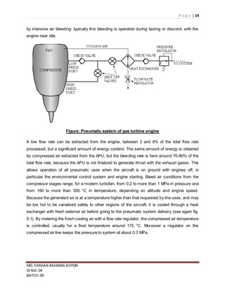
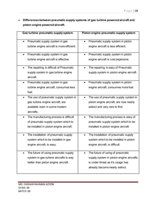
P a g e | 1
MD. FARHAN RAHMAN AOYON
ID NO: 04
BATCH: 09
Task-1a (P1)
 Three purposes of pneumatic systems are given below:
1. Pneumatic systems are used in air-conditioning system and pressurization system of
aircraft.
2. For aircraft anti-icing and deicing systems pneumatic systems are used.
3. It can be used for engine starting system and gas turbine compressor.
 The functions of piston engine, air compressor and receiver are describes below:
(a) Function of piston engine:
The Otto cycle is the ideal air standard cycle for the spark ignition piston engine. In this cycle it
is assumed that the working fluid, air, behaves as a perfect gas and that there is no change in
the composition of the air during the complete cycle. Heat transfer occurs at constant volume
and there is reversible adiabatic compression and expansion. This piston cycle differs from the
practical engine cycle in that the same quantity of working fluid is used repeatedly and so an
induction and exhaust stroke are unnecessary. The thermodynamic processes making up a
complete piston engine Otto cycle are detailed below:
Figure: Working cycle of piston engine
P a g e | 2
MD. FARHAN RAHMAN AOYON
ID NO: 04
BATCH: 09
1–2 Adiabatic compression takes place. No heat transfer takes place, temperature and pressure
increase and the volume decrease to the clearance volume.
2–3 Reversible constant volume heating, temperature and pressure increase.
3–4 Adiabatic expansion (through swept volume) takes place. Air expands and does work on
the piston. Pressure and temperature fall. No heat transfer takes place, during the process.
4–1 Reversible constant volume heat rejection (cooling). Pressure and temperature fall to
original values.
During the compression and expansion of the working fluid, the ideal Otto cycle assumes that
no heat is transferred to or from the working fluid during the process.
(b) Function of air compressor:
An air compressor is a machine that uses an electric motor or gas engine to power a device that
sucks in successive volumes of air from the atmosphere, compresses (squeezes) each volume
of air in a confined place to increase its pressure by making the volume smaller, and then
transfers the high-pressure air to a receiver tank.
(c) Function of air receiver:
The receiver usually stores enough compressed air for several applications. From the air
compressor this high pressure air is then stored in the air receiver until it is needed. The Air
receiver is basically a metal bottle. The high-pressure air is drawn off from the receiver tank to
power equipment. Such as:
A high pressure air line connects the bottle to an air valve which controls operation of the
emergency brakes. If the normal brake system fails, place the control handle for the air valve in
the "on" position. The valve then directs high-pressure air into lines leading to the brake
assemblies. But before air enters the brake assemblies, it must first flow through a shuttle valve.
P a g e | 3
MD. FARHAN RAHMAN AOYON
ID NO: 04
BATCH: 09
Task-1b (P2)
 How bleed air is supplied to the system pre-cooler from turbine engine is describes
below:
On most jetliners, air is supplied to the ECS by being "bleed" from a compressor stage of
each gas turbine engine, upstream of the combustor. The temperature and pressure of this
"bleed air" varies widely depending upon which compressor stage and the RPM of the engine.
Figure: Bleed air supplied to system pre-cooler from engine
A "Manifold Pressure Regulating Shut-Off Valve" (MPRSOV) restricts the flow as necessary to
maintain the desired pressure for downstream systems. This flow restriction results in efficiency
losses. To reduce the amount of restriction required, and thereby increase efficiency, air is
commonly drawn from two bleed ports.
When the engine is at low thrust, the air is drawn from the "High Pressure Bleed Port." As thrust
is increased, the pressure from this port rises until "crossover," where the "High Pressure Shut-
Off Valve" (HPSOV) closes and air is thereafter drawn from the "Low Pressure Bleed Port."
To achieve the desired temperature, the bleed-air is passed through a heat exchanger called a
"pre-cooler." Air from the jet engine fan is blown across the pre-cooler, which is located in the
engine strut. A "Fan Air Modulating Valve" (FAMV) varies the cooling airflow, and thereby
controls the final air temperature of the bleed air.
P a g e | 4
MD. FARHAN RAHMAN AOYON
ID NO: 04
BATCH: 09
Task-1c (P3)
 The purposes of the given aircraft pneumatic supply systems are state below:
Cabin air conditioning system:
The function of an air conditioning system is to maintain a comfortable air temperature within the
aircraft fuselage. The system will increase or decrease the temperature of the air as needed to
obtain the desired value. Most systems are capable of producing an air temperature of 70
0
to
80
0
F. with normally anticipated outside air temperatures. This temperature-conditioned air is
then distributed so that there is a minimum of stratification (hot and cold layers). The system, in
addition, must provide for the control of humidity, it must prevent the fogging of windows, and it
must maintain the temperature of wall panels and floors at a comfortable level.
Cabin pressurization system:
When an aircraft is flown at a high altitude, it burns less fuel for a given airspeed than it does for
the same speed at a lower altitude. In other words, the airplane is more efficient at a high
altitude. In addition, bad weather and turbulence can be avoided by flying in the relatively
smooth air above the storms. Aircraft which do not have pressurization and air conditioning
systems are usually limited to the lower altitudes.
A cabin pressurization system must accomplish several functions if it is to assure adequate
passenger comfort and safety. It must be capable of maintaining a cabin pressure altitude of
approximately 8,000 ft. at the maximum designed cruising altitude of the aircraft. The system
must also be designed to prevent rapid changes of cabin altitude which may be uncomfortable
or injurious to passengers and crew. In addition, the pressurization system should permit a
reasonably fast exchange of air from inside to outside the cabin. This is necessary to eliminate
odors and to remove stale air.
 The functions of the given things of aircraft pneumatic supply system are given
below:
Ram air:
It is more of ventilation system rather than cooling or conditioning system. Ram air taken from
atmosphere is made to pass over engine exhaust air outlet pipes which assist in raising the
P a g e | 5
MD. FARHAN RAHMAN AOYON
ID NO: 04
BATCH: 09
temperature. Heated air can now be mixed with cold ram air to obtain desired level on
temperature and same can be introduced in cockpit.
Bleed air:
In bleed air system compressed air is taken from two stages of compressor to meet the
adequate flow requirements with varying compressor RPM or thrust settings. In order to prevent
air flow from high pressure to low pressure duct, non return valve is fitted to low pressure duct.
A high pressure shutoff valve is fitted to the high pressure duct in order to modulate/stop the
flow of air from high pressure stage incase aircraft is flying at sufficiently higher speeds. Once
the flow from both the stages is merge, a valve to govern the amount of flow entering main
system is added to main line namely Bleed Air Valve.
In order to reduce and distribute the workload, the bleed air requirement by the system is
distributed to both the engines (for multi engine) of aircraft. Should there be any lag in air supply
by one engine due failure or other problem, the isolation valve can be opened so that live
engine can assist the system functioning
Air cycle unit:
An air cycle cooling system consists of an expansion turbine (cooling turbine), an air-to-air heat
exchanger, and various valves which control airflow through the system. The expansion turbine
incorporates an impeller and a turbine on a common shaft. High-pressure air from the cabin
compressor is routed through the turbine section. As the air passes through the turbine, it
rotates the turbine and the impeller. When the compressed air performs the work of turning the
turbine, it undergoes a pressure and temperature drop. It is this temperature drop which
produces the cold air used for air conditioning.
Humidifier:
When aircraft is flying at very high altitudes like 30,000ft or so, the moisture content in ambient
air is almost negligible. In order to aid comfortable respiration, some moisture can be added to
air. Drinking water stored in the pressurized tank is splashed in downstream of air flow from
water separator or air cycle unit and any excess moisture is absorbed by fabric covered spill
vanes fitted in path of air flow. The amount of moisture added by humidifier can be controlled by
pilot with the data given by humidity sensor fitted at outlet of humidifier.
P a g e | 6
MD. FARHAN RAHMAN AOYON
ID NO: 04
BATCH: 09
 How conditioned air is supplied from intercooler to the aircraft cabin is describes
below:
Air conditioning prepares engine bleed air to pressurize the aircraft cabin. The temperature and
quantity of the air must be controlled to maintain a comfortable cabin environment at all altitudes
and on the ground. The air cycle system is often called the air conditioning package or pack. It
is usually located in the lower half of the fuselage or in the tail section of turbine-powered
aircraft.
Figure: Air conditioning system
Even with the frigid temperatures experienced at high altitudes, bleed air is too hot to be used in
the cabin without being cooled. It is let into the air cycle system and routed through a heat
exchanger where ram air cools the bleed air. This cooled bleed air is directed into an air cycle
machine. There, it is compressed before flowing through a secondary heat exchange that cools
the air again with ram air. The bleed air then flows back into the air cycle machine where it
drives an expansion turbine and cools even further. Water is then removed and the air is mixed
with bypassed bleed air for final temperature adjustment. It is sent to the cabin through the air
distribution system. By examining the operation of each component in the air cycle process, a
better understanding can be developed of how bleed air is conditioned for cabin use.
P a g e | 7
MD. FARHAN RAHMAN AOYON
ID NO: 04
BATCH: 09
Task - 1d (P10)
Job title:
Replace the check valve of engine bleed air system.
Safety equipments:
 Safety goggles.
 Gloves.
 Safety Shoes
 Apron
 Face Mask
 Helmet and etc.
Tools Needed:
 Cutter
 22 mm ring spanner.
 19 mm open end spanner.
 Nose Pliers.
 Locking wire
 Cleaning rag.
Disassemble procedure:
1. First I cut off the wire locks using cutter.
2. Removed the check valve nuts on each side opening nuts on opposite sides.
3. Then I removed the bigger nuts under check valve nuts by using 22mm ring spanner.
4. Removed circlip using nose pliers.
P a g e | 8
MD. FARHAN RAHMAN AOYON
ID NO: 04
BATCH: 09
5. Then I serially took out the body, spool, spring, valve, fittings and nut.
Replace procedure:
1. Firstly, serially put on the body, spool, spring, valve, fittings and nut.
2. Then I put on the circlip using nose pliers.
3. Then used 22 mm ring spanner to fit the bigger nut beneath the check valve nut.
4. Then by using 19mm spanner we fitted the check valve nuts on each side.
5. Then again fitted the locking wire.
6. At last we settled the check valve into the system.
Safety precaution:
 Proper tools should be used
 After the re-installing it should wire lock.
 Pliers gripe should not be moveable.
 Fuel system should be depressurized
 To stop fuel supply, reservoir should be empty
 Put tag on cockpit to avoid other people using this system
 When I took the tools needed, I have registered the tools before taking them out of the
workshop.
P a g e | 9
MD. FARHAN RAHMAN AOYON
ID NO: 04
BATCH: 09
Task – 1e (P11)
I.
Job title:
Replace bleed air wing isolation valve.
Safety equipments:
Safety goggles.
 Gloves.
 Safety Shoes
 Apron
 Face Mask
 Helmet
 All kinds of safety equipments.
Required Tools:
 Open ended ring spanner (size 8 mm).
 Cutter.
 Pliers.
Disassemble procedure:
 At first I cut the wire locking by using cutter.
 Then I removed the nuts and bolt of wing isolation valve by using open ended spanner
(size 8mm)
 After that I remove the cover plate of the wing isolation valve.
P a g e | 10
MD. FARHAN RAHMAN AOYON
ID NO: 04
BATCH: 09
 Then clean it with the cleaning rag.
Replace procedure:
 I fitted cover plate back of the wing isolation valve.
 Then I tightened nuts and bolts with hand.
 After that I tightened by using spanner.
 At last wire lock the wing isolation valve.
Safety precaution:
 Proper tool should be used.
 Tools should be lubricant and oil free.
 Tag should be place in starter switch in cockpit
 Completely drain the fuel tanks before work
 When I took the tools needed, I have registered the tools before taking them out of the
workshop.
P a g e | 11
MD. FARHAN RAHMAN AOYON
ID NO: 04
BATCH: 09
II.
Job title:
Replace cabin safety valve.
Safety equipments:
 Safety goggles.
 Gloves.
 Safety Shoes
 Apron
 Face Mask
 Helmet
 All kinds of safety equipments.
Tools Needed:
 27 mm ring spanner
 Wire locking
 Cutter
 Phillip Screw driver
Disassemble procedure:
 At first cut off the wire locking.
 Unscrew the screw with Phillip screw driver
 Using 27mm ring spanner, remove nuts
 Take out the spring carefully.
 After that take out the safety valve.
P a g e | 12
MD. FARHAN RAHMAN AOYON
ID NO: 04
BATCH: 09
Replace procedure:
 At first put the safety valve.
 Then put the spring.
 And then tighten the union by using spanner.
 Then fit the cabin safety valve into the system.
Safety precaution:
 When I took the tools needed, I have registered the tools before taking them out of the
workshop.
 System should be depressurized during operation.
 Tag should be place on cockpit to avoid people using of system
 Proper tools should be used for avoiding damage to parts.
P a g e | 13
MD. FARHAN RAHMAN AOYON
ID NO: 04
BATCH: 09
Task – 1f (M1)
 Pneumatic supply system of piston engine and gas turbine engine are explained
below:
Pneumatic supply system of piston engine:
Many aircraft equipped with reciprocating or piston engines obtain a supply of low-pressure air
from vane-type pumps. These pumps are driven by electric motors or by the aircraft engine.
Pump compresses air tat raising air pressure to above ambient pressure for use in pneumatic
systems. Then one-way valve allows pressurized air to enter the pneumatic system, but
prevents backflow of air toward the Compressor when Compressor is stopped (prevent loss of
pressure. Accumulator then Stores compressed air, Prevents surges in pressure Prevents
constant Compressor operation (“duty cycles” of Compressor). Directional valve Controls
pressurized air flow from Accumulator (source to user equipment via selected port some valves
are one way shut tight Some valves are two way, allowing free exhaust from the port not
selected valves can be actuated manually or electrically. Then actuator converts energy stored
in compressed air into mechanical motion. Thus, the pump delivers to the pneumatic system a
continuous supply of compressed air from 1 to 10 psi. Low-pressure systems are used for wing
deicing boot systems.
Pneumatic supply system of gas turbine engine:
The turbine engine is a generator of high-speed gas aimed to provide thrust for the aircraft.
Before entering the combustion chamber and being mixed with atomized fuel, the external air is
processed by a multi-stage axial compressor, driven by the turbine. From one or more stages of
the compressor, a limited volume of air can be bled without significant degradation of the engine
performances.
Air is commonly bled at two different stages of the compressor: a low pressure port at an
intermediate stage (around 7TH stage) and a high pressure port at a final stage (around 15TH
stage). A check valve is necessary to prevent air flowing from high to low pressure bleeding
ports. The low pressure bleeding port is normally open, but can be excluded with the shut-off
valve if the engine is in critical conditions; the high pressure port is open when the pressure
coming from the intermediate stage is not adequate, or a considerable amount of air is
necessary, and anyway the engine must be in operating conditions that cannot be deteriorated
P a g e | 14
MD. FARHAN RAHMAN AOYON
ID NO: 04
BATCH: 09
by intensive air bleeding: typically this bleeding is operated during taxiing or descent, with the
engine near idle.
Figure: Pneumatic system of gas turbine engine
A low flow rate can be extracted from the engine, between 2 and 8% of the total flow rate
processed, but a significant amount of energy content. The same amount of energy is obtained
by compressed air extracted from the APU, but the bleeding rate is here around 70-80% of the
total flow rate, because the APU is not finalized to generate thrust with the exhaust gases. This
allows operation of all pneumatic uses when the aircraft is on ground with engines off, in
particular the environmental control system and engine starting. Bleed air conditions from the
compressor stages range, for a modern turbofan, from 0.2 to more than 1 MPa in pressure and
from 180 to more than 350 °C in temperature, depending on altitude and engine speed.
Because the generated air is at a temperature higher than that requested by the uses, and may
be too hot to be canalised safely to other regions of the aircraft, it is cooled through a heat
exchanger with fresh external air before going to the pneumatic system delivery (see again fig.
5.1). By metering the fresh cooling air with a flow rate regulator, the compressed air temperature
is controlled, usually for a final temperature around 175 °C. Moreover a regulator on the
compressed air line keeps the pressure to system at about 0.3 MPa.
P a g e | 15
MD. FARHAN RAHMAN AOYON
ID NO: 04
BATCH: 09
 Differences between pneumatic supply systems of gas turbine powered aircraft and
piston engine powered aircraft:
Gas turbine pneumatic supply system Piston engine pneumatic supply system
 Pneumatic supply system in gas
turbine engine aircraft is more efficient.
 Pneumatic supply system in piston
engine aircraft is less efficient.
 Pneumatic supply system in gas
turbine engine aircraft is effective.
 Pneumatic supply system in piston
engine aircraft is cost expensive.
 The repairing is difficult of Pneumatic
supply system in gas turbine engine
aircraft.
 The repairing is easy of Pneumatic
supply system in piston engine aircraft.
 Pneumatic supply system in gas
turbine engine aircraft, consumes less
fuel.
 Pneumatic supply system in piston
engine aircraft, consumes more fuel.
 The use of pneumatic supply system in
gas turbine engine aircraft, are
available even in some modern
aircrafts.
 The use of pneumatic supply system in
piston engine aircraft, are now nearly
extinct and very rare to find.
 The manufacturing process is difficult
of pneumatic supply system which to
be installed in piston engine aircraft.
 The manufacturing process is easy of
pneumatic supply system which to be
installed in piston engine aircraft.
 The installation of pneumatic supply
system which to be installed in gas
engine aircraft, is easy.
 The installation of pneumatic supply
system which to be installed in piston
engine aircraft, is difficult.
 The future of using pneumatic supply
system in gas turbine aircrafts is way
better than piston engine aircraft.
 The future of using of pneumatic
supply system in piston engine aircrafts
is under threat as it’s usage has
already become nearly extinct.
P a g e | 16
MD. FARHAN RAHMAN AOYON
ID NO: 04
BATCH: 09
Task – 1g (M2)
 The function of the given components of air conditioning system is given below:
Sensors:
Cabin temperature pickup units and duct temperature sensors used in the temperature control
system are thermistors. Their resistance changes as temperature changes. The temperature
selector is a rheostat that varies its resistance as the knob is turned. In the temperature
controller, resistances are compared in a bridge circuit. The bridge output feeds a temperature
regulating function. An electric signal output is prepared and sent to the valve that mixes hot
and cold air. On large aircraft with separate temperature zones, trim air modulating valves for
each zone are used. The valves modulate to provide the correct mix required to match the
selected temperature. Cabin, flight deck, and duct temperature sensors are strategically located
to provide useful information to control cabin temperature.
Duct stats:
Ducts having circular or rectangular cross sections are most frequently used in air distribution
systems. Circular ducts are used wherever possible. Rectangular ducts are generally used
where circular ducts cannot be used because of installation or space limitations. Rectangular
ducts may be used in the cabin where a more pleasing appearance is desired. Distribution ducts
for various cabin zones, individual air outlets for passengers, and window demisters can have
various shapes. Cabin air supply ducts are usually made from aluminium alloys, stainless steel,
or plastic. Main ducts for air temperatures over 200
0
C. are made from stainless steel.
Motor operated valve:
The use of electric motors to operate air conditioning system valves is common on large aircraft
due to the remote location from the cockpit of air system components. The types of valves used
are basically the same as the manually operated valves, but electric motors are used to actuate
the units. The two most common electric motor operated air valves are the gate valve and the
plug-type valve. The motor-operated gate valve uses a geared, reversible electric motor to turn
the actuating arm of the valve that moves the fuel gate into or out of the path of the air. As with
the manually operated gate valve, the gate or blade is sealed. A manual override lever allows
the technician to observe the position of the valve or manually position it. Regardless of the type
of valve used, large aircraft air conditioning systems.
P a g e | 17
MD. FARHAN RAHMAN AOYON
ID NO: 04
BATCH: 09
 How cabin temperature is controlled by using sensors, duct stats and motor operated
valves are explained below:
Most cabin temperature control systems operate in a similar manner. Temperature is monitored
in the cabin, cockpit, conditioned air ducts, and distribution air ducts. These values are input into
a temperature controller, or temperature control regulator, normally located in the electronics
bay. A temperature selector in the cockpit can be adjusted to input the desired temperature. The
temperature controller compares the actual temperature signals received from the various
sensors with the desired temperature input. Circuit logic for the selected mode processes these
input signals. An output signal is sent to a valve in the air cycle air conditioning system. This
valve has different names depending on the aircraft manufacturer and design of the
environmental control systems. It mixes warm bleed air that bypassed the air cycle cooling
process with the cold air produced by it. By modulating the valve in response to the signal from
the temperature controller, air of the selected temperature is sent to the cabin through the air
distribution system.
Figure: Cabin Temperature Control System
P a g e | 18
MD. FARHAN RAHMAN AOYON
ID NO: 04
BATCH: 09
Cabin temperature pickup units and duct temperature sensors used in the temperature control
system are thermistors. Their resistance changes as temperature changes. The temperature
selector is a rheostat that varies its resistance as the knob is turned. In the temperature
controller, resistances are compared in a bridge circuit. The bridge output feeds a temperature
regulating function. An electric signal output is prepared and sent to the valve that mixes hot
and cold air. On large aircraft with separate temperature zones, trim air modulating valves for
each zone are used. The valves modulate to provide the correct mix required to match the
selected temperature. Cabin, flight deck, and duct temperature sensors are strategically located
to provide useful information to control cabin temperature.
Task – 1h (D11)
I.
 The normal operation of cabin pressurization system with given steps are explained
below:
Before takeoff:
 Turn the rate knob to the desire rate.
 Set the cabin altitude knob to the desire cabin altitude.
 Never set cabin altitude than failed pressure altitude.
 Set the air conditioning master switch to “air conditioning auto press”.
After takeoff climb:
 Set the rate knob to the desire rate.
 Adjust the rate setting as required during climb so that the cabin reaches the selected
altitude at the same time the aircraft reaches cruise altitude.
 Thus, the rate pressure change is held to a minimum.
 The rate of cabin pressure change is held constant only up to pressure controller
differential limit.
P a g e | 19
MD. FARHAN RAHMAN AOYON
ID NO: 04
BATCH: 09
 Monitor cabin altitude against aircraft altitude to make sure that cabin altitude stays
within the isobaric range.
Cruise:
 During pressurized flight, monitor the cabin differential pressure and cabin altitude.
 Do not allow the cabin differential pressure to exceed the maximum allowable for the
aircraft.
Descent:
 Set the cabin altitude knob to the desire cabin altitude.
 Set the rate knob to the desire rate.
Before landing:
 Check the cabin differential pressure before landing.
 If more than 1.5 inches of mercury indicated, the cabin altitude selector and the rate
knob should be adjusted to the higher setting to increase the rate of depressurization.
 Cabin differential pressure will be zero for landing.
 If less than 0.5 inches of mercury indicated, no discomfort will be experienced. If the air
conditioning master switch is turned to a non-pressure position.
P a g e | 20
MD. FARHAN RAHMAN AOYON
ID NO: 04
BATCH: 09
II.
 The emergencyoperation of cabin pressurization system on ground is explained
below:
An emergency depressurization door, located in the center escape hatch, is released by pulling
the emergency depressurization handle on the overhead control panel directly above the pilot.
The handle is connected by a cable to the release mechanism of the door which is restrained
from consequential loss by two shock cords. After depressurization is accomplished, the door
can be replaced and the release mechanism reset manually.
Figure: Emergency depressurization handle
P a g e | 21
MD. FARHAN RAHMAN AOYON
ID NO: 04
BATCH: 09
References:-
Unit – 82, Airframe systems
C-130 Maintenance manual (Section 4 - Auxiliary equipments)
Class note
Class lecture
Aviation maintenance technician handbook (Airframe, Volume-2)
Aviation maintenance technician handbook (Power-plant, Volume-2)
http://uk.answers.yahoo.com/question/index?qid=20120425100301AA3b98p
Aircraft engineering principle by Mike Tooley
http://en.wikipedia.org/wiki/Environmental_control_system_%28aircraft%29
http://www.google.com.bd/url?sa=t&rct=j&q=&esrc=s&source=web&cd=7&cad=rja&uact
=8&ved=0CEEQFjAG&url=http%3A%2F%2Fwww.aero.polimi.it%2F~l050263%2Fbache
ca%2FDispense_EN%2F05w-PneuSyst.pdf&ei=cRQrU7G-OqSL0AX-
_YHAAQ&usg=AFQjCNFenXJCdevbdGWEzx-Okibgkah8vQ&bvm=bv.62922401,d.d2k
http://www.google.com.bd/url?sa=t&rct=j&q=&esrc=s&source=web&cd=1&cad=rja&uact
=8&ved=0CCgQFjAA&url=http%3A%2F%2Fwww.instruction.greenriver.edu%2Faviation
%2Fdownloads%2Favia112_files%2Fpneumatics.pdf&ei=6horU-
fZM4ua0QXY14GgCw&usg=AFQjCNFVyw1euNiqZr7sVbtnu6IdqnoEPA&bvm=bv.62922
401,d.d2k

Airframe 1 (done)

  • 1.
    P a ge | 1 MD. FARHAN RAHMAN AOYON ID NO: 04 BATCH: 09 Task-1a (P1)  Three purposes of pneumatic systems are given below: 1. Pneumatic systems are used in air-conditioning system and pressurization system of aircraft. 2. For aircraft anti-icing and deicing systems pneumatic systems are used. 3. It can be used for engine starting system and gas turbine compressor.  The functions of piston engine, air compressor and receiver are describes below: (a) Function of piston engine: The Otto cycle is the ideal air standard cycle for the spark ignition piston engine. In this cycle it is assumed that the working fluid, air, behaves as a perfect gas and that there is no change in the composition of the air during the complete cycle. Heat transfer occurs at constant volume and there is reversible adiabatic compression and expansion. This piston cycle differs from the practical engine cycle in that the same quantity of working fluid is used repeatedly and so an induction and exhaust stroke are unnecessary. The thermodynamic processes making up a complete piston engine Otto cycle are detailed below: Figure: Working cycle of piston engine
  • 2.
    P a ge | 2 MD. FARHAN RAHMAN AOYON ID NO: 04 BATCH: 09 1–2 Adiabatic compression takes place. No heat transfer takes place, temperature and pressure increase and the volume decrease to the clearance volume. 2–3 Reversible constant volume heating, temperature and pressure increase. 3–4 Adiabatic expansion (through swept volume) takes place. Air expands and does work on the piston. Pressure and temperature fall. No heat transfer takes place, during the process. 4–1 Reversible constant volume heat rejection (cooling). Pressure and temperature fall to original values. During the compression and expansion of the working fluid, the ideal Otto cycle assumes that no heat is transferred to or from the working fluid during the process. (b) Function of air compressor: An air compressor is a machine that uses an electric motor or gas engine to power a device that sucks in successive volumes of air from the atmosphere, compresses (squeezes) each volume of air in a confined place to increase its pressure by making the volume smaller, and then transfers the high-pressure air to a receiver tank. (c) Function of air receiver: The receiver usually stores enough compressed air for several applications. From the air compressor this high pressure air is then stored in the air receiver until it is needed. The Air receiver is basically a metal bottle. The high-pressure air is drawn off from the receiver tank to power equipment. Such as: A high pressure air line connects the bottle to an air valve which controls operation of the emergency brakes. If the normal brake system fails, place the control handle for the air valve in the "on" position. The valve then directs high-pressure air into lines leading to the brake assemblies. But before air enters the brake assemblies, it must first flow through a shuttle valve.
  • 3.
    P a ge | 3 MD. FARHAN RAHMAN AOYON ID NO: 04 BATCH: 09 Task-1b (P2)  How bleed air is supplied to the system pre-cooler from turbine engine is describes below: On most jetliners, air is supplied to the ECS by being "bleed" from a compressor stage of each gas turbine engine, upstream of the combustor. The temperature and pressure of this "bleed air" varies widely depending upon which compressor stage and the RPM of the engine. Figure: Bleed air supplied to system pre-cooler from engine A "Manifold Pressure Regulating Shut-Off Valve" (MPRSOV) restricts the flow as necessary to maintain the desired pressure for downstream systems. This flow restriction results in efficiency losses. To reduce the amount of restriction required, and thereby increase efficiency, air is commonly drawn from two bleed ports. When the engine is at low thrust, the air is drawn from the "High Pressure Bleed Port." As thrust is increased, the pressure from this port rises until "crossover," where the "High Pressure Shut- Off Valve" (HPSOV) closes and air is thereafter drawn from the "Low Pressure Bleed Port." To achieve the desired temperature, the bleed-air is passed through a heat exchanger called a "pre-cooler." Air from the jet engine fan is blown across the pre-cooler, which is located in the engine strut. A "Fan Air Modulating Valve" (FAMV) varies the cooling airflow, and thereby controls the final air temperature of the bleed air.
  • 4.
    P a ge | 4 MD. FARHAN RAHMAN AOYON ID NO: 04 BATCH: 09 Task-1c (P3)  The purposes of the given aircraft pneumatic supply systems are state below: Cabin air conditioning system: The function of an air conditioning system is to maintain a comfortable air temperature within the aircraft fuselage. The system will increase or decrease the temperature of the air as needed to obtain the desired value. Most systems are capable of producing an air temperature of 70 0 to 80 0 F. with normally anticipated outside air temperatures. This temperature-conditioned air is then distributed so that there is a minimum of stratification (hot and cold layers). The system, in addition, must provide for the control of humidity, it must prevent the fogging of windows, and it must maintain the temperature of wall panels and floors at a comfortable level. Cabin pressurization system: When an aircraft is flown at a high altitude, it burns less fuel for a given airspeed than it does for the same speed at a lower altitude. In other words, the airplane is more efficient at a high altitude. In addition, bad weather and turbulence can be avoided by flying in the relatively smooth air above the storms. Aircraft which do not have pressurization and air conditioning systems are usually limited to the lower altitudes. A cabin pressurization system must accomplish several functions if it is to assure adequate passenger comfort and safety. It must be capable of maintaining a cabin pressure altitude of approximately 8,000 ft. at the maximum designed cruising altitude of the aircraft. The system must also be designed to prevent rapid changes of cabin altitude which may be uncomfortable or injurious to passengers and crew. In addition, the pressurization system should permit a reasonably fast exchange of air from inside to outside the cabin. This is necessary to eliminate odors and to remove stale air.  The functions of the given things of aircraft pneumatic supply system are given below: Ram air: It is more of ventilation system rather than cooling or conditioning system. Ram air taken from atmosphere is made to pass over engine exhaust air outlet pipes which assist in raising the
  • 5.
    P a ge | 5 MD. FARHAN RAHMAN AOYON ID NO: 04 BATCH: 09 temperature. Heated air can now be mixed with cold ram air to obtain desired level on temperature and same can be introduced in cockpit. Bleed air: In bleed air system compressed air is taken from two stages of compressor to meet the adequate flow requirements with varying compressor RPM or thrust settings. In order to prevent air flow from high pressure to low pressure duct, non return valve is fitted to low pressure duct. A high pressure shutoff valve is fitted to the high pressure duct in order to modulate/stop the flow of air from high pressure stage incase aircraft is flying at sufficiently higher speeds. Once the flow from both the stages is merge, a valve to govern the amount of flow entering main system is added to main line namely Bleed Air Valve. In order to reduce and distribute the workload, the bleed air requirement by the system is distributed to both the engines (for multi engine) of aircraft. Should there be any lag in air supply by one engine due failure or other problem, the isolation valve can be opened so that live engine can assist the system functioning Air cycle unit: An air cycle cooling system consists of an expansion turbine (cooling turbine), an air-to-air heat exchanger, and various valves which control airflow through the system. The expansion turbine incorporates an impeller and a turbine on a common shaft. High-pressure air from the cabin compressor is routed through the turbine section. As the air passes through the turbine, it rotates the turbine and the impeller. When the compressed air performs the work of turning the turbine, it undergoes a pressure and temperature drop. It is this temperature drop which produces the cold air used for air conditioning. Humidifier: When aircraft is flying at very high altitudes like 30,000ft or so, the moisture content in ambient air is almost negligible. In order to aid comfortable respiration, some moisture can be added to air. Drinking water stored in the pressurized tank is splashed in downstream of air flow from water separator or air cycle unit and any excess moisture is absorbed by fabric covered spill vanes fitted in path of air flow. The amount of moisture added by humidifier can be controlled by pilot with the data given by humidity sensor fitted at outlet of humidifier.
  • 6.
    P a ge | 6 MD. FARHAN RAHMAN AOYON ID NO: 04 BATCH: 09  How conditioned air is supplied from intercooler to the aircraft cabin is describes below: Air conditioning prepares engine bleed air to pressurize the aircraft cabin. The temperature and quantity of the air must be controlled to maintain a comfortable cabin environment at all altitudes and on the ground. The air cycle system is often called the air conditioning package or pack. It is usually located in the lower half of the fuselage or in the tail section of turbine-powered aircraft. Figure: Air conditioning system Even with the frigid temperatures experienced at high altitudes, bleed air is too hot to be used in the cabin without being cooled. It is let into the air cycle system and routed through a heat exchanger where ram air cools the bleed air. This cooled bleed air is directed into an air cycle machine. There, it is compressed before flowing through a secondary heat exchange that cools the air again with ram air. The bleed air then flows back into the air cycle machine where it drives an expansion turbine and cools even further. Water is then removed and the air is mixed with bypassed bleed air for final temperature adjustment. It is sent to the cabin through the air distribution system. By examining the operation of each component in the air cycle process, a better understanding can be developed of how bleed air is conditioned for cabin use.
  • 7.
    P a ge | 7 MD. FARHAN RAHMAN AOYON ID NO: 04 BATCH: 09 Task - 1d (P10) Job title: Replace the check valve of engine bleed air system. Safety equipments:  Safety goggles.  Gloves.  Safety Shoes  Apron  Face Mask  Helmet and etc. Tools Needed:  Cutter  22 mm ring spanner.  19 mm open end spanner.  Nose Pliers.  Locking wire  Cleaning rag. Disassemble procedure: 1. First I cut off the wire locks using cutter. 2. Removed the check valve nuts on each side opening nuts on opposite sides. 3. Then I removed the bigger nuts under check valve nuts by using 22mm ring spanner. 4. Removed circlip using nose pliers.
  • 8.
    P a ge | 8 MD. FARHAN RAHMAN AOYON ID NO: 04 BATCH: 09 5. Then I serially took out the body, spool, spring, valve, fittings and nut. Replace procedure: 1. Firstly, serially put on the body, spool, spring, valve, fittings and nut. 2. Then I put on the circlip using nose pliers. 3. Then used 22 mm ring spanner to fit the bigger nut beneath the check valve nut. 4. Then by using 19mm spanner we fitted the check valve nuts on each side. 5. Then again fitted the locking wire. 6. At last we settled the check valve into the system. Safety precaution:  Proper tools should be used  After the re-installing it should wire lock.  Pliers gripe should not be moveable.  Fuel system should be depressurized  To stop fuel supply, reservoir should be empty  Put tag on cockpit to avoid other people using this system  When I took the tools needed, I have registered the tools before taking them out of the workshop.
  • 9.
    P a ge | 9 MD. FARHAN RAHMAN AOYON ID NO: 04 BATCH: 09 Task – 1e (P11) I. Job title: Replace bleed air wing isolation valve. Safety equipments: Safety goggles.  Gloves.  Safety Shoes  Apron  Face Mask  Helmet  All kinds of safety equipments. Required Tools:  Open ended ring spanner (size 8 mm).  Cutter.  Pliers. Disassemble procedure:  At first I cut the wire locking by using cutter.  Then I removed the nuts and bolt of wing isolation valve by using open ended spanner (size 8mm)  After that I remove the cover plate of the wing isolation valve.
  • 10.
    P a ge | 10 MD. FARHAN RAHMAN AOYON ID NO: 04 BATCH: 09  Then clean it with the cleaning rag. Replace procedure:  I fitted cover plate back of the wing isolation valve.  Then I tightened nuts and bolts with hand.  After that I tightened by using spanner.  At last wire lock the wing isolation valve. Safety precaution:  Proper tool should be used.  Tools should be lubricant and oil free.  Tag should be place in starter switch in cockpit  Completely drain the fuel tanks before work  When I took the tools needed, I have registered the tools before taking them out of the workshop.
  • 11.
    P a ge | 11 MD. FARHAN RAHMAN AOYON ID NO: 04 BATCH: 09 II. Job title: Replace cabin safety valve. Safety equipments:  Safety goggles.  Gloves.  Safety Shoes  Apron  Face Mask  Helmet  All kinds of safety equipments. Tools Needed:  27 mm ring spanner  Wire locking  Cutter  Phillip Screw driver Disassemble procedure:  At first cut off the wire locking.  Unscrew the screw with Phillip screw driver  Using 27mm ring spanner, remove nuts  Take out the spring carefully.  After that take out the safety valve.
  • 12.
    P a ge | 12 MD. FARHAN RAHMAN AOYON ID NO: 04 BATCH: 09 Replace procedure:  At first put the safety valve.  Then put the spring.  And then tighten the union by using spanner.  Then fit the cabin safety valve into the system. Safety precaution:  When I took the tools needed, I have registered the tools before taking them out of the workshop.  System should be depressurized during operation.  Tag should be place on cockpit to avoid people using of system  Proper tools should be used for avoiding damage to parts.
  • 13.
    P a ge | 13 MD. FARHAN RAHMAN AOYON ID NO: 04 BATCH: 09 Task – 1f (M1)  Pneumatic supply system of piston engine and gas turbine engine are explained below: Pneumatic supply system of piston engine: Many aircraft equipped with reciprocating or piston engines obtain a supply of low-pressure air from vane-type pumps. These pumps are driven by electric motors or by the aircraft engine. Pump compresses air tat raising air pressure to above ambient pressure for use in pneumatic systems. Then one-way valve allows pressurized air to enter the pneumatic system, but prevents backflow of air toward the Compressor when Compressor is stopped (prevent loss of pressure. Accumulator then Stores compressed air, Prevents surges in pressure Prevents constant Compressor operation (“duty cycles” of Compressor). Directional valve Controls pressurized air flow from Accumulator (source to user equipment via selected port some valves are one way shut tight Some valves are two way, allowing free exhaust from the port not selected valves can be actuated manually or electrically. Then actuator converts energy stored in compressed air into mechanical motion. Thus, the pump delivers to the pneumatic system a continuous supply of compressed air from 1 to 10 psi. Low-pressure systems are used for wing deicing boot systems. Pneumatic supply system of gas turbine engine: The turbine engine is a generator of high-speed gas aimed to provide thrust for the aircraft. Before entering the combustion chamber and being mixed with atomized fuel, the external air is processed by a multi-stage axial compressor, driven by the turbine. From one or more stages of the compressor, a limited volume of air can be bled without significant degradation of the engine performances. Air is commonly bled at two different stages of the compressor: a low pressure port at an intermediate stage (around 7TH stage) and a high pressure port at a final stage (around 15TH stage). A check valve is necessary to prevent air flowing from high to low pressure bleeding ports. The low pressure bleeding port is normally open, but can be excluded with the shut-off valve if the engine is in critical conditions; the high pressure port is open when the pressure coming from the intermediate stage is not adequate, or a considerable amount of air is necessary, and anyway the engine must be in operating conditions that cannot be deteriorated
  • 14.
    P a ge | 14 MD. FARHAN RAHMAN AOYON ID NO: 04 BATCH: 09 by intensive air bleeding: typically this bleeding is operated during taxiing or descent, with the engine near idle. Figure: Pneumatic system of gas turbine engine A low flow rate can be extracted from the engine, between 2 and 8% of the total flow rate processed, but a significant amount of energy content. The same amount of energy is obtained by compressed air extracted from the APU, but the bleeding rate is here around 70-80% of the total flow rate, because the APU is not finalized to generate thrust with the exhaust gases. This allows operation of all pneumatic uses when the aircraft is on ground with engines off, in particular the environmental control system and engine starting. Bleed air conditions from the compressor stages range, for a modern turbofan, from 0.2 to more than 1 MPa in pressure and from 180 to more than 350 °C in temperature, depending on altitude and engine speed. Because the generated air is at a temperature higher than that requested by the uses, and may be too hot to be canalised safely to other regions of the aircraft, it is cooled through a heat exchanger with fresh external air before going to the pneumatic system delivery (see again fig. 5.1). By metering the fresh cooling air with a flow rate regulator, the compressed air temperature is controlled, usually for a final temperature around 175 °C. Moreover a regulator on the compressed air line keeps the pressure to system at about 0.3 MPa.
  • 15.
    P a ge | 15 MD. FARHAN RAHMAN AOYON ID NO: 04 BATCH: 09  Differences between pneumatic supply systems of gas turbine powered aircraft and piston engine powered aircraft: Gas turbine pneumatic supply system Piston engine pneumatic supply system  Pneumatic supply system in gas turbine engine aircraft is more efficient.  Pneumatic supply system in piston engine aircraft is less efficient.  Pneumatic supply system in gas turbine engine aircraft is effective.  Pneumatic supply system in piston engine aircraft is cost expensive.  The repairing is difficult of Pneumatic supply system in gas turbine engine aircraft.  The repairing is easy of Pneumatic supply system in piston engine aircraft.  Pneumatic supply system in gas turbine engine aircraft, consumes less fuel.  Pneumatic supply system in piston engine aircraft, consumes more fuel.  The use of pneumatic supply system in gas turbine engine aircraft, are available even in some modern aircrafts.  The use of pneumatic supply system in piston engine aircraft, are now nearly extinct and very rare to find.  The manufacturing process is difficult of pneumatic supply system which to be installed in piston engine aircraft.  The manufacturing process is easy of pneumatic supply system which to be installed in piston engine aircraft.  The installation of pneumatic supply system which to be installed in gas engine aircraft, is easy.  The installation of pneumatic supply system which to be installed in piston engine aircraft, is difficult.  The future of using pneumatic supply system in gas turbine aircrafts is way better than piston engine aircraft.  The future of using of pneumatic supply system in piston engine aircrafts is under threat as it’s usage has already become nearly extinct.
  • 16.
    P a ge | 16 MD. FARHAN RAHMAN AOYON ID NO: 04 BATCH: 09 Task – 1g (M2)  The function of the given components of air conditioning system is given below: Sensors: Cabin temperature pickup units and duct temperature sensors used in the temperature control system are thermistors. Their resistance changes as temperature changes. The temperature selector is a rheostat that varies its resistance as the knob is turned. In the temperature controller, resistances are compared in a bridge circuit. The bridge output feeds a temperature regulating function. An electric signal output is prepared and sent to the valve that mixes hot and cold air. On large aircraft with separate temperature zones, trim air modulating valves for each zone are used. The valves modulate to provide the correct mix required to match the selected temperature. Cabin, flight deck, and duct temperature sensors are strategically located to provide useful information to control cabin temperature. Duct stats: Ducts having circular or rectangular cross sections are most frequently used in air distribution systems. Circular ducts are used wherever possible. Rectangular ducts are generally used where circular ducts cannot be used because of installation or space limitations. Rectangular ducts may be used in the cabin where a more pleasing appearance is desired. Distribution ducts for various cabin zones, individual air outlets for passengers, and window demisters can have various shapes. Cabin air supply ducts are usually made from aluminium alloys, stainless steel, or plastic. Main ducts for air temperatures over 200 0 C. are made from stainless steel. Motor operated valve: The use of electric motors to operate air conditioning system valves is common on large aircraft due to the remote location from the cockpit of air system components. The types of valves used are basically the same as the manually operated valves, but electric motors are used to actuate the units. The two most common electric motor operated air valves are the gate valve and the plug-type valve. The motor-operated gate valve uses a geared, reversible electric motor to turn the actuating arm of the valve that moves the fuel gate into or out of the path of the air. As with the manually operated gate valve, the gate or blade is sealed. A manual override lever allows the technician to observe the position of the valve or manually position it. Regardless of the type of valve used, large aircraft air conditioning systems.
  • 17.
    P a ge | 17 MD. FARHAN RAHMAN AOYON ID NO: 04 BATCH: 09  How cabin temperature is controlled by using sensors, duct stats and motor operated valves are explained below: Most cabin temperature control systems operate in a similar manner. Temperature is monitored in the cabin, cockpit, conditioned air ducts, and distribution air ducts. These values are input into a temperature controller, or temperature control regulator, normally located in the electronics bay. A temperature selector in the cockpit can be adjusted to input the desired temperature. The temperature controller compares the actual temperature signals received from the various sensors with the desired temperature input. Circuit logic for the selected mode processes these input signals. An output signal is sent to a valve in the air cycle air conditioning system. This valve has different names depending on the aircraft manufacturer and design of the environmental control systems. It mixes warm bleed air that bypassed the air cycle cooling process with the cold air produced by it. By modulating the valve in response to the signal from the temperature controller, air of the selected temperature is sent to the cabin through the air distribution system. Figure: Cabin Temperature Control System
  • 18.
    P a ge | 18 MD. FARHAN RAHMAN AOYON ID NO: 04 BATCH: 09 Cabin temperature pickup units and duct temperature sensors used in the temperature control system are thermistors. Their resistance changes as temperature changes. The temperature selector is a rheostat that varies its resistance as the knob is turned. In the temperature controller, resistances are compared in a bridge circuit. The bridge output feeds a temperature regulating function. An electric signal output is prepared and sent to the valve that mixes hot and cold air. On large aircraft with separate temperature zones, trim air modulating valves for each zone are used. The valves modulate to provide the correct mix required to match the selected temperature. Cabin, flight deck, and duct temperature sensors are strategically located to provide useful information to control cabin temperature. Task – 1h (D11) I.  The normal operation of cabin pressurization system with given steps are explained below: Before takeoff:  Turn the rate knob to the desire rate.  Set the cabin altitude knob to the desire cabin altitude.  Never set cabin altitude than failed pressure altitude.  Set the air conditioning master switch to “air conditioning auto press”. After takeoff climb:  Set the rate knob to the desire rate.  Adjust the rate setting as required during climb so that the cabin reaches the selected altitude at the same time the aircraft reaches cruise altitude.  Thus, the rate pressure change is held to a minimum.  The rate of cabin pressure change is held constant only up to pressure controller differential limit.
  • 19.
    P a ge | 19 MD. FARHAN RAHMAN AOYON ID NO: 04 BATCH: 09  Monitor cabin altitude against aircraft altitude to make sure that cabin altitude stays within the isobaric range. Cruise:  During pressurized flight, monitor the cabin differential pressure and cabin altitude.  Do not allow the cabin differential pressure to exceed the maximum allowable for the aircraft. Descent:  Set the cabin altitude knob to the desire cabin altitude.  Set the rate knob to the desire rate. Before landing:  Check the cabin differential pressure before landing.  If more than 1.5 inches of mercury indicated, the cabin altitude selector and the rate knob should be adjusted to the higher setting to increase the rate of depressurization.  Cabin differential pressure will be zero for landing.  If less than 0.5 inches of mercury indicated, no discomfort will be experienced. If the air conditioning master switch is turned to a non-pressure position.
  • 20.
    P a ge | 20 MD. FARHAN RAHMAN AOYON ID NO: 04 BATCH: 09 II.  The emergencyoperation of cabin pressurization system on ground is explained below: An emergency depressurization door, located in the center escape hatch, is released by pulling the emergency depressurization handle on the overhead control panel directly above the pilot. The handle is connected by a cable to the release mechanism of the door which is restrained from consequential loss by two shock cords. After depressurization is accomplished, the door can be replaced and the release mechanism reset manually. Figure: Emergency depressurization handle
  • 21.
    P a ge | 21 MD. FARHAN RAHMAN AOYON ID NO: 04 BATCH: 09 References:- Unit – 82, Airframe systems C-130 Maintenance manual (Section 4 - Auxiliary equipments) Class note Class lecture Aviation maintenance technician handbook (Airframe, Volume-2) Aviation maintenance technician handbook (Power-plant, Volume-2) http://uk.answers.yahoo.com/question/index?qid=20120425100301AA3b98p Aircraft engineering principle by Mike Tooley http://en.wikipedia.org/wiki/Environmental_control_system_%28aircraft%29 http://www.google.com.bd/url?sa=t&rct=j&q=&esrc=s&source=web&cd=7&cad=rja&uact =8&ved=0CEEQFjAG&url=http%3A%2F%2Fwww.aero.polimi.it%2F~l050263%2Fbache ca%2FDispense_EN%2F05w-PneuSyst.pdf&ei=cRQrU7G-OqSL0AX- _YHAAQ&usg=AFQjCNFenXJCdevbdGWEzx-Okibgkah8vQ&bvm=bv.62922401,d.d2k http://www.google.com.bd/url?sa=t&rct=j&q=&esrc=s&source=web&cd=1&cad=rja&uact =8&ved=0CCgQFjAA&url=http%3A%2F%2Fwww.instruction.greenriver.edu%2Faviation %2Fdownloads%2Favia112_files%2Fpneumatics.pdf&ei=6horU- fZM4ua0QXY14GgCw&usg=AFQjCNFVyw1euNiqZr7sVbtnu6IdqnoEPA&bvm=bv.62922 401,d.d2k