Downloaded 1,123 times
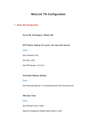
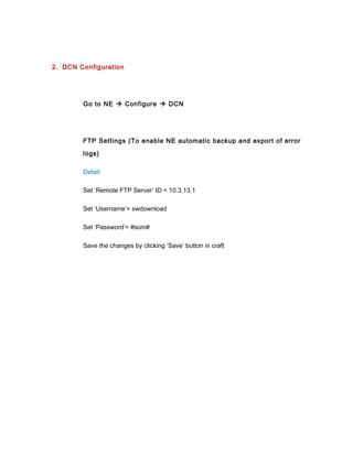


This document provides instructions for configuring a MiniLink TN network including: 1) basic NE configuration like NTP server and backup settings, 2) DCN configuration for automatic backups, 3) radio link configuration such as terminal IDs, transmit power settings, frequencies, and input alarm thresholds, and 4) protection switch configuration for 1+1 links. The steps provided configure settings according to a provided plan and make noted changes where settings do not match what is in the plan.