Downloaded 147 times
![Page 7
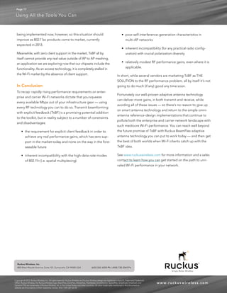
Using All the Tools You Can
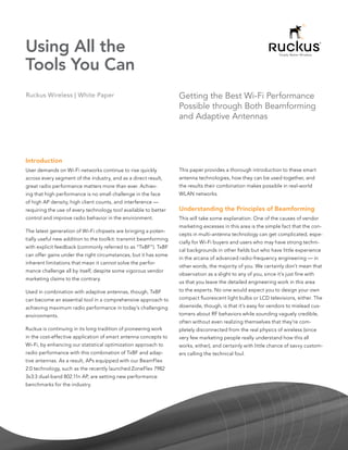
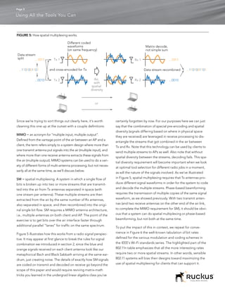
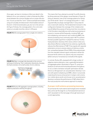
In Contrast: Understanding Adaptive Antennas FIGURE 7: High-level view of Ruckus BeamFlex architecture.
While we often use the term “beamforming” loosely, in the
generic sense of “shaping radio energy in space,” to talk about Off-the-Shelf RF
the variety of multi-antenna processing we have employed in 802.11 Silicon
RF
our APs to date, as a matter of convenience when we don’t
Host MAC PHY RF
want to have a long discussion about distinctions between
n antenna elements
different multi-antenna architectures, that’s not an entirely
accurate term for what we have been doing, given the strict
Better antenna patterns
definition we introduced in section 2. As we illustrate in Figure
The baseline for comparison here is the kinds of beam patterns
7, the approach we’ll call for the moment BeamFlex 1.0 involves
that can be created with phase-based beamforming — illus-
digitally switching a selection from a large number of antenna
trated in Figure 8. This approach is limited to using only as many
elements to connect with the individual radio chains in the RF
antennas as it has radio chains. With only two or three anten-
front end of off-the-shelf Wi-Fi silicon. A “radio chain” is the RF
nas at work, the shapes that can be created are fairly limited in
engineering term for the analog radio part between the chip
structure, and they have consistent characteristics that diminish
doing the digital Wi Fi protocol processing and the antennas.
their utility in practice: they are symmetric, and their lobes or
In BeamFlex 1.0 there is no analog adjustment of phase on
beams tend to be relatively narrow. The symmetry means that
each radio chain. Instead, an optimal combination of antennas
from the perspective of a target client, half the energy transmit-
is selected on a packet-by-packet basis to focus patterns of
ted is wasted. From the vantage point of neighboring APs in
radio energy in the right radio-space ‘direction’ based on the
the WLAN, this energy is worse than wasted — it means louder
inherent characteristics of the antenna elements themselves.
co-channel interference. The narrow widths mean they are
The selection for a given client is based on the throughput last
pretty unforgiving about inaccurately pointed beams. If an AP’s
achieved with that client, confirmed through the ACK packet
estimate of the right phase combination to use for its antennas
that is a standard part of the 802.11a, b, g, and n Wi-Fi proto-
is a little off (either because it was using imperfect implicit feed-
cols and that is supported by all clients today. [Note that some
back, or because the higher-quality explicit feedback forthcom-
vendors attempt to compensate for their lack of intellectual
ing in Wi-Fi systems has gotten out of date because of delays in
property contributions in Wi-Fi by de-positioning BeamFlex
its use, high client mobility, or rapid changes in the environment
as “non-standard” — which couldn’t be further from the truth.
like a door closing), the beam formed will fall where the client
Our APs are absolutely 100% compliant with the 802.11 proto-
isn’t, and an area of destructive combination will fall where the
cols, as proven by the Wi-Fi Alliance certification we receive
client is, making the whole exercise worse than useless.
on every model we sell, and require absolutely zero special
behavior on the part of clients.] With AA, in contrast, highly asymmetric patterns can be
achieved that have much more forgiving lobe shapes, and
Of the many terms used in the general area of multi-antenna
with huge variety across physical as well as polarization space
processing techniques (such as smart antennas, beam switch-
(See Figure 9). Because the n elements of a Ruckus antenna
ing, beamforming, and so on), the most accurate classification
matrix can be switched combinatorially to the radio chains of
of BeamFlex 1.0 would probably be in the category of adap-
a Wi-Fi chipset, the number of possible patterns is 2n. Typical
tive antennas (AA). The statistical optimization engine that AP configurations contain thousands of possible patterns.
powers its superior performance is also managing a number
of other variables at the system level, including rate selection The asymmetry of these patterns provides very significant
and power control, so it is about more than just antenna adap- benefits when you look at a WLAN with many access points.
tation itself, an idea to which we will return in a moment in the As Figure 10 shows, a typical Ruckus AA pattern has as much
context of BeamFlex 2.0. as 10 to 15 dB of inherent self-interference suppression over
more than half of the total coverage area. As a result, Ruckus
There are three primary functional advantages in our ability APs tend to be better neighbors of each other in a network
to use a combination of multiple antennas on individual Wi Fi than is the case for conventional approaches, whether they
radio chains in AA: better antenna patterns, compatibility with using TxBF or simple omni antennas alone.
spatial multiplexing, and more effective support for polariza-
tion diversity. We’ll look at each in turn.
Simply Better Wireless.](https://image.slidesharecdn.com/adaptive-antennas-120605104812-phpapp01/85/Adaptive-Antennas-vs-TxBF-7-320.jpg)
![Page 8
Using All the Tools You Can
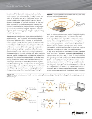
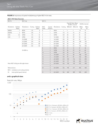
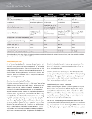
FIGURE 8: Full range of patterns of constructive signal combination that can be achieved through phase-based beamforming, with
two or three transmit antennas in a typical Wi-Fi AP’s configuration (other patterns not shown are simple mirror images of these
across a vertical axis).
Two Antennas
Three Antennas
FIGURE 9: Sample of patterns of constructive signal combination that can be achieved through Ruckus BeamFlex (total variations
available = 2n, where n = the number of elements in the AP’s antenna matrix)
1 2 3 4 5 6 2n
•••
Finally, when combined with TxBF in BeamFlex 2.0, our asym- FIGURE 10: Typical BeamFlex antenna system pattern and
inherent interference reduction.
metric adaptive antenna patterns deliver better client connec-
tions while continuing to reduce self-interference, relative to dBi
10 Client
TxBF operation alone. Figure 11 illustrates how this works. 5
0
Typical
-5
BeamFlex
-10
Pattern
Compatibility with Spatial Multiplexing -15
BeamFlex is the industry’s only multi-antenna approach that -20
-25
can support both spatial multiplexing and constructive signal -30
combination at the same time using only two transmit radio
chains. An example of how this works is shown in Figure 12
10 – 15 db
below. [We’ll note in the interest of full disclosure that it is
interference
technically possible to support the combination of SM and mitigation over more
TxBF on an AP with four radio chains, but that configuration than 180°
is not commercially viable in today’s Wi-Fi market because of
high hardware costs and power requirements beyond the lim-
its of the 802.3af PoE source that is used for the vast majority
of AP installations.]
Simply Better Wireless.](https://image.slidesharecdn.com/adaptive-antennas-120605104812-phpapp01/85/Adaptive-Antennas-vs-TxBF-8-320.jpg)
![Page 14
Using All the Tools You Can
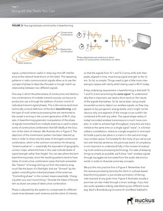
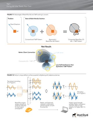
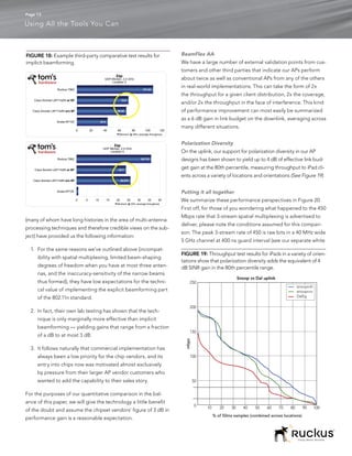
FIGURE 20: Rate and range comparison of various multi-antenna technologies. See text for additional explanatory notes and sources.
RF Technology Comparison
300 DL Throughput, Mbps
[1] 1x1:1 omni
250 [2] 1x1:1 TxBF
[3] 1x1:1 AA+TxBF
[4] 3x3:3 omni
200
[5] 3x3:3+TxBF (for non-SM MCSs)
[6] 3x3:3 AA + TxBF (non-SM)
150
100
50
0
0 10 20 30 40 50 60 70
Range, m
RF Technology Comparison
100 UL Throughput, Mbps
90
[7] 1x1:1 single-polarization MRC
80
70 [8] 1x1:1 polarization-diversity MRC
60
50
40
30
20
10
0
0 10 20 30 40 50 60 70
Range, m
Notes on conditions: 5 GHz, 40 MHz channel, 800 ns guard interval, ETSI EIRP level, UDP traffic,
medium level of Wi-Fi and other interference, near LoS link conditions, indoors.
Simply Better Wireless.](https://image.slidesharecdn.com/adaptive-antennas-120605104812-phpapp01/85/Adaptive-Antennas-vs-TxBF-14-320.jpg)
![Page 15
Using All the Tools You Can
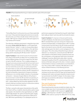
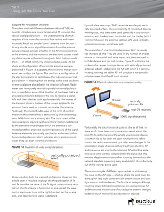
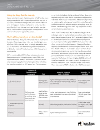
paper Caveat Emptor for more details on translation from [4] DL 802.11n 3x3:3 omni. For this and the next two curves,
peak Wi-Fi claims to real-world usable throughput rates). We we depict system performance with a high-end laptop on the
prefer to frame the analysis in a domain relevant to real-world client side, supporting three spatial streams. The baseline
net usable packet throughput (net of 802.11 protocol over- for this use case is a conventional AP with omni antennas and
head and other factors) for real equipment. So our analysis neither TxBF nor AA. Most of this curve is actually coincident
depicts UDP traffic in 5 GHz, which cuts the peak three-stream with the next curve, [5], for reasons that will become clear in a
rate down from the theoretical maximum of 450 to 272 Mbps. moment. Note the descent of the 3x3 system’s performance as
The other dimension of realism is client to AP range — we’ve a function of range. The higher modulation classes (based on
assumed here ETSI requirements for EIRP (100 mW) and a 64 QAM, a very complex constellation) in combination with 3
healthy dose of interference and fading margin for busy indoor spatial streams are only effective, in practice, at shorter ranges
conditions (15 dB). where there is enough diversity in the signal paths to accu-
rately decode the three streams. Note that the performance
Now to explain each of the curves:
of the 3x3:3 system converges toward that of the 1x1:1 system
[1] DL 802.11n 1x1:1 omni. This is the low water mark, depict- at longer range, as the realities of RF propagation reduce the
ing the kind of performance expected from a conventional ability to achieve SM with reliability even for 2 streams.
omni-equipped AP with no multi-antenna processing, com-
[5] DL 802.11n 3x3:3 + TxBF for non-SM MCSs. As we’ve
municating in downlink (DL) with a single-antenna client like a
noted, TxBF cannot be used simultaneously with SM. One can,
smartphone or a tablet.
however, consider its use for the non-SM MCS rates (0 through
[2] DL 802.11n 1x1:1 + Explicit-Feedback Transmit Beam- 7) in 802.11n, to enhance link budget under conditions (such as
forming. As we explained in section 2, the addition of explicit- low diversity or long range) where SM is not possible. We’ve
feedback beamforming on a conventional 2- or 3-stream AP shown this effect in the right-hand side of curve [5], where it
(the only practical model extant today) provides the system diverges from curve [4]. For speeds above 25 Mbps, roughly,
the choice of using TxBF or spatial multiplexing, but not both SM would be employed and scenario [4] and [5] are the same.
at the same time. With only 3 dB of incremental gain to offer,
[6] DL 802.11n 3x3:3 + BeamFlex 2.0. This adds BeamFlex
TxBF does not provide enough of a performance benefit to
AA gains on top of the SM-based rates in a 3-stream 11n chan-
outweigh the data rate gains from SM in any case other than
nel along with TxBF gains for the non-SM MCSs on the right
that for which SM is not an option, the 1x1:1 system. As can
end of the chart. As with curve [3], the advantages in through-
be seen, 3 dB doesn’t buy a lot, in terms of either throughput
put at a given range driven by BeamFlex AA technology
increases or range extension — roughly a 30% increase.
remain quite substantial.
[3] DL 802.11n 1x1:1 with Adaptive Antennas + TxBF
[7] UL 802.11n 1x1:1 Single-Polarization MRC. This depicts
(BeamFlex 2.0). Here we apply both adaptive antennas and
the baseline performance in uplink from a single-antenna
TxBF to a single-stream client, yielding a 2x or better improve-
smart mobile device to a 3-antenna AP performing conven-
ment in range or capacity from the combination.
tional MRC processing, assuming all 3 antennas have the same
This reflects the two spatial streams performance of an AP polarization.
equipped with 2 omni antennas communicating with a 2 Rx
[8] UL 802.11n 1x1:1 Polarization-Diversity MRC. Finally, we
equipped client such as a laptop. Note that the performance
depict the results of introducing BeamFlex adaptive polariza-
of the 2x2:2 system converges to that of the 1x1:1 system at
tion on the multi-antenna AP Rx side, which allows polarization-
longer range, as the realities of RF propagation reduce the
diversity MRC (PD MRC) processing and yields around 4 dB of
ability to achieve spatial multiplexing with reliability. The per-
effective SINR improvement. As the curve shows, this can yield
formance of an AP with implicit or explicit beamforming capa-
substantial (~2x) improvements in client throughput on uplink,
bilities would look exactly the same as this curve, because of
which is commonly the limiting metric for network dimension-
the mutual exclusivity of spatial multiplexing and phase-based
ing in today’s user-generated-content-rich application environ-
beamforming.
ment and therefore an extremely valuable improvement.
Simply Better Wireless.](https://image.slidesharecdn.com/adaptive-antennas-120605104812-phpapp01/85/Adaptive-Antennas-vs-TxBF-15-320.jpg)

This white paper discusses the integration of beamforming and adaptive antenna technologies to enhance Wi-Fi performance in high-density environments. It explains the principles of transmit beamforming with explicit feedback and adaptive antennas, emphasizing their combined role in optimizing radio behavior and overcoming challenges such as interference. The document also addresses misconceptions in vendor marketing related to multi-antenna technology, offering insights for better Wi-Fi network design based on fundamental RF concepts.


![Mimo [new]](https://cdn.slidesharecdn.com/ss_thumbnails/mimonew-150914045107-lva1-app6892-thumbnail.jpg?width=640&height=640&fit=bounds)


![5G Explained! A High Level Overview [Introduction]](https://cdn.slidesharecdn.com/ss_thumbnails/5gexplainedahighleveloverview-260119165306-cc137a3e-thumbnail.jpg?width=640&height=640&fit=bounds)


