The document discusses a proposed technique for reducing the Peak to Average Power Ratio (PAPR) in multicarrier code division multiple access (MC-CDMA) systems by using inverse discrete transforms and a modified exponential companding with clipping transform (MECCT). It analyzes the performance of this technique over various mobile radio channels, including additive white Gaussian noise and multipath fading channels. The study compares PAPR and bit error rate (BER) performance of the system utilizing different transform methods to highlight potential improvements in power efficiency and signal quality.
![Discrete Transforms based MC-CDMA PAPR
Reduction using MECCT and Bit Error Rate
Performance Analysis over Mobile Radio Channels
B.Sarala1
, D.S.Venketeswarlu2
, B.N.Bhandari3
and B.Srinivas4
1
M V S R Engg. College, ECE Dept., Hyderabad, AP, India. b.sarala@rediffmail.com
2
Progressive Engg. College, ECE Dept., , Hyderabad, AP, India. dsv4940@gmail.com
3
JNTU, ECE Dept., Hyderabad, AP, India. bnb@ieee.org
4
M V S R Engg. College, ECE Dept., Hyderabad, AP, India. bsrinivas.mvsr@gmail.com
Abstract— A significant problem in Multicarrier Code Division Multiple Access (MC-
CDMA) system is the possibility of high Peak to Average Power Ratio (PAPR). This is due
to the cumulative sum of N subcarrier peaks in the transmitted signals which reduces Power
efficiency, resolution and battery life. In this paper a technique is proposed to make use of
Inverse Discrete Cosine Transform (IDCT) and Inverse Discrete Wavelet Transform
(IDWT) based Multicarrier Code Division Multiple Access (MC-CDMA) system. This
system is in combination with Modified Exponential Companding with Clipping Transform
(MECCT) technique which reduces PAPR and that is analyzed over Additive White
Gaussian Noise (AWGN) channel, Rayleigh and Stanford University Interim (SUI)
multipath fading channel.
Index Terms— MC-CDMA, PAPR, companding, MECCT, FFT, DWT, DCT, Fading
channel.
I. INTRODUCTION
One of the challenging issues in MC-CDMA system is high PAPR. Literature survey includes review and
analysis of different MC-CDMA PAPR reduction techniques based on computational complexity, bandwidth
expansion, spectral spillage performance and memory requirements etc. There has been a lot of research
work done on PAPR reduction techniques in Multi-carrier Modulation (MCM) systems. Several techniques
are proposed for PAPR reduction. Signal distortion techniques including clipping, clipping and filtering,
windowing, peak cancelling. Signal pre-distortion techniques based on companding to reduce the PAPR have
been proposed by several authors using different companding techniques such as µ-Law, exponential, and
linear. In companding technique, compression in transmitter and expansion in receiver has been introduced
by Wang et al [1].
In a wireless communication link the signal quality is degraded by multipath fading and by addition of noise
during its propagation to the receiver. The channel itself behaves as a system with its own impulse response
and acts on the signal propagating in a decreasing manner.
Hence, there arises the necessity to model the channel by estimating its impulse response so that an inverse
system corresponding to it is designed and placed at the front end of the receiver to counteract the channel
system transform. This idea can be implemented for any channel and a variety of wireless communication
DOI: 02.ITC.2014.5.571
© Association of Computer Electronics and Electrical Engineers, 2014
Proc. of Int. Conf. on Recent Trends in Information, Telecommunication and Computing, ITC](https://image.slidesharecdn.com/571-238-247-140325035614-phpapp01/85/571-238-247-1-320.jpg)
![Discrete Transforms based MC-CDMA PAPR
Reduction using MECCT and Bit Error Rate
Performance Analysis over Mobile Radio Channels
B.Sarala1
, D.S.Venketeswarlu2
, B.N.Bhandari3
and B.Srinivas4
1
M V S R Engg. College, ECE Dept., Hyderabad, AP, India. b.sarala@rediffmail.com
2
Progressive Engg. College, ECE Dept., , Hyderabad, AP, India. dsv4940@gmail.com
3
JNTU, ECE Dept., Hyderabad, AP, India. bnb@ieee.org
4
M V S R Engg. College, ECE Dept., Hyderabad, AP, India. bsrinivas.mvsr@gmail.com
Abstract— A significant problem in Multicarrier Code Division Multiple Access (MC-
CDMA) system is the possibility of high Peak to Average Power Ratio (PAPR). This is due
to the cumulative sum of N subcarrier peaks in the transmitted signals which reduces Power
efficiency, resolution and battery life. In this paper a technique is proposed to make use of
Inverse Discrete Cosine Transform (IDCT) and Inverse Discrete Wavelet Transform
(IDWT) based Multicarrier Code Division Multiple Access (MC-CDMA) system. This
system is in combination with Modified Exponential Companding with Clipping Transform
(MECCT) technique which reduces PAPR and that is analyzed over Additive White
Gaussian Noise (AWGN) channel, Rayleigh and Stanford University Interim (SUI)
multipath fading channel.
Index Terms— MC-CDMA, PAPR, companding, MECCT, FFT, DWT, DCT, Fading
channel.
I. INTRODUCTION
One of the challenging issues in MC-CDMA system is high PAPR. Literature survey includes review and
analysis of different MC-CDMA PAPR reduction techniques based on computational complexity, bandwidth
expansion, spectral spillage performance and memory requirements etc. There has been a lot of research
work done on PAPR reduction techniques in Multi-carrier Modulation (MCM) systems. Several techniques
are proposed for PAPR reduction. Signal distortion techniques including clipping, clipping and filtering,
windowing, peak cancelling. Signal pre-distortion techniques based on companding to reduce the PAPR have
been proposed by several authors using different companding techniques such as µ-Law, exponential, and
linear. In companding technique, compression in transmitter and expansion in receiver has been introduced
by Wang et al [1].
In a wireless communication link the signal quality is degraded by multipath fading and by addition of noise
during its propagation to the receiver. The channel itself behaves as a system with its own impulse response
and acts on the signal propagating in a decreasing manner.
Hence, there arises the necessity to model the channel by estimating its impulse response so that an inverse
system corresponding to it is designed and placed at the front end of the receiver to counteract the channel
system transform. This idea can be implemented for any channel and a variety of wireless communication
DOI: 02.ITC.2014.5.571
© Association of Computer Electronics and Electrical Engineers, 2014
Proc. of Int. Conf. on Recent Trends in Information, Telecommunication and Computing, ITC](https://image.slidesharecdn.com/571-238-247-140325035614-phpapp01/75/571-238-247-1-2048.jpg)
![239
receivers. The MC-CDMA system promises high speed, large bandwidth, and better frequency diversity in
multipath wireless communication system. The channel may introduce fading and noise to the propagating
signal and is responsible for distorting the signal by having a channel estimation filter section at the receiver;
we can nullify the effects of the channel on the signal, while designing a mobile radio channel to meet the
design constraints on power, bandwidth, complexity and cost. It can also satisfy throughput and quality of
service.
MC-CDMA by its frequency diversity is an attractive modulation method for multi-user high data rate
wireless communication system. In this system, data symbols consisting of binary information bits are
usually first spread by orthogonal codes and then modulated and mapped into subcarriers of an Orthogonal
Frequency Division Multiplexing (OFDM) modem in such a way that the data symbol is spread across the
frequency domain. MC-CDMA signal consists of n data symbols transmitted over Nc subcarriers from an Nc -
IFFT operation and generates Nc complex numbers. MC-CDMA is used in physical layer of Wireless Local
Area Network (WLAN), Long Term Evolution (LTE) and 4th
generation wireless networks. These schemes
use Fast Fourier Transform FFT) to generate orthogonal subcarriers [2]. These systems use complex
exponential functions set as orthogonal basis that can be used to construct baseband signals of MC-CDMA
system. In this paper, Discrete Cosine Transform (DCT) functions/ discrete wavelet functions has been used
to construct baseband signals of MC-CDMA system and compared with the FFT based MC-CDMA system.
In general the PAPR of the MC-CDMA signal x(t) is defined as the ratio between maximum instantaneous
power and its average power during the MC-CDMA signal is shown in equation (1) [3 ,4 and 5].
PAPR =
P
P
= 10log
max[|x(t)| ]
E[|x(t)| ]
dB (1)
Multi-Carrier Modulation (MCM) is a technique for data transmission by dividing a high-bit rate data stream
into several parallel low-bit rate data streams to modulate several subcarriers. Based on Previous research,
the method for generating a MCM symbols by the N input complex symbols padded with zeroes to get N
symbols these are used to calculate the Inverse Fast Fourier transform (IFFT). The output of IFFT is the basic
MCM symbol. The objective of this paper is to generate Multi-Carrier Modulated symbol by replacing IFFT
with Inverse Discrete Wavelet Transform (IDWT) or Inverse Discrete Cosine Transform (IDCT) in
combination with the MECCT. It is used to reduce PAPR and also to study and investigate over mobile radio
channels such as Additive White Gaussian Noise (AWGN) / Rayleigh fading channel /Stanford University
Interim (SUI) channel.
This paper also compares the PAPR and Bit Error Rate (BER) performance of Inverse Fast Fourier
Transform (IFFT)/ Inverse Discrete Cosine Transform (IDCT)/ Inverse Discrete Wavelet Transform (IDWT)
based MC-CDMA with MECCT. The rest of the paper is organized as follows: Section II describes
IFFT/IDWT/IDCT based MC CDMA system. In Section III related works are presented. In section IV
MECCT companding and de-companding algorithms are discussed. In section V discusses AWGN/Rayleigh
/SUI fading channels. In section VI computer simulations are discussed. In section VII conclusions and
future work are listed.
II. MC-CDMA SYSTEM
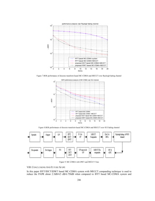
Figure (9) shows that the user data is applied to spreader then its output is applied to Binary Phase Shift
Keying (BPSK) modulator, which generates real and imaginary components. The spread symbols are applied
to Serial to Parallel (S/P) converter and modulated by IFFT/ IDCT or IDWT based multicarrier modulation.
Multicarrier modulator output is fed to the parallel to serial (P/S) converter and Cyclic Prefix block (CP)/
guard insertion block to eliminate Inter Symbol Interference (ISI) and fed to MECCT companding block. The
sequence is passed through a Digital to Analog Converter (DAC) and High Power Amplifier (HPA). The
signal is up converted and transmitted through AWGN channel/Rayleigh and SUI fading channels.
At the receiver, by using a guard interval removal at the receiver chooses that portion of the signal, which is
free from ISI. The output of the channel, after Radio Frequency (RF) down conversion, the received signal
wave is y(t) obtained from convolution of transmitted signal x(t) with the channel impulse response h( ,t)
and addition of AWGN/Rayleigh/SUI fading channels. The received signal is fed to the matched filter and
Analog to Digital Converter (ADC). This is Processed by MECCT de-companding block and converted into
serial to parallel converter and then fed to Fast Fourier Transform (FFT)/ Discrete Cosine Transform (DCT)/
Discrete Wavelet Transform (DWT) block to demodulate several subcarriers. The FFT/DCT/DWT output fed](https://image.slidesharecdn.com/571-238-247-140325035614-phpapp01/85/571-238-247-2-320.jpg)
![240
to demodulator, which demodulates the BPSK signal and then de-spreads the code synchronization to
accomplish completely for the first path of desired signal [2 and 3].
III. DISCRETE FOURIER TRANSFORM BASED MC-CDMA
A. Fourier Transforms (FFT/IFFT)
To generate multicarrier modulation for MC-CDMA system using IFFT, the relation between all the
subcarriers must be orthogonal to each other. MC-CDMA symbol generated by spectrum is required based on
the input data, modulation scheme used and each carrier with assigned data to transmit. The required
amplitude and phase of the carrier is then calculated based on type of Phase Sift Keying (PSK). To generate
the multiple orthogonal subcarrier signals, which are overlapped in spectrum to appear N point IFFT of the
transmitted symbols. Thus an MC-CDMA symbol is generated by computing IFFT of the complex
modulation symbols to be communicated in each subcarrier.
The receiver will receive a signal degraded by AWGN. Taking N-point FFT of the received samples the
noisy version of transmitted symbols can be obtained in the receiver. The spectrum of the MC-CDMA signal
can be measured as the sum of frequency shifted sinc functions in the frequency domain. As all the
subcarriers are of the finite duration and the signal generated is a RF baseband signal, has to be filtered and
mixed to the preferred transmission frequency.
The sequence of N complex numbers x0, -----,xN-1 is transformed into the sequence of N complex numbers
X0,--------,XN-1 synthesized by the Inverse Fast Fourier Transform(IFFT). This is given by the equation (2)
x(n) =
1
N
X(k) e , n = 0, −−, N − 1 . (2)
Where ( ) describes the signal after subcarrier mapping and N is the IFFT length. The Fast Fourier
transform (FFT) is given by equation (3)
X(k) = x(n) e /
,k = 0, − − −, N − 1 (3)
Where n = 0, -----N-1. The complex numbers x(n) distinguish the amplitude and phase of the different
sinusoidal components of input signal X(k). The FFT converts x(n) to X(k)and IFFT converts X(k) to x(n)by
to compute the x(n) as a sum of sinusoidal components (1/N) X(k) /
with frequency K/N cycles per
sample. The FFT at the receiver transforms the received signal to the frequency domain in order to recover N
subcarriers [6 and7].
B. Discrete Cosine Transforms (DCT/IDCT)
In Discrete Cosine Transform (DCT) based Multicarrier Code Division Multiple Access system (MC-
CDMA) system uses instead of IFFT of complex exponential functions, cosine functions are synthesized by
Inverse Discrete transform (IDCT) are used as orthogonal basis to implement MC-CDMA system symbols. A
single co-sinusoidal functions set cos 2 ∆ will be used as the orthonormal basis to implement MC-
CDMA symbols. The minimum ∆ required to satisfy equation (4) is 1/2T.
b(k) =
1
√N
, for k = 0 ,
2
N
, for k ≠ 0 (4)
The IDCT based MC-CDMA system can be written as in equation (5).
x(n) = (k) X(K)cos
π(2n + 1)K
2N
(5)
for K = 0, −, N − 1
Where X0, ----, XN-1 independent data symbols obtained from a IDCT output.
At the receiver the Discrete Cosine transform (DCT) is given by equation (6)
X(K) = ( ) (k) cos
(2 + 1)
2
(6)
= 0, … , − 1
In DCT-MC-CDMA system the signal energy is concentrated in a few low index coefficients, while the
remaining coefficients are zero or negligibly small.](https://image.slidesharecdn.com/571-238-247-140325035614-phpapp01/85/571-238-247-3-320.jpg)
![242
x(t) =
1
N
S e ,0 ≤ t (11)
The Nc subcarrier frequencies are given in equation (12).
= , = 0, … . , − 1 (12)
The FFT output sequence of MC-CDMA receiver system Rl, l = 0,…. − 1 consisting of complex
valued symbols as represented in equation (12).
= /
, = 0,… , − 1 (13)
The received symbol Rl is obtained from the frequency domain representation in equation (14) as shown
below.
= + , = 0,… . , − 1 (14)
Hl = Flat fading factor, Nl = The noise of the lth
subcarrier.
The IDCT/IDWT and DCT/DWT expressions are given in reference paper [6and7].
IV. RELATED WORK
Earlier we proposed the method-I was the technique for the use of DCT/DWT in combination with µ-Law
companding in order to achieve a very substantial reduction in PAPR of the MC CDMA signal. In this
scheme, in the first step, the data is transformed by a Discrete Cosine Transform (DCT) or Discrete Wavelet
Transform into new modified data. In the second step, this scheme also uses the companding technique
further to reduce the PAPR of the MC CDMA signal [8]. We proposed the method-II was the IFFT based
MC-CDMA with MECCT technique, the PAPR is reduced by 2.0 dB and also BER improved for AWGN
channel [9].
This paper proposes with the use of IDCT/IDWT to generate Multi-Carrier Modulated symbol by replacing
IFFT. IDCT/IDWT based MC-CDMA in combination with MECCT companding is analyzed over mobile
radio channels (AWGN/Rayleigh/SUI fading channel). In this proposed scheme, in the first step, the data is
transformed by an IDCT/IDWT based MC-CDMA signals. In the second step, the proposed technique
employs the MECCT companding technique to reduce the PAPR of the MC CDMA signal. This paper has
compared performance of the PAPRs; BERs for IFFT/IDCT/IDWT based MC CDMA system with MECCT
companding
V. MECCT COMPANDING AND DE-COMPANDING ALGORITHM
The proposed MECCT companding and Decompanding algorithms are given below. The companding
transformation is applied at the transmitter and at the receiver, the de-companding algorithm is applied
through the inverse companding function in order to pick up the original signal.
MECCT Companding Algorithm as given below;
Step1: Calculate threshold value at the transmitter is given by
=
(| |)
(15)
is a variance,
| | is modulus of the MC-CDMA transmitted symbol, is the threshold value.
Step2:
= + log(| | − + 1) (16)
Step3: = , ℎ 0 ≤ | | ≤
, ℎ | | > (17)
Step4: = | | (18)
When =tan and is in the form of a + jb
At the receiver, the inverse companding transform operates on the received signal to obtain an estimation of
the transmitted signal. The MECCT de-companding algorithm as given below;
Step1: Calculate threshold value at the receiver is given by](https://image.slidesharecdn.com/571-238-247-140325035614-phpapp01/85/571-238-247-5-320.jpg)
![243
=
(| |)
(19)
is a variance,
| | Is modulus of MC-CDMA received symbol, is the threshold value at the receiver.
Step2: = − 1 + 10(| | )
(20)
Step3: When =tan and is in the form of
ar + jb (21)
Step4: The original received signal after de-companding
= , ℎ | | ≤
, ℎ | | > (22)
VI. MOBILE RADIO CHANNELS
A. Additive White Gaussian Noise (AWGN) Channel
White noise is due to thermal resistors; many other types of noise sources are Gaussian and have a flat
spectral density over a wide range of frequencies. Desired signal is degraded by thermal noise associated
with the physical channel. To construct a mathematical model for the signal at the input of the receiver, the
channel is corrupted by AWGN ( ) = ( ) + ( ) (23)
Where s(t) is the transmitted signal, n(t) is the sample function of AWGN, r(t) is the received signal.
Therefore, the revised output data after contamination from noise with a power of npow becomes
iout(t) = idata(t) + attnxrandn(t) (24)
qout(t) = qdata(t) + attnxrandn(t) (25)
attn =
1
2
npow (26)
B. Rayleigh fading Channel
Rayleigh fading refers to multiple indirect paths between transmitter and receiver and no distinct dominant
paths (no Line of site path), performance characteristics can be changed for different environments. It is used
in outdoor environment and larger cells. The probability density function of a Rayleigh fading channel is
defined as follows
( ) = −
2
(27)
From this equation, the envelope fluctuation follows a Rayleigh distribution and the phase fluctuation follows
uniform distribution on the fading in the propagation path.
C. Stanford University Interim Channel(SUI)
SUI channels are used for fixed wireless and broadband applications. It is a set of six channels used to
simulate for IEEE 802.16 channel models. They are proposed for a three terrain type’s, type A, SUI-5 and
SUI-6 channels are hilly terrain with moderate to heavy tree densities for terrain type B; SUI-3 and SUI-4
channels are hilly terrain with light tree densities or Flat terrain with moderate to heavy tree densities. For
terrain type C, SUI-1, SUI-2 channels are flat terrain with light tree densities. The set of SUI channel models
state statically constraints of microscopic outcomes such as tapped delay, fading, antenna diversity and
combined with macroscopic channel effects such as path loss and shadowing. It covers the cell size is 10 km.
The BS antenna height 30m, the receiver antenna is 6m; the BS antenna beam width is 120 degree. The
receiver antenna is either Omni directional or directional (30 degrees), and only vertical polarization is used.
Each modified SUI model has three taps. Each tap is characterized by a relative delay, a relative power, a
Rician K-factor, and a maximum Doppler shift. Two sets of relative powers are specified for each channel
model, one for Omni directional antenna, and one for directional antenna. Furthermore, for each set of
relative powers, two k-factors for 90% cell coverage and a k factor for 75% cell coverage [10].
VII. SIMULATION RESULTS
IFFT/IDCT/IDWT based MC-CDMA systems and MECCT companding is implemented using MATLAB
with the following specifications: number of symbols are 256, IFFT size is 256, and number of subcarriers 64
and 128, Walsh Hadamard/Gold/Pseudo Noise (PN) spreading codes and modulation used Binary Phase Sift](https://image.slidesharecdn.com/571-238-247-140325035614-phpapp01/85/571-238-247-6-320.jpg)
![244
Keying (BPSK). This paper evaluates the performance of PAPR using complementary cumulative
distribution of discrete transform based MC-CDMA and companding technique. The results are compared
with different discrete transforms such as IFFT/IDCT/IDWT based MC-CDMA system with MECCT
companding.
SUI-3 channel parameters are power in each tap in dB p=[0 -5 -10]; Rician K-factor in linear scale k=[ 1 0
0]; tap delay in µs tau=[0.0 0.5 1.0]; Doppler maximal frequency parameter in HZ Dop=[0.4 0.4 0.4];
envelope correlation coefficient =0.4; gain normalization factor in dB=-1.5113.
Figure 3. Discrete Transform based MC-CDMA and MECCT nsym=1024; nfft=256; nsub=64
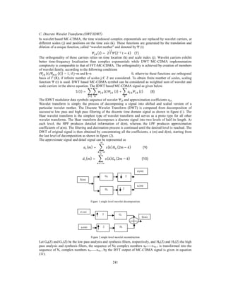
Figures 3 and 4 shows that discrete transforms based MC-CDMA and MECCT PAPRs are measured at
CCDF 10-2
. Discrete Transform based MC-CDMA with MECCT Performance comparison of PAPR
reduction in db, crest factor and BERs are given in table1.The table 1 shows that IDWT based MC-CDMA
with MECCT system is subsequently reduced by 6.75/4.25/2.25 dB when compared to IFFT based MC-
CDMA/ IFFT based MC-CDMA with MECCT/ IDCT based MC-CDMA with MECCT.
Figure 4. Discrete Transform based MC-CDMA with different companding methods; nsym=1024, nfft=256, nsub=128
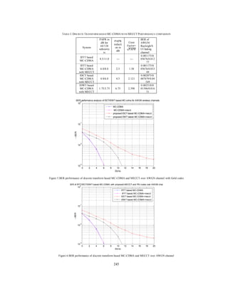
Figures 5 and 6 show that MC-CDMA and MECCT companding method BER is less and Eb/N0 is reduced to
3.0dB when compared with the IDWT based MC-CDMA with MECCT system. IDCT based MC-CDMA
with MECCT requires more bandwidth when compared to the IFFT/IDWT based MC-CDMA with MECCT
and MC-CDMA (original) systems. IDWT based MC-CDMA at Eb/N0 is more than 9 dB is less when
compared to IDCT based MC-CDMA with MECCT.
Figure 7 Shows that BERs of discrete transform based MC-CDMA and MECCT with Rayleigh fading
channel are given in table1.IDCT based MC-CDMA has less BER when compared to the IFFT/IDWT based
MC-CDMA with MECCT.
Figure 8 Shows that BERs of discrete transform based MC-CDMA and MECCT over SUI fading channel are
given in table1.IDWT based MC-CDMA has less BER when compared to the IFFT/IDCT based MCCDMA.
0 2 4 6 8 10 12 14 16 18
10
-2
10
-1
10
0
--PAPR0
--CCDF
PAPR of MC-CDMA with a proposed mecct companding with GOLD codes
IFFT based MC-CDMA
IFFT based MC-CDMA+mecct
Proposed IDCT based MC-CDMA+mecct
proposed IDWT-db4 based MC-CDMA+mecct
0 2 4 6 8 10 12 14 16 18
10
-2
10
-1
10
0
--PAPR0
--CCDF
PAPR of MC-CDMA with a newly proposed mecct companding with GOLD codes
IFFT based MC-CDMA
IFFT based MC-CDMA+mecct
Proposed IDCT based MC-CDMA+mecct
proposed IDWT-db4 based MC-CDMA+mecct](https://image.slidesharecdn.com/571-238-247-140325035614-phpapp01/85/571-238-247-7-320.jpg)
![247
decrease the BER over conventional techniques, and improve the power efficiency. The discrete based MC-
CDMA BER is analyzed over AWGN channel and Rayleigh /SUI fading channels.
This research will continue in PAPR reduction of MC-CDMA by improved performance, low data rate loss,
and less complexity and efficient use of the channel. Further it is implemented with the various
multiresolution wavelets.
REFERENCES
[1] S.H.Han and J.H.Lee, (2005) “An overview of Peak to average Power Ratio reduction techniques for multicarrier
transmission”, IEEE Wireless Communication Magazine, Vol.12, No.2, pp 55-65.
[2] Hara, S. Prasad R.Overview of multicarrier CDMA, IEEE communications Magazine. Dec 1997, Vol.35, no.12, PP
126 – 133.
[3] T.Jiang et.al (2004)”Nonlinear companding transform for reducing peak to average power ratio of OFDM signals”,
IEEE Transactions Broadcast, Vol 50, no.3, 342-346.
[4] T.Jiang et.al (2005)”Exponential companding technique for PAPR reduction in OFDM signals,” IEEE Transactions
Broadcast, Vol.51, no.2, pp244-248.
[5] Suleiman A.Aburakhia, Ehab F.Bardan, and Darwish A.E Mohamed (2009) “Linear Companding Transform for the
Reduction of Peak-to-Average Power Ratio of OFDM signals” IEEE Transactions Broadcast, Vol.55,no.1,pp 155-
160.
[6] “Comparison of DCT and Wavelet Based OFDM System Working in 60 GHZ Band” by Achala Deshmukh and
Shrikant Bodhe IJoAT, vol.3, no.2,April 2012.
[7] “C35.Wavelet-Based SC-FDMA” by M.A. Abd El-Hamed et.al in 29th
National Radio Science Conference (NRSC
2012). April 10-12, 2012.@2012 IEEE.
[8] B.Sarala et.al (2011) “MC CDMA PAPR Reduction Techniques using Discrete Transforms and Companding”,
IJDPS Nov.2011, Vol.2, No.6, PP 253-270.
[9] “MC-CDMA PAPR Reduction Using a Modified Exponential Companding Transform with clipping” B.Sarala et.al
at Global Journals Research in Engineering, volume 13, issue 10, version 1.0, year 2013.
[10] “Simulating the SUI channel models” by Daniel S.Baum, Stanford University, IEEE 802.16.3c-01/53, 2001-04-12.](https://image.slidesharecdn.com/571-238-247-140325035614-phpapp01/85/571-238-247-10-320.jpg)