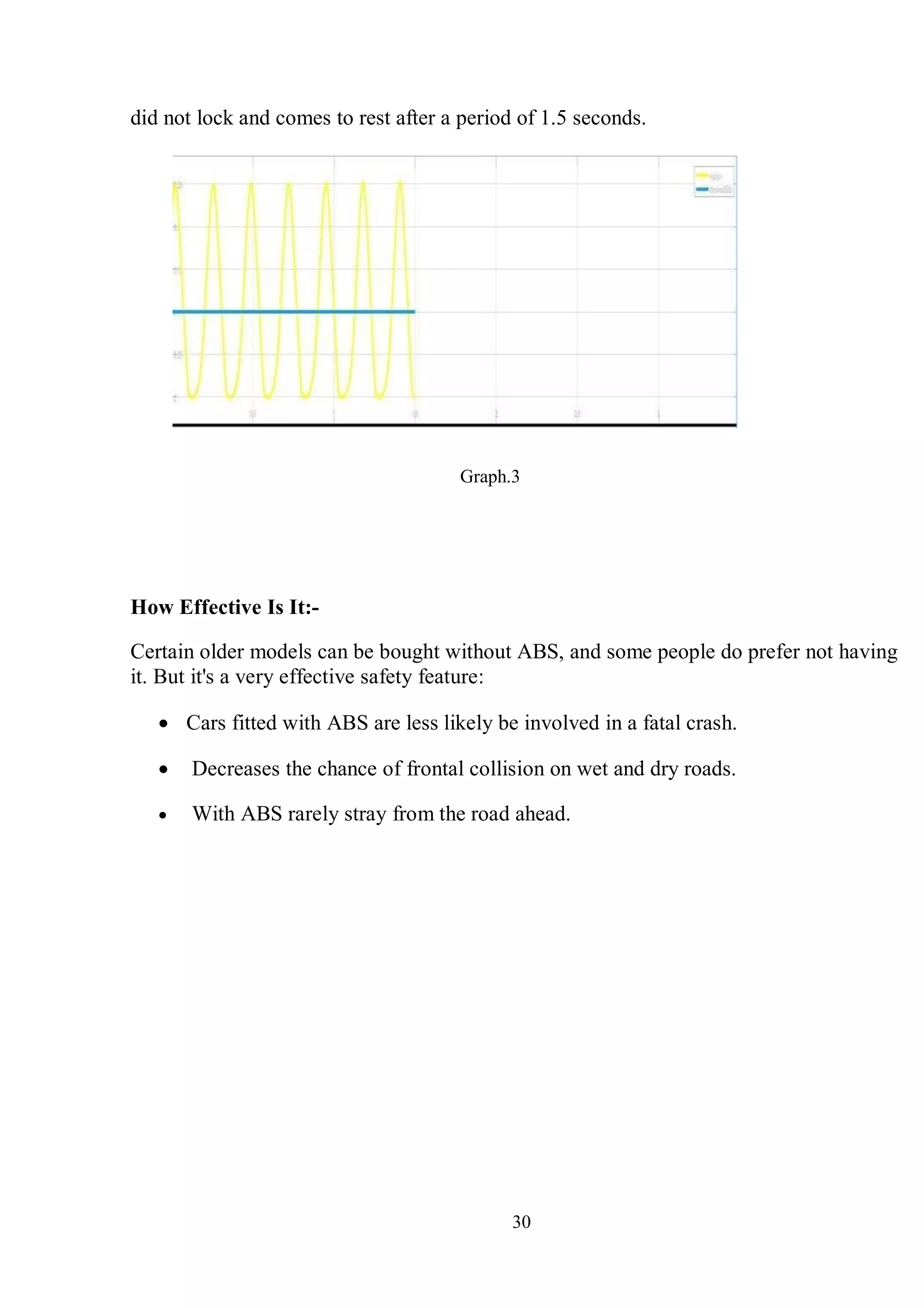
Download to read offline
![35
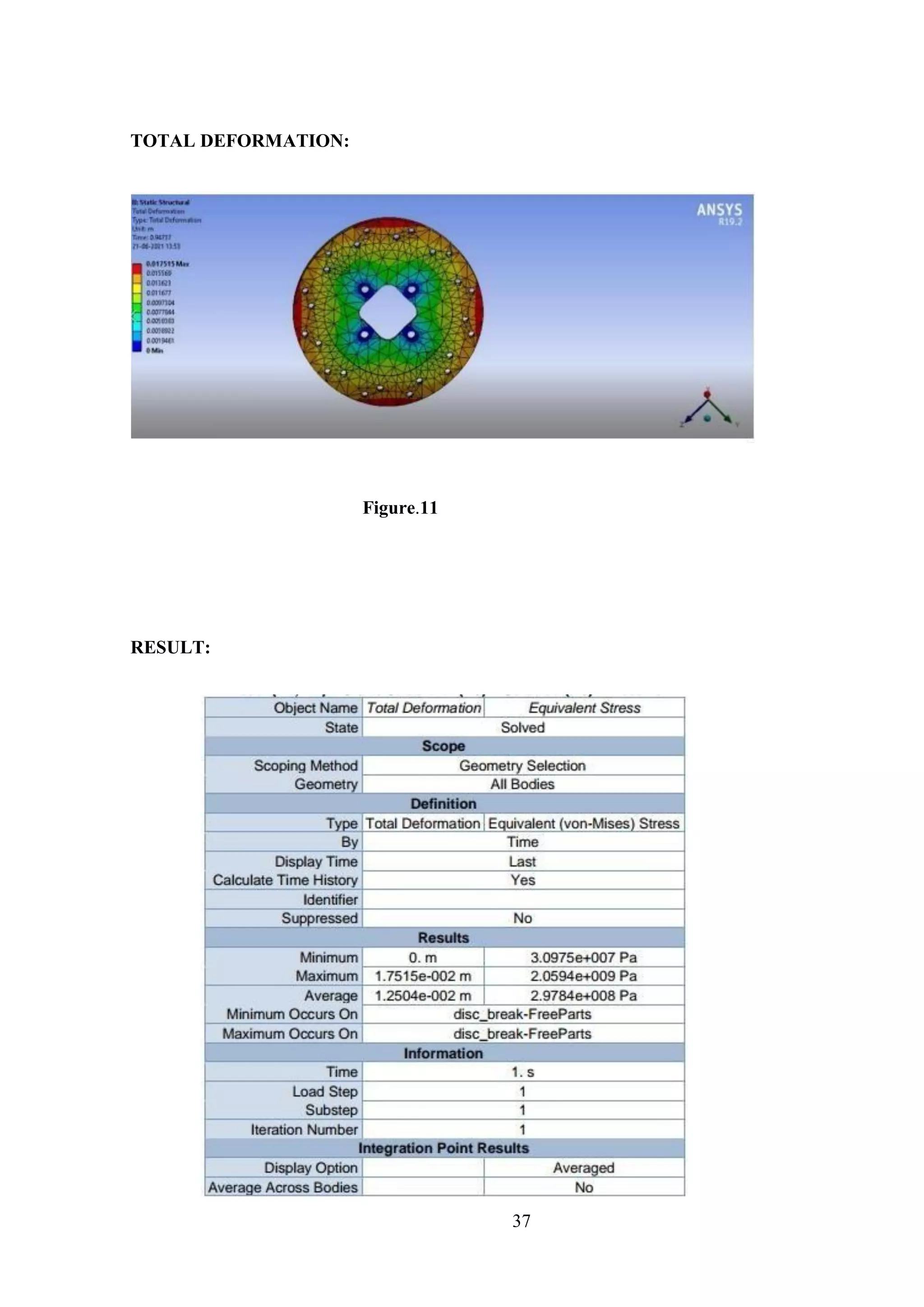
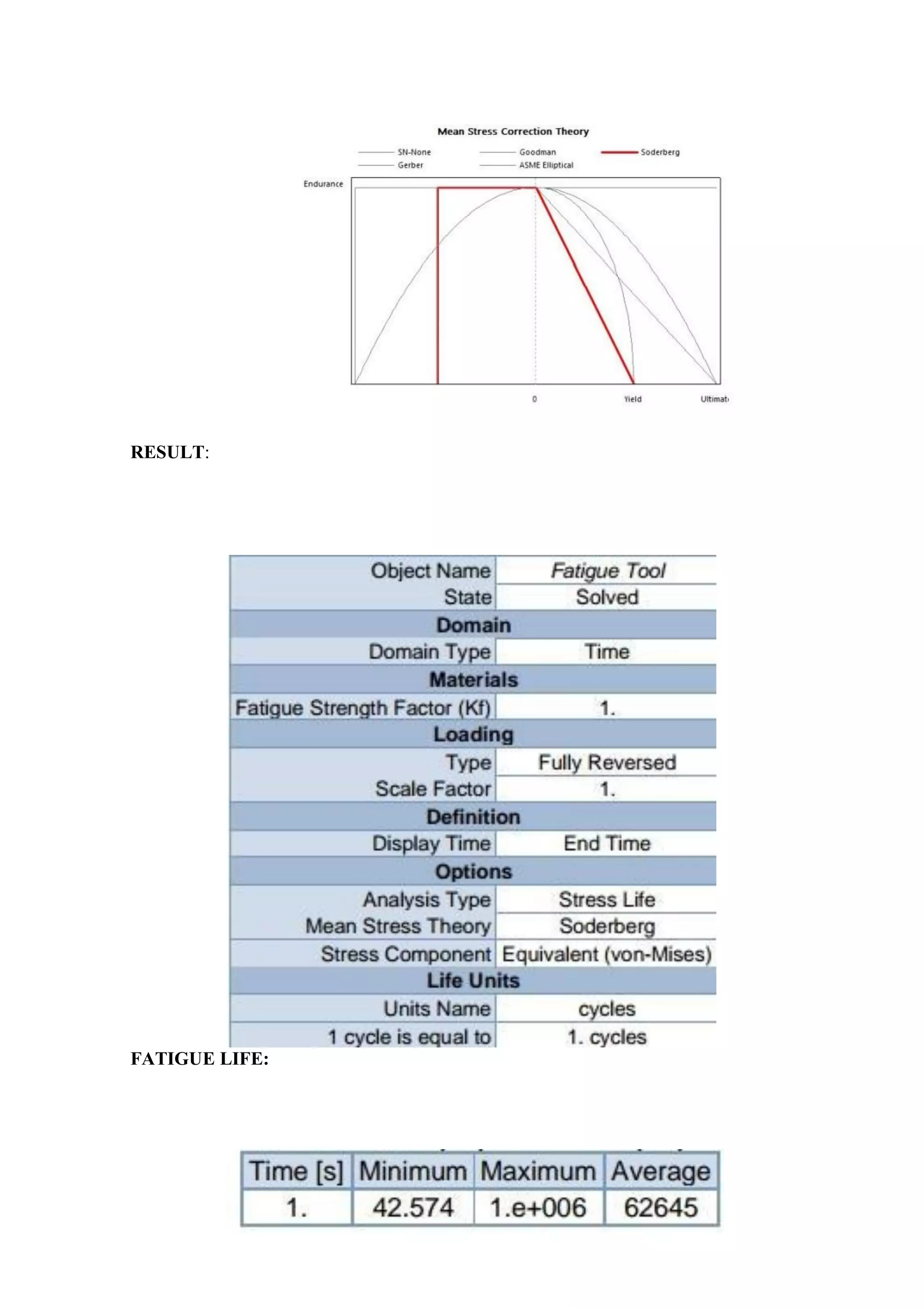
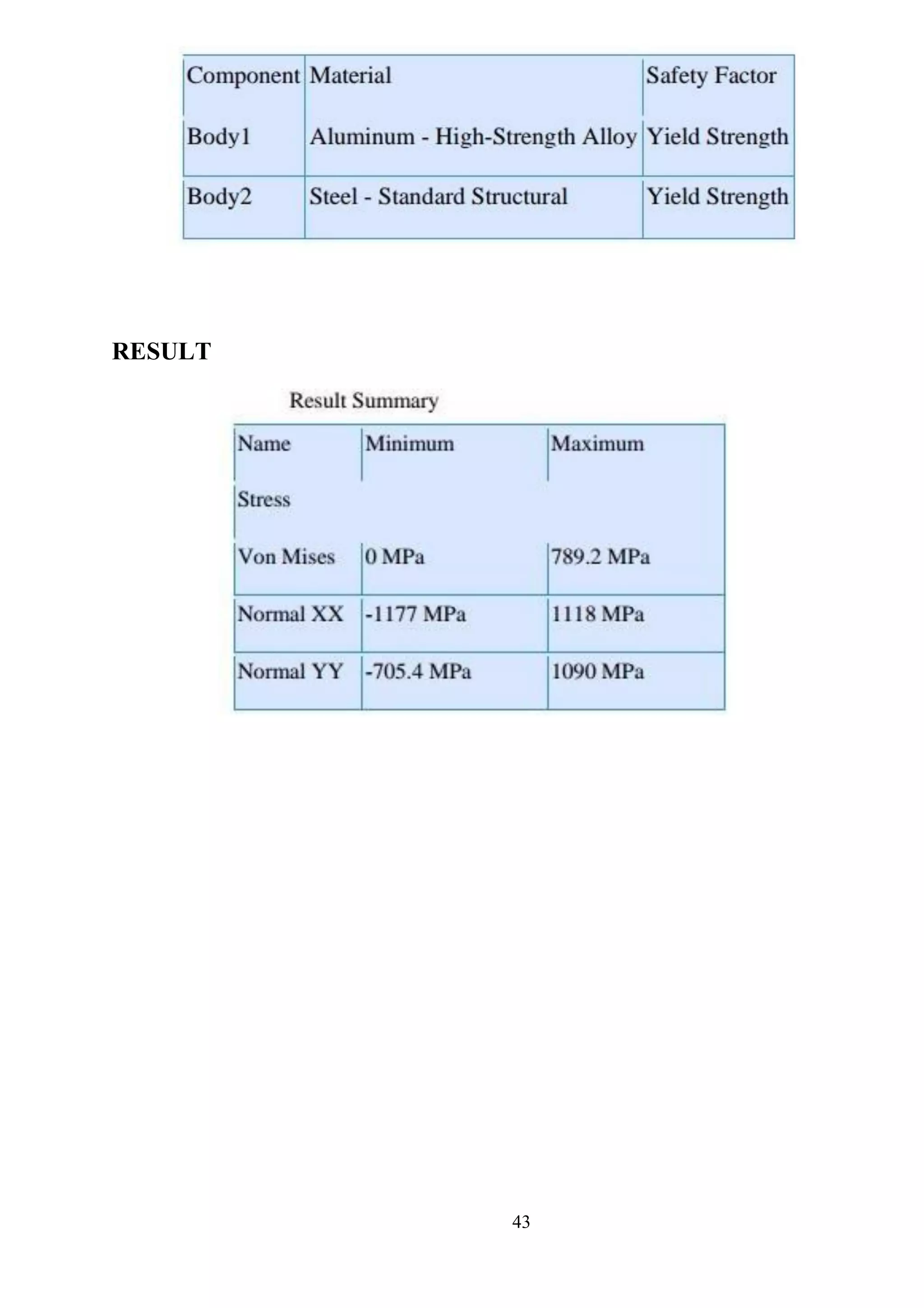
RESULT:
Time [s] Minimum [°C] Maximum [°C] Maximum [°C]
1. 211.16 300 287.27
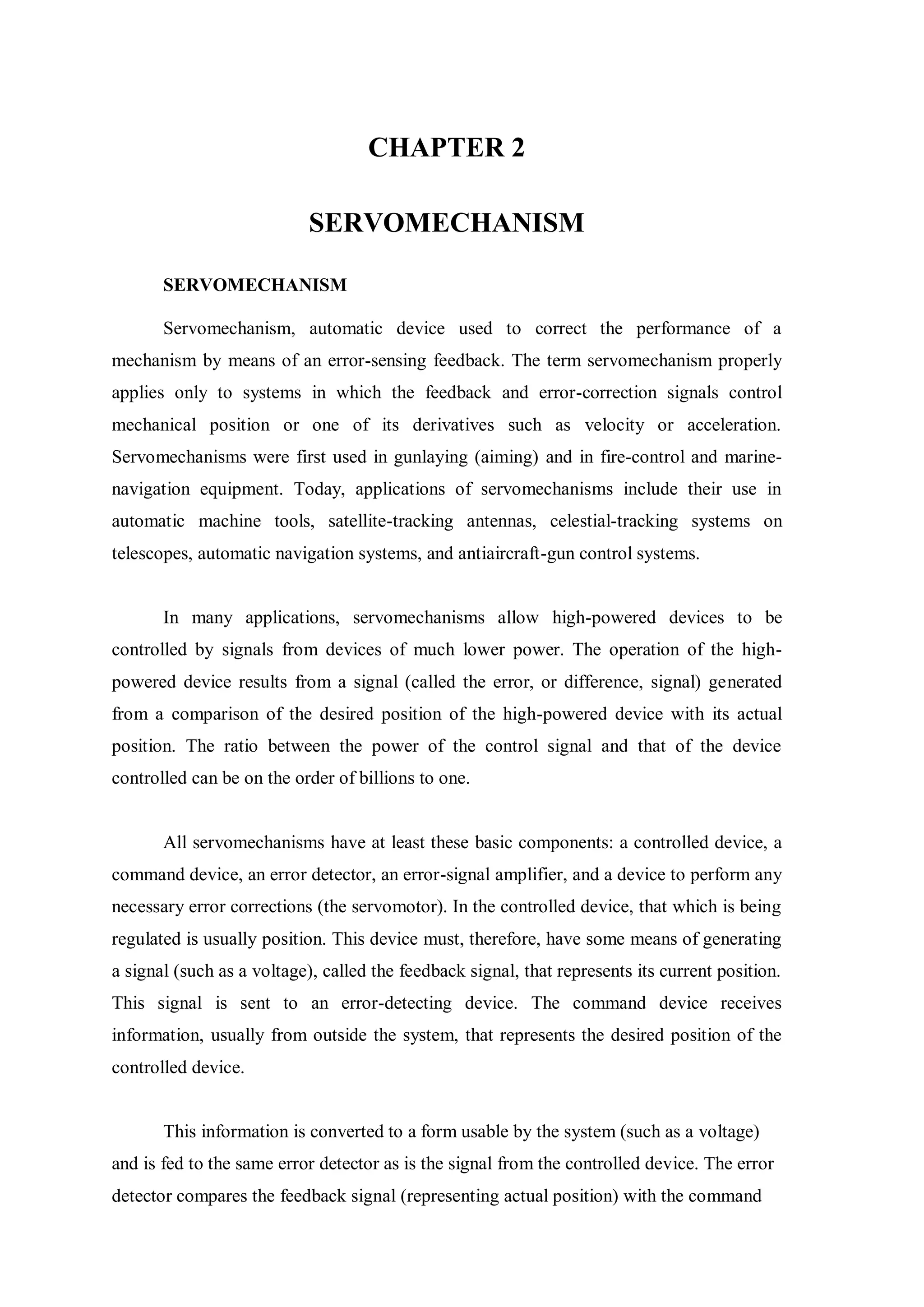
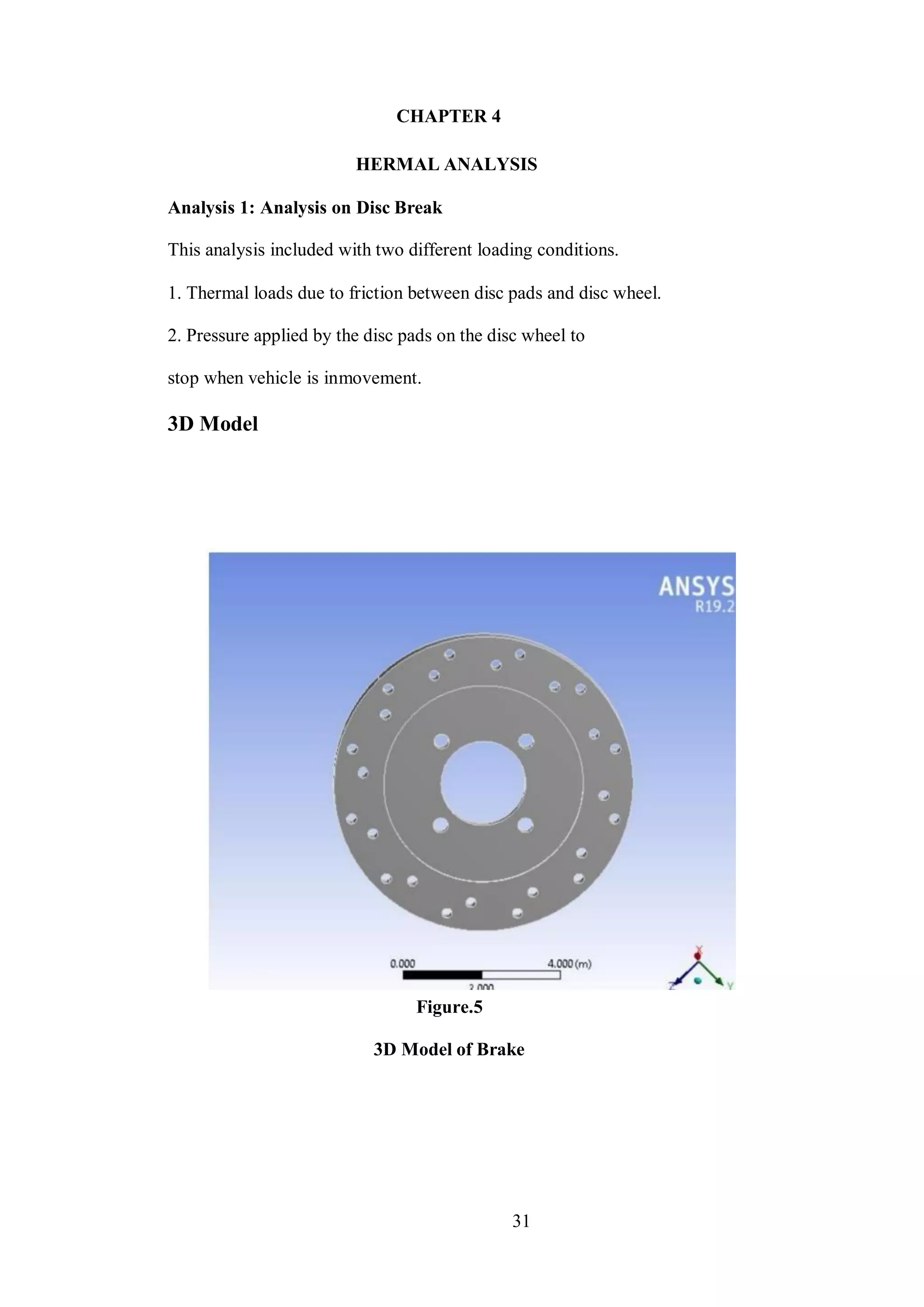
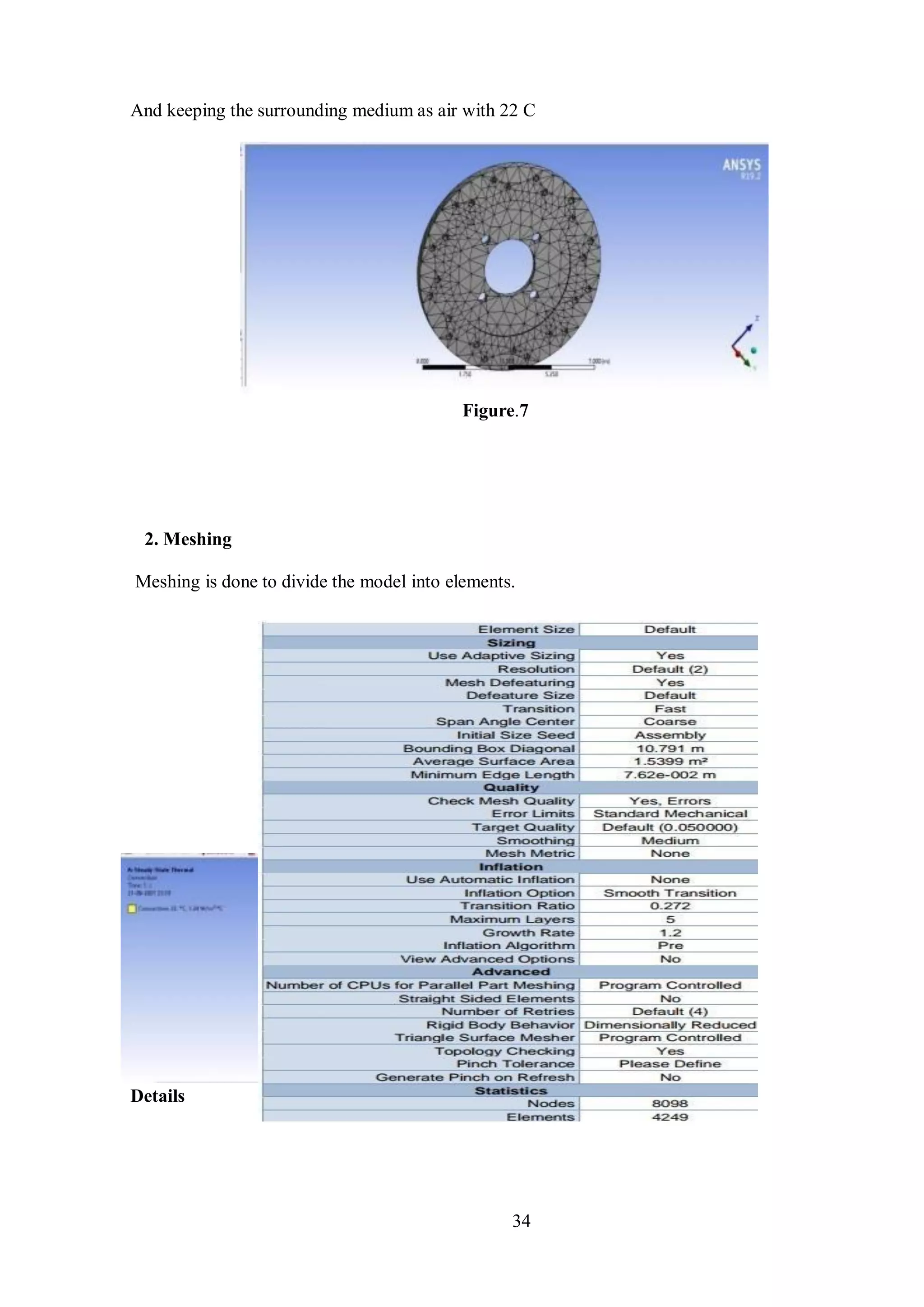
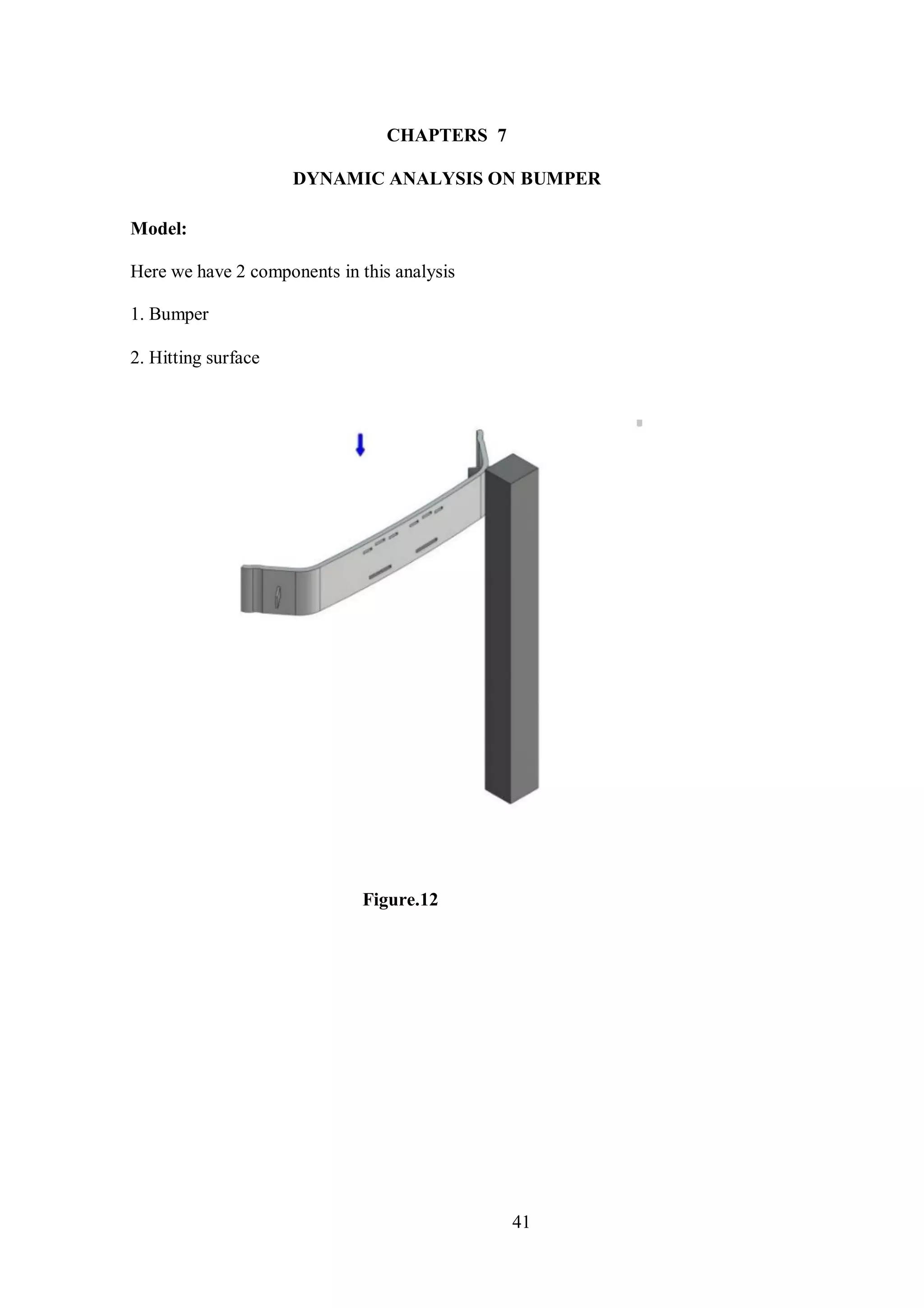
CHAPTER 5
STATICS ANALYSIS
Applying static load i.e., pressure due to brake pads on disc
Boundary conditions:
Applying rotational velocity of 100 rad/sec
Its because the vehicle will be in motion while applying the break.](https://image.slidesharecdn.com/finaldocumentabsautosaved-221111144841-fa7034b2/75/FINAL-DOCUMENT-Abs-Autosaved-pdf-37-2048.jpg)

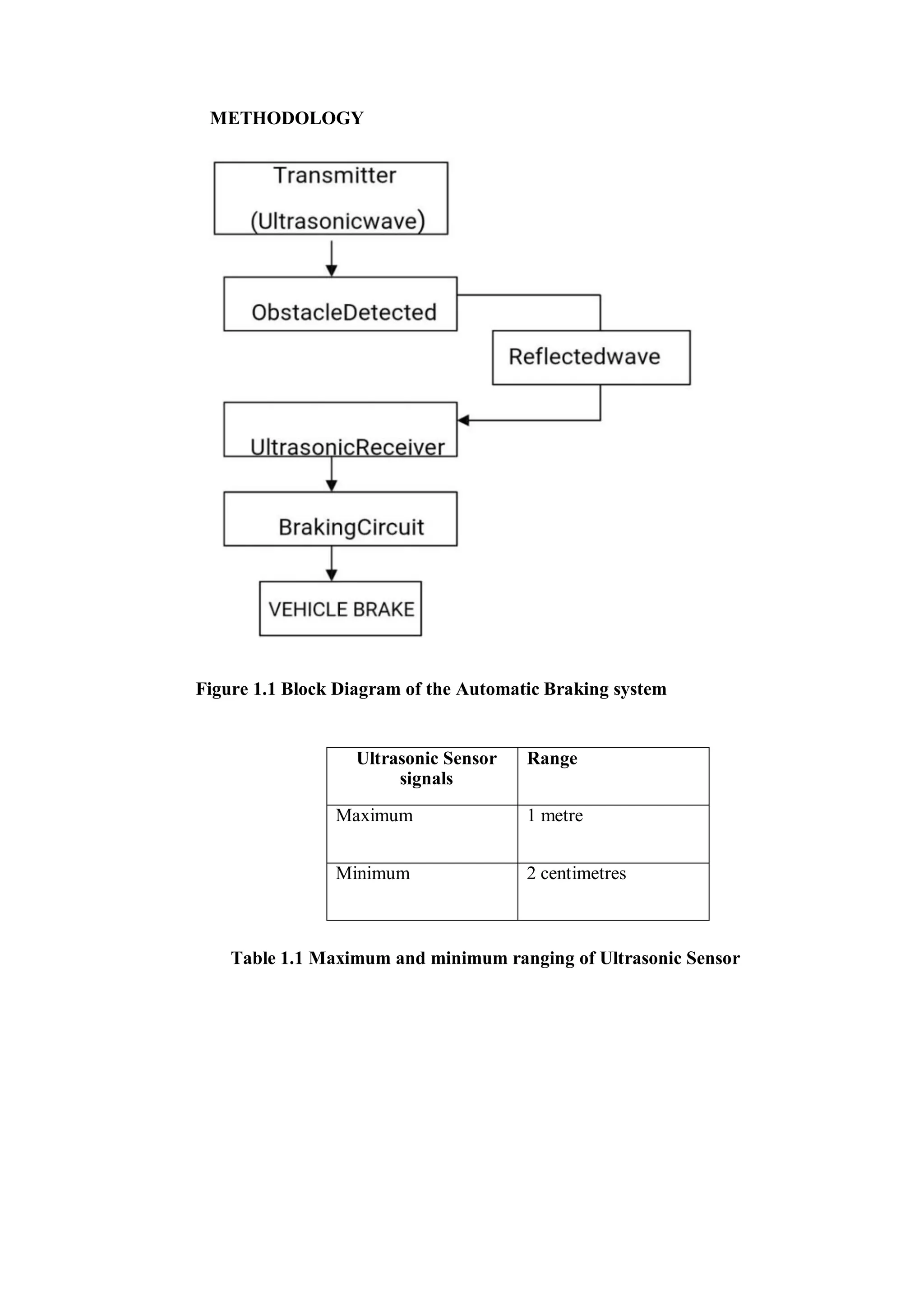
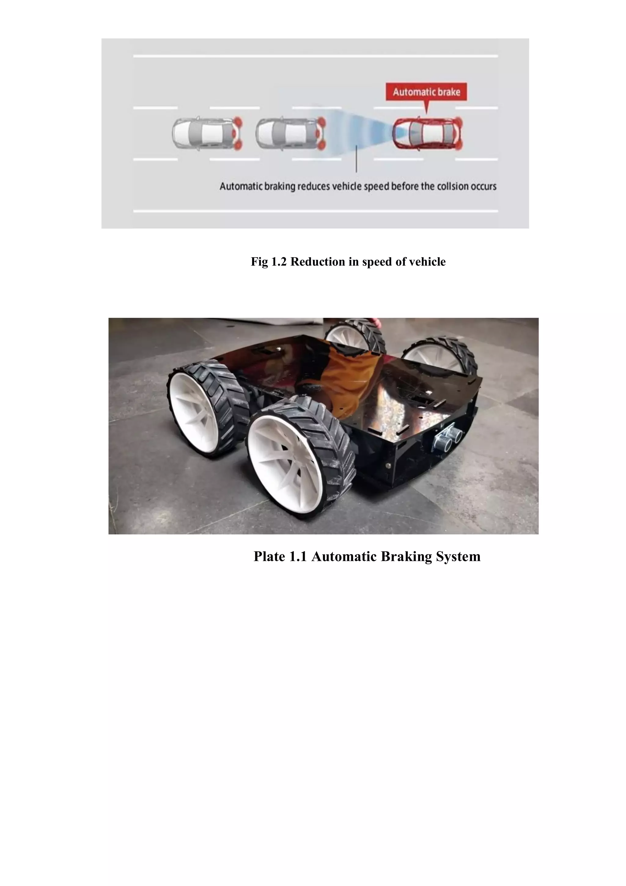
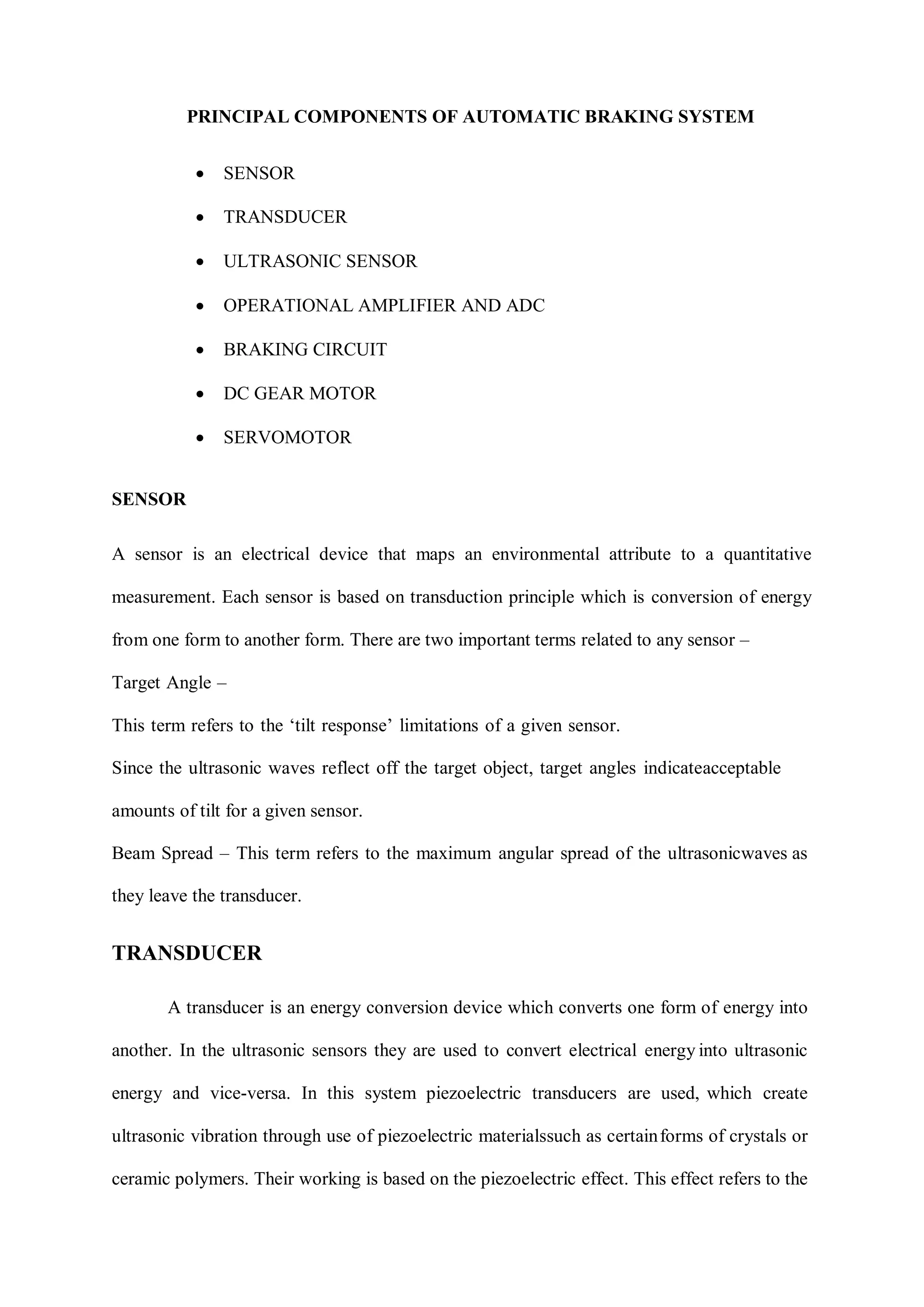
This document describes an automatic braking system for vehicles using ultrasonic sensors. It consists of an ultrasonic transmitter that emits ultrasonic waves and a receiver that receives reflected waves. An Arduino board processes the received signals and controls a DC gear motor and servomotor. The servomotor is connected to the braking mechanism and applies the brakes if an obstacle is detected within a certain distance from the vehicle. The system is designed to automatically brake the vehicle if the driver is unable to, in order to prevent accidents. Key components include ultrasonic sensors, an Arduino microcontroller, DC motor, servomotor and braking circuitry.