The paper discusses the development of a gesture-controlled chair that allows users to navigate a robotic chair using hand movements detected by an accelerometer. The system employs a microcontroller to process gesture signals and an RF module for communication, enabling motion in four directions: forward, backward, left, and right. This technology aims to assist the elderly and disabled, highlighting the potential for gesture-based interfaces in improving quality of life.
![The International Journal Of Engineering And Science (IJES)
|| Volume || 5 || Issue || 5 || Pages || PP -69-73 || 2016 ||
ISSN (e): 2319 – 1813 ISSN (p): 2319 – 1805
www.theijes.com The IJES Page 69
Gesture Controlled Chair
1
Yash Srivastava, 2
Anup Kumar Singh, 3
Shivangi Soni, 4
Sumedha Rai,
5
Samishtha Srivastava, 6
Vineet Saran
1,2,3,4,5,6
Department of Electronics & Communication Engineering, United College of Engineering &
Management, Naini, Allahabad
----------------------------------------------------------ABSTRACT-----------------------------------------------------------
Today human-machine interaction is moving away from mouse and pen and is becoming pervasive and much
more compatible with the physical world. With each passing day the gap between machines and humans is
being reduced with the introduction of new technologies to ease the standard of living. In this paper, a rigorous
analysis of different techniques of “Human-Machine Interaction” using gestures has been presented using
accelerometer. Gestures can originate from any bodily motion or state but commonly originate from
the face or hand. Robotics is the branch of engineering that deals with the design, construction, operation, and
application of robots, as well as computer systems for their control, sensory feedback, and information
processing we have implemented a system through which the user can give commands to a wireless robot using
gestures. Through this method, the user can control or navigate the robot by using gestures of his/her palm,
thereby interacting with the robotic system. The command signals are generated from these gestures using
accelerometer sensing [1]. These signals are then passed to the robot to navigate it in the specified directions.
Keywords : Accelerometer, ATMEGA 8 (Microcontroller), Gesture Recognition, L293D (Motor Driver IC),
RF Module.
-------------------------------------------------------------------------------------------------------------------------------------
Date of Submission: 20 April 2016 Date of Accepted: 13 May 2016
-------------------------------------------------------------------------------------------------------------------------------------------------------
I. INTRODUCTION
Recently, strong efforts have been carried out to develop intelligent and natural interfaces between users and
computer based systems based on human gestures. Gestures provide an intuitive interface to both human and
computer. A robot is usually an electro-mechanical machine that can perform tasks automatically. Some robots
require some degree of guidance, which may be done using a remote control or with a computer interface. A
gesture is an action that has to be seen by someone else and has to convey some piece of information. Gesture is
usually considered as a movement of part of the body, especially a hand or the head, to express an idea or
meaning.
Gesture recognition technologies are much younger in the world of today. At this time there is much active
research in this field and little in the way of publicly available implementations. Several approaches have been
developed for sensing gestures and controlling robots. Glove based technique is a well-known means of
recognizing hand gestures [2]. It utilizes a sensor attached to a glove that directly measures hand movements.
A Gesture Controlled Chair (robot) is a kind of robot which can be controlled by hand gestures and not the
old fashioned way by using buttons. The user just needs to wear a small transmitting device on his hand which
includes a sensor which is an accelerometer in our case. Movement of the hand in a specific direction will
transmit a command to the robot which will then move in a specific direction.
The transmitting device includes a Microcontroller (ATMEGA8) for assigning proper levels to the input
voltages from the accelerometer and an Encoder IC (HT12E) which is used to encode the four bit data and then
it will be transmitted by an RF Transmitter module.
At the receiving end an RF Receiver module will receive the encoded data and decode it by using a Decoder
IC (HT12D). This data is then processed and passed onto a motor driver IC (L293D) to rotate the motors in a
special configuration to make the chair (robot) move in the same direction as that of the hand gestures i.e.
forward, backward, left and right.
In this paper, a gesture based system (using Accelerometer- ADXL335) has been incorporated to control the
robot by using 3-axis accelerometers. The prime aim of the design is that the chair (robot) starts the movement as
soon as the operator makes a gesture or posture or any motion. The Robot is synchronized with the gestures
(hand postures) of the operator.](https://image.slidesharecdn.com/l0505069073-160908091437/85/Gesture-Controlled-Chair-1-320.jpg)
![The International Journal Of Engineering And Science (IJES)
|| Volume || 5 || Issue || 5 || Pages || PP -69-73 || 2016 ||
ISSN (e): 2319 – 1813 ISSN (p): 2319 – 1805
www.theijes.com The IJES Page 69
Gesture Controlled Chair
1
Yash Srivastava, 2
Anup Kumar Singh, 3
Shivangi Soni, 4
Sumedha Rai,
5
Samishtha Srivastava, 6
Vineet Saran
1,2,3,4,5,6
Department of Electronics & Communication Engineering, United College of Engineering &
Management, Naini, Allahabad
----------------------------------------------------------ABSTRACT-----------------------------------------------------------
Today human-machine interaction is moving away from mouse and pen and is becoming pervasive and much
more compatible with the physical world. With each passing day the gap between machines and humans is
being reduced with the introduction of new technologies to ease the standard of living. In this paper, a rigorous
analysis of different techniques of “Human-Machine Interaction” using gestures has been presented using
accelerometer. Gestures can originate from any bodily motion or state but commonly originate from
the face or hand. Robotics is the branch of engineering that deals with the design, construction, operation, and
application of robots, as well as computer systems for their control, sensory feedback, and information
processing we have implemented a system through which the user can give commands to a wireless robot using
gestures. Through this method, the user can control or navigate the robot by using gestures of his/her palm,
thereby interacting with the robotic system. The command signals are generated from these gestures using
accelerometer sensing [1]. These signals are then passed to the robot to navigate it in the specified directions.
Keywords : Accelerometer, ATMEGA 8 (Microcontroller), Gesture Recognition, L293D (Motor Driver IC),
RF Module.
-------------------------------------------------------------------------------------------------------------------------------------
Date of Submission: 20 April 2016 Date of Accepted: 13 May 2016
-------------------------------------------------------------------------------------------------------------------------------------------------------
I. INTRODUCTION
Recently, strong efforts have been carried out to develop intelligent and natural interfaces between users and
computer based systems based on human gestures. Gestures provide an intuitive interface to both human and
computer. A robot is usually an electro-mechanical machine that can perform tasks automatically. Some robots
require some degree of guidance, which may be done using a remote control or with a computer interface. A
gesture is an action that has to be seen by someone else and has to convey some piece of information. Gesture is
usually considered as a movement of part of the body, especially a hand or the head, to express an idea or
meaning.
Gesture recognition technologies are much younger in the world of today. At this time there is much active
research in this field and little in the way of publicly available implementations. Several approaches have been
developed for sensing gestures and controlling robots. Glove based technique is a well-known means of
recognizing hand gestures [2]. It utilizes a sensor attached to a glove that directly measures hand movements.
A Gesture Controlled Chair (robot) is a kind of robot which can be controlled by hand gestures and not the
old fashioned way by using buttons. The user just needs to wear a small transmitting device on his hand which
includes a sensor which is an accelerometer in our case. Movement of the hand in a specific direction will
transmit a command to the robot which will then move in a specific direction.
The transmitting device includes a Microcontroller (ATMEGA8) for assigning proper levels to the input
voltages from the accelerometer and an Encoder IC (HT12E) which is used to encode the four bit data and then
it will be transmitted by an RF Transmitter module.
At the receiving end an RF Receiver module will receive the encoded data and decode it by using a Decoder
IC (HT12D). This data is then processed and passed onto a motor driver IC (L293D) to rotate the motors in a
special configuration to make the chair (robot) move in the same direction as that of the hand gestures i.e.
forward, backward, left and right.
In this paper, a gesture based system (using Accelerometer- ADXL335) has been incorporated to control the
robot by using 3-axis accelerometers. The prime aim of the design is that the chair (robot) starts the movement as
soon as the operator makes a gesture or posture or any motion. The Robot is synchronized with the gestures
(hand postures) of the operator.](https://image.slidesharecdn.com/l0505069073-160908091437/75/Gesture-Controlled-Chair-1-2048.jpg)
![Gesture Controlled Chair
www.theijes.com The IJES Page 70
1.1 ANALYSIS
The objective of this project is to use the concept of gesture recognition to control a chair (robot). The primary
emphasis is laid on the mechanism of gesture recognition i.e. GR technology which is achieved by the help of
accelerometer and its proposed mechanism [3]. For gesture recognition the accelerometer data is calibrated and
filtered. The accelerometer can measure the magnitude and direction of gravity in addition to movement induced
acceleration. In order to calibrate the accelerometer, we rotate the device's sensitive axis with respect to gravity
and use the resultant signal as an absolute measurement. The four proposed movements that will be tried to
achieve are: Left, Right, Stop, Forward and Backward. The flowchart for the analysis has been shown in Fig.1.
Fig. (1): Flow Chart
II. TECHNICAL REQUIREMENTS
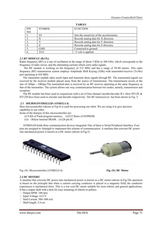
2.1 ACCELEROMETER (ADXL335)
An Accelerometer (Fig. 2) is an electromechanical device that measures acceleration forces. It can measure the
static acceleration of gravity in tilt-sensing applications, as well as dynamic acceleration resulting from motion,
shock, or vibration. It is a kind of sensor which record acceleration and gives an analog data while moving in X,
Y, Z direction or may be X, Y direction only depending on the type of the sensor ADXL 335 [3]. Some of its
features are as follows and also mentioned in table 1:
3-axis sensing.
10,000g shock survival.
Excellent temperature stability.
Fig. 2 Accelerometer Fig. 3 RF Transmitter Receiver](https://image.slidesharecdn.com/l0505069073-160908091437/85/Gesture-Controlled-Chair-2-320.jpg)
![Gesture Controlled Chair
www.theijes.com The IJES Page 72
III. WORKING ALGORITHM
The accelerometer records the hand movements in X & Y directions and outputs constant analog voltage levels.
These voltages are fed to the comparator of microcontroller which compares it with the reference voltages that
we have set via variable resistors attached to the IC. The resulting signal is encoded and then transmitted via RF
transmitter module.
The transmitted signal is received by the RF receiver, demodulated and then passed on to the Motor driver IC
for controlling the motion of wheels.
The working algorithms for the transmitter and receiver sides are given below in sections 3.1 and 3.2
respectively.
3.1 TRANSMITTER MODULE
a. RECEIVER MODULE
IV. IMPLEMENTATION
Gesture based chair is implemented as shown in Fig. 6 as per the details mentioned in the above sections. Chair
is moving in 4 directions forward, reverse, left and right with the help of gesture circuit which is mounted on
hand glove as shown in Fig. 7 and with the help of 4 gestures of hand moving in up, down, left and right
direction respectively.
V. FUTURE WORK
Technologies developed based on gesture [5] are now really affordable and converged with familiar and popular
technologies like TV, large screen. It’s ubiquitous and non-intrusive as we can install a camera or remote with
the TV. From this paper we can see the trends of gesture controlled communication systems. Easing of the
Technology use, affordability and familiarity indicate that gesture based user interface can open new opportunity
Fig. 6 Gesture Based Chair Fig. 7 Gesture Circuit Mounted on Hand Glove](https://image.slidesharecdn.com/l0505069073-160908091437/85/Gesture-Controlled-Chair-4-320.jpg)
![Gesture Controlled Chair
www.theijes.com The IJES Page 73
for elderly and disable people. The older population (65+) numbered 36.3 million, an increase of 3.1 million or
9.3% since 1994 and it’s growing over time. There will be more elderly people and fewer younger ones to care
for them. So we need to invest much more heavily in Assistive Living solutions. The research ‘A gesture
controlled communication aid for elderly and disabled people’ can be a significant task for future. The two
important aims of the research are to identify the different gestures of elderly and disabled people for
communication and to design a rich augmented-reality interface for communication via ubiquitous device [6].
VI. RESULT AND CONCLUSION
Enormous amount of work has been done on wireless gesture controlling of robots. In this paper, various
methodologies have been analyzed and reviewed with their merits and demerits under various operational and
functional strategies. Although recent researches in this field have made wireless gesture controlling a ubiquitous
phenomenon [6], it needs to acquire more focus in relevant areas of applications like home appliances,
wheelchairs, artificial nurses, table top screens etc. in a collaborative manner.
In this work Gesture Controlled Chair is built successfully as per planning which is moving in 4 directions
forward, reverse, left and right according to 4 gestures of hand. In this work the task is accomplished where
gesture controlled user interface for elderly and disable people has been reviewed along with the other gesture
technologies and a gesture based chair with better technology is built.
REFERENCES
[1] Sanna K., Juha K., Jani M. and Johan M (2006), Visualization of Hand Gestures for Pervasive Computing Environments, in the
Proceedings of the working conference on Advanced visual interfaces, ACM, Italy, p. 480-483.
[2] Wolf, C. G. Can people use gesture commands? IBM Research Report, (RC 11867), April 7, 1986.
[3] Juha K., Panu K., Jani M., Sanna K., Giuseppe S., Luca J. and Sergio D. M. Accelerometer-based gesture control for a design
environment, Springer, Finland, 2005.
[4] WII Nintendo , 2006, http://www.wii.com, Available at http://www.wii.com [Last accessed April 21, 2009].
[5] Malik, S. and Laszlo, J. (2004). Visual Touchpad: A Two-handed Gestural Input Device. In Proceedings of the ACM
International Conference on Multimodal Interfaces. p. 289
[6] Jani M., Juha K., Panu K., and Sanna K. (2004). Enabling fast and effortless customisation in accelerometer based gesture
interaction, in the Proceedings of the 3rd international conference on Mobile and ubiquitous multimedia. ACM, Finland. P. 25-
31](https://image.slidesharecdn.com/l0505069073-160908091437/85/Gesture-Controlled-Chair-5-320.jpg)