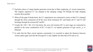
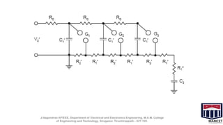
Version: MAMCET_VP-1.1
M.A.M. COLLEGE OF ENGINEERING AND TECHNOLOGY
Siruganur, Tiruchirappalli – 621 105.
06/11/2024
Year & Sem. : IV Year (EEE) – VII Semester
Faculty : Mr.J.Nagendran
Regulation : R2017
Course Code : EE8701
UNIT : III
COURSE NAME
EE8701-High Voltage Engineering
J.Nagendran, AP/EEE, Department of Electrical and Electronics
Engineering, M.A.M. College of Engineering and Technology,
Siruganur, Tiruchirappalli – 621 105.
06/11/2024
GENERAL OBJECTIVE
• To learn about the operation of Marx circuit
J.Nagendran AP/EEE, Department of Electrical and Electronics Engineering, M.A.M. College
of Engineering and Technology, Siruganur, Tiruchirappalli – 621 105.
06/11/2024
SPECIFIC OBJECTVES
Students will be able to
1. Explain the operation of Marx circuit
J.Nagendran AP/EEE, Department of Electrical and Electronics Engineering, M.A.M. College
of Engineering and Technology, Siruganur, Tiruchirappalli – 621 105.
06/11/2024
MARX CIRCUIT
J.Nagendran AP/EEE, Department of Electrical and Electronics Engineering, M.A.M. College
of Engineering and Technology, Siruganur, Tiruchirappalli – 621 105.
 Fig below shows a 3-stage impulse generator circuit due to Marx employing ‗b‘ circuit connections.
The impulse capacitors C1 are charged to the charging voltage V0 through the high charging
resistors Rcin parallel.
 When all the gaps G break down, the C1′ capacitances are connected in series so that C2 is charged
through the series connection of all the wave front resistances R1′ and finally all C1′ and C2 will
discharge through the resistors R2′ and R1′.
 Usually Rc>>R2 >>R1. If in Fig below the wave tail resistors R2′ in each stage are connected in
parallel to the series combination of R1′, G and C1′, an impulse generator of type circuit ‗a‘ is
obtained.
 In order that the Marx circuit operates consistently it is essential to adjust the distances between
various sphere gaps such that the first gap G1 is only slightly less than that of G2 and so on.
J.Nagendran AP/EEE, Department of Electrical and Electronics Engineering, M.A.M. College
of Engineering and Technology, Siruganur, Tiruchirappalli – 621 105.
J.Nagendran AP/EEE, Department of Electrical and Electronics Engineering, M.A.M. College
of Engineering and Technology, Siruganur, Tiruchirappalli – 621 105.
The wave front control resistance can have three possible locations
(i) entirely within the generator
(ii) entirely outside the generator
(iii)partly within and partly outside the generator.

HVE-UNIT-III T6 high voltage engineering.pptx

  • 1.
    Version: MAMCET_VP-1.1 M.A.M. COLLEGEOF ENGINEERING AND TECHNOLOGY Siruganur, Tiruchirappalli – 621 105. 06/11/2024 Year & Sem. : IV Year (EEE) – VII Semester Faculty : Mr.J.Nagendran Regulation : R2017 Course Code : EE8701 UNIT : III COURSE NAME EE8701-High Voltage Engineering J.Nagendran, AP/EEE, Department of Electrical and Electronics Engineering, M.A.M. College of Engineering and Technology, Siruganur, Tiruchirappalli – 621 105.
  • 2.
    06/11/2024 GENERAL OBJECTIVE • Tolearn about the operation of Marx circuit J.Nagendran AP/EEE, Department of Electrical and Electronics Engineering, M.A.M. College of Engineering and Technology, Siruganur, Tiruchirappalli – 621 105.
  • 3.
    06/11/2024 SPECIFIC OBJECTVES Students willbe able to 1. Explain the operation of Marx circuit J.Nagendran AP/EEE, Department of Electrical and Electronics Engineering, M.A.M. College of Engineering and Technology, Siruganur, Tiruchirappalli – 621 105.
  • 4.
    06/11/2024 MARX CIRCUIT J.Nagendran AP/EEE,Department of Electrical and Electronics Engineering, M.A.M. College of Engineering and Technology, Siruganur, Tiruchirappalli – 621 105.  Fig below shows a 3-stage impulse generator circuit due to Marx employing ‗b‘ circuit connections. The impulse capacitors C1 are charged to the charging voltage V0 through the high charging resistors Rcin parallel.  When all the gaps G break down, the C1′ capacitances are connected in series so that C2 is charged through the series connection of all the wave front resistances R1′ and finally all C1′ and C2 will discharge through the resistors R2′ and R1′.  Usually Rc>>R2 >>R1. If in Fig below the wave tail resistors R2′ in each stage are connected in parallel to the series combination of R1′, G and C1′, an impulse generator of type circuit ‗a‘ is obtained.  In order that the Marx circuit operates consistently it is essential to adjust the distances between various sphere gaps such that the first gap G1 is only slightly less than that of G2 and so on.
  • 5.
    J.Nagendran AP/EEE, Departmentof Electrical and Electronics Engineering, M.A.M. College of Engineering and Technology, Siruganur, Tiruchirappalli – 621 105.
  • 6.
    J.Nagendran AP/EEE, Departmentof Electrical and Electronics Engineering, M.A.M. College of Engineering and Technology, Siruganur, Tiruchirappalli – 621 105. The wave front control resistance can have three possible locations (i) entirely within the generator (ii) entirely outside the generator (iii)partly within and partly outside the generator.

Editor's Notes

  • #1 Notes for Teachers: The Synopsis presentation should contain 1. Real life applications 2. Overview of the subject 3. PO’s CO’s of the course 4. Individual Units overview 5. Lesson Plan 6. Flip Class topics “ Be professionally dressed and use a QUALITY PEN. Never hand an ordinary PEN as a Cosmetic Effect”