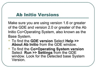
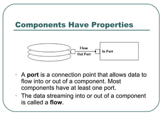
Session 2
Setting up
Ab Initio Versions
Make sure you are using version 1.6 or greater
of the GDE and version 2.0 or greater of the Ab
Initio Co>Operating System, also known as the
Base System.
 To find the GDE version Select Help >>
About Ab Initio from the GDE window.
 To find the Co>Operating System version
Select Run >> Settings from the GDE
window. Look for the Detected base System
Version.
Continue To Next Slide
More Details Visit
 More Details blog:http://sandyclassic.wordpress.com
 linkedin:https://www.linkedin.com/in/sandepsharma
 slideshare:http://www.slideshare.net/SandeepSharm
a65
 facebook:https://facebook.com/sandeepclassic
 google+ http://google.com/+SandeepSharmaa
 Twitter: https://twitter.com/sandeeclassic
 http://thedatawarehouseclassics.wordpress.com
 http://businessintelligencetechnologytrend.wordpress
.com
Components Have Properties
• A port is a connection point that allows data to
flow into or out of a component. Most
components have at least one port.
• The data streaming into or out of a component
is called a flow.
How to Create Flows
To Create a flow, follow these steps.
 Move your cursor over the Out Port of
the first component until the arrow and
Box symbols appear.
 Click and drag from the Out port of one
component to the In port of the next
component.
 Release the mouse button.
How to Delete Flows
 To delete a flow, highlight it (Click it )
then press the Delete key.
About Propagation
 When you connect flows in your graph,
most of the yellow highlighting
disappears because the GDE fills in
missing information for you,
automatically assigning component
layout and port properties. This behavior
is called PROPAGATION
 You can turn off propagation by choosing
Edit>> Propagation.
Are Your Flows Bent?
 Use the Straighten Flows button on the
Edit Toolbar to change the appearance
of the flows bent to aligned. Pull down:
 View > > Toolbars > > Edit Toolbar
 Bent flows
 Diagram to given
 Aligned flows
 Diagram to given
About the filter by expression
component
 The Filter by expression component
reads records from the In port, and
separates the records using the
expression in the select_expr
Parameter.
Tips about Runtime Status
 The GDE displays round colored indicators to
show the status of each component during
runtime.
About Viewing Data
 Ab Initio displays data in readable format
if the input is ASCII, EBCDIC, packed
decimal, binary, or another format.
 Ab Initio in many ways, releases you
from worrying about data type
information.
Deploying Graphs
 Now that you have a working application,
you no longer need the GDE to run it.
 If you choose Run > > Deploy from the
main menu, the GDE writes a script to
the control node that production staff can
run from a command line interface.
Ab Initio Files
 The Run Settings dialog specifies your host
directory. Your file structure for this tutorial
should look like this
 The top- level directory is tutorial; the
subdirectories are: answers, dat, dml and xfr.
DML Expressions
 Although the GDE mainly uses drag-and-
drop methodology, you can employ Ab
Initio’s Data Manipulation Language to
process your data.
Summary
 Component Organizer – Storage place for
components
 Components – the building blocks of Ab
Initio application. Dataset components are
the inputs and outputs. Program components
are the processing stages.
 Deploy – method for copying a graph to the
control node(sometimes called HOST) to run
it without the GDE. The generated shell script
and supporting files go to production.
Summary Cont’d
 DML – acronym for Ab Initio’s data
Manipulation Language.
 File Extentions – suffixes for your Ab
Initio files. Use Dat for data files, dml for
record format files, and xfr for transform
function files.
 Flows – streams of data between
components In your graph.
Summary Cont’d
 GDE Toolbars – Menus and buttons at the
top of the GDE workspace that let you
manipulate the Graphical Development
Environment including adding components
and running applications. The toolbars are
Main, Run, Phase, and Edit.
 Run Settings – method of configuring the
GDE to communicate with the control node.
The AbInitio Co>Operating system software
resides on the control node.
Summary Cont’d
 Graph – a diagram that defines the various
processing stages of a task and streams of data as
they move from one stage to another. Visually,
stages are represented by components, and streams
are represented by flows. The collection of
components and flows connected together embody
your Ab Initio graph.
 Ports – Connection points between components and
flows. Each component has at least one port(in or
out). Some ports must be connected to multiple
flows. We will talk multiple flows later. Every port has
a record format. Whenever possible, let record
formats propagate.
Summary Cont’d
 Run Settings – method of configuring the GDE to
communicate with the control node. The Ab Initio
Co>Operating System software resides on the
control node.
 Runtime Status – round colored indicators on your
graph that give you direct feedback about the
success or failure of your application. White is the
starting position, green represents an in-progress
state, blue stands for success, and red means error.
 Yellow Reminders – highlighted areas in your graph
that nudge you to supply missing information. These
are also called “To Do” cues.

Ab initio beginner's course topic 2

  • 1.
  • 2.
    Ab Initio Versions Makesure you are using version 1.6 or greater of the GDE and version 2.0 or greater of the Ab Initio Co>Operating System, also known as the Base System.  To find the GDE version Select Help >> About Ab Initio from the GDE window.  To find the Co>Operating System version Select Run >> Settings from the GDE window. Look for the Detected base System Version.
  • 3.
    Continue To NextSlide More Details Visit  More Details blog:http://sandyclassic.wordpress.com  linkedin:https://www.linkedin.com/in/sandepsharma  slideshare:http://www.slideshare.net/SandeepSharm a65  facebook:https://facebook.com/sandeepclassic  google+ http://google.com/+SandeepSharmaa  Twitter: https://twitter.com/sandeeclassic  http://thedatawarehouseclassics.wordpress.com  http://businessintelligencetechnologytrend.wordpress .com
  • 4.
    Components Have Properties •A port is a connection point that allows data to flow into or out of a component. Most components have at least one port. • The data streaming into or out of a component is called a flow.
  • 5.
    How to CreateFlows To Create a flow, follow these steps.  Move your cursor over the Out Port of the first component until the arrow and Box symbols appear.  Click and drag from the Out port of one component to the In port of the next component.  Release the mouse button.
  • 6.
    How to DeleteFlows  To delete a flow, highlight it (Click it ) then press the Delete key.
  • 7.
    About Propagation  Whenyou connect flows in your graph, most of the yellow highlighting disappears because the GDE fills in missing information for you, automatically assigning component layout and port properties. This behavior is called PROPAGATION  You can turn off propagation by choosing Edit>> Propagation.
  • 8.
    Are Your FlowsBent?  Use the Straighten Flows button on the Edit Toolbar to change the appearance of the flows bent to aligned. Pull down:  View > > Toolbars > > Edit Toolbar  Bent flows  Diagram to given  Aligned flows  Diagram to given
  • 9.
    About the filterby expression component  The Filter by expression component reads records from the In port, and separates the records using the expression in the select_expr Parameter.
  • 10.
    Tips about RuntimeStatus  The GDE displays round colored indicators to show the status of each component during runtime.
  • 11.
    About Viewing Data Ab Initio displays data in readable format if the input is ASCII, EBCDIC, packed decimal, binary, or another format.  Ab Initio in many ways, releases you from worrying about data type information.
  • 12.
    Deploying Graphs  Nowthat you have a working application, you no longer need the GDE to run it.  If you choose Run > > Deploy from the main menu, the GDE writes a script to the control node that production staff can run from a command line interface.
  • 13.
    Ab Initio Files The Run Settings dialog specifies your host directory. Your file structure for this tutorial should look like this  The top- level directory is tutorial; the subdirectories are: answers, dat, dml and xfr.
  • 14.
    DML Expressions  Althoughthe GDE mainly uses drag-and- drop methodology, you can employ Ab Initio’s Data Manipulation Language to process your data.
  • 15.
    Summary  Component Organizer– Storage place for components  Components – the building blocks of Ab Initio application. Dataset components are the inputs and outputs. Program components are the processing stages.  Deploy – method for copying a graph to the control node(sometimes called HOST) to run it without the GDE. The generated shell script and supporting files go to production.
  • 16.
    Summary Cont’d  DML– acronym for Ab Initio’s data Manipulation Language.  File Extentions – suffixes for your Ab Initio files. Use Dat for data files, dml for record format files, and xfr for transform function files.  Flows – streams of data between components In your graph.
  • 17.
    Summary Cont’d  GDEToolbars – Menus and buttons at the top of the GDE workspace that let you manipulate the Graphical Development Environment including adding components and running applications. The toolbars are Main, Run, Phase, and Edit.  Run Settings – method of configuring the GDE to communicate with the control node. The AbInitio Co>Operating system software resides on the control node.
  • 18.
    Summary Cont’d  Graph– a diagram that defines the various processing stages of a task and streams of data as they move from one stage to another. Visually, stages are represented by components, and streams are represented by flows. The collection of components and flows connected together embody your Ab Initio graph.  Ports – Connection points between components and flows. Each component has at least one port(in or out). Some ports must be connected to multiple flows. We will talk multiple flows later. Every port has a record format. Whenever possible, let record formats propagate.
  • 19.
    Summary Cont’d  RunSettings – method of configuring the GDE to communicate with the control node. The Ab Initio Co>Operating System software resides on the control node.  Runtime Status – round colored indicators on your graph that give you direct feedback about the success or failure of your application. White is the starting position, green represents an in-progress state, blue stands for success, and red means error.  Yellow Reminders – highlighted areas in your graph that nudge you to supply missing information. These are also called “To Do” cues.