A Review of Suspension using Magneto-rheological Fluid
•
0 likes•8 views

https://www.irjet.net/archives/V9/i4/IRJET-V9I4212.pdf

Recommended
Recommended
More Related Content
Similar to A Review of Suspension using Magneto-rheological Fluid
Similar to A Review of Suspension using Magneto-rheological Fluid (20)
More from IRJET Journal
More from IRJET Journal (20)
Recently uploaded
Recently uploaded (20)
A Review of Suspension using Magneto-rheological Fluid
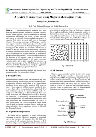
- 1. International Research Journal of Engineering and Technology (IRJET) e-ISSN: 2395-0056 Volume: 09 Issue: 04 | Apr 2022 www.irjet.net p-ISSN: 2395-0072 © 2022, IRJET | Impact Factor value: 7.529 | ISO 9001:2008 Certified Journal | Page 1219 A Review of Suspension using Magneto-rheological Fluid Vinay Patil1, Vineet Patil2 1,2 D. Y. Patil College of Engineering, Ambi, Maharashtra ---------------------------------------------------------------------***--------------------------------------------------------------------- Abstract - Magneto-rheological dampers are more generally referred to as MR dampers. MR damper is a smart damper, that's used as a vehicle suspension for vibration manipulation. MR fluids fall in a category of smart materials that react to an externally implemented electric powered or magnetic field with a dramatic difference in rheological behavior. The primary advantages of MR dampers are that they require very low magnitudes of power, have easy construction, quick reaction to the respective signal, and few moving parts. MR damper has acquired a terrific deal of interest in the last decade due to their being a potential technology to conduct semi-active control. It is consequently crucial to recognize the dynamic behavior of such devices whose nonlinear hysteresis is a rather complex phenomenon. The behavior of MR dampers may be represented with distinctive mathematical models. In this paper, a complete evaluation is then offered of the principles, characteristics, and engineering advantages of the MR fluid devices (specially dampers) studied in the last decade. Finally, the application potentialities of MR fluid gadgets are discussed Key Words: Magneto-rheological Fluid, MR Damper, Semi active controller, Electro-rheological fluid. 1. INTRODUCTION Magneto rheological (MR) fluids are substances that react toan implemented magnetic field with a dramatic difference in rheological behavior. An MR fluid is in a loose-flowing liquid state in the absence of a magnetic field, however, after a robust magnetic field its viscosity may be elevated by morethan orders of magnitude in a substantially brief time (milliseconds) and it reveals solid-like traits. The energy ofan MR fluid may be defined through shear yield stress. Moreover, the difference in viscosity is non-stop and reversible, i.e. after getting rid of the magnetic field the MRfluid can revert to a loose flowing liquid. Using those traits ofMR fluids, MR fluid elements have the capacity to offer simple, quiet, fast reactive interfaces among digital controls and mechanical systems. Hence, students and industrialistshave shown significant interest in MR fluids and their applications. 1.1 Magneto-rheological Fluid MR fluids fall into a category of smart fluids whose rheological properties (elasticity, plasticity, or viscosity) react to the presence of magnetic flux. MR fluids are suspensions of soft particles, having a diameter of 1–5 mm, in a unique service liquid that include water, mineral oil, artificial oil, and glycol. When a third-party magnetic flux is implemented in the fluid, the suspended particles of the fluid form chains and the suspension turns into like a semi-solid material because of the enhancement in the viscosity. Under the magnetic flux, an MR fluid behaves like a non- Newtonian fluid with controllable viscosity. Fig-1. MR Effect 1.2 MR Dampers These devices normally function in the valve mode. Typically, MR damper includes a hydraulic cylinder, magnetic coils, and MR fluid providing design simplicity. In addition to flux controllability and design simplicity, MR dampers have many different benefits which include they (i) require distinctly very low energy input, (ii) produce yield stress up to 100 kPa, (iii) may be stably operated in a extensive variety of temperature (−40–150 ◦C) and (iv) MR fluids aren't toxic and are insensitive to impurities. Fig-2. MR Damper
- 2. International Research Journal of Engineering and Technology (IRJET) e-ISSN: 2395-0056 Volume: 09 Issue: 04 | Apr 2022 www.irjet.net p-ISSN: 2395-0072 © 2022, IRJET | Impact Factor value: 7.529 | ISO 9001:2008 Certified Journal | Page 1220 Types of MR Dampers a) Mono tube b) Twin tube c) Double ended MR damper d) MR-Hydraulic hybrid damper. 2. LITERATURE REVIEW In Literature review, the authors had discussed the design, modeling, and types of MR Dampers and the suspension systems to provideridecomfort,road holdingcharacteristics, vehicle handling and road stability. Different types of MR damper models which can accurately predict the actual behavior of the real MR damper was also studied. Parameter optimization for the MR damper model was also studied and optimal parameters of the MR dampermodel werefound out. The authors used various types of controllers which gave better ride comfort to the passengers. Researchers took a quarter car model as it is one of the best and simplest ways for analysis of vehicle ride comfort with two degrees of freedom system and used the sinusoidal bump and random road profiles to analyze the performance of the vehicle. Experimental analysis of the MR damper was also done using HILS (Hardware in loop simulation). Andrzej Milecki , Miko" AjHauke, 2012,Application Of Magneto-rheological fluid In Industrial Shock Absorbers, discussed: Magnetorheological (MR) fluid,whichis capable of controlling the stopping process of moving objects, e.g. on transportation lines. The proposed solution makes it possible to adjust the braking force (by electronic controller) to the kinetic energy of the moving object. The paper presents an overview of passive shock absorbers. Next, the design concept of a semi- active shock absorber with the MR fluid is proposed. Theoretically the optimal breaking process occurs when the breaking force is constant on the whole stroke of the absorber. The passive shock absorbers that are in use now do not assure this. The braking pressure of those absorbers is not constant, and, as a result, the braking procedure is not optimal. Therefore, there is a requirement for improvement. Recently,semi-activedevices,also called ‘‘intelligent’’devices, were proposed for the damping of vibrations and oscillations. The parameters of these devices, just like the movement of opposite force, may be constantly modified with minimum power requirements. They make use of electrorheological (ER) or magnetorheological (MR)fluids. Such fluids may be pretty appealing for commercial applications in the stopping of moving elements on production lines. Compared to traditional electro rheological solutions, MR devices are morepotent and may be operated immediately from low- voltage energy supplies this is why MR fluids are much more frequently used. OBJECTIVES The suspension system is an integral part of an automobile which not only supports the vehicle body and separates the vehicle body from tires but also gives better ride comfort and safety to the passengers. Therefore, the objective of the project is a Performance Analysis of MR dampers for better ride comfort of the vehicle. 3. METHODOLOGY Methodology for making MR-Fluid CI particles (80% by wt) were mixed with oleic acid (0.25% by wt) for 30 minutes at 400 R.P.M in the stirrer. After that white grease (0.25% by wt) was poured and mixed for 30 minutes at 400 R.P.M in the same stirrer. Then servo medium e.g. paraffin oil(19.5% by wt) was poured in small amounts gradually (4% by wt) after every 30 minutes and mixed for 3 hrs at 450 R.P.M in the same stirrer. Fig-3 Making of MR Suspension • To replace the spring with MR fluid • To achieve high safety • It is an efficient system To generate magnetic flux density within MR fluid
- 3. International Research Journal of Engineering and Technology (IRJET) e-ISSN: 2395-0056 Volume: 09 Issue: 04 | Apr 2022 www.irjet.net p-ISSN: 2395-0072 © 2022, IRJET | Impact Factor value: 7.529 | ISO 9001:2008 Certified Journal | Page 1221 WORKING The working of MR fluid shock absorber is first you have to prepare the MR fluid because the standard fluid available in market is very expensive. The preparation of MR Fluid is given above. Now, this prepared MR fluid will be filled in cylinder, but normal Piston cylinder has no clearance even they have gas kit in between them hence here we are keeping 1 mm clearance so that all MR fluid will pass through this 1 mm clearance. In normal conditions, when the road is plain or good we require soft shock absorber therefore only 6 volt supply will be passed through Piston coil, which is an electromagnet because only 6 volts is required for MR fluid passing between Piston and cylinder is very less and we will get soft shock absorber. Now, suppose the vehicle is travelling off road, here the voltage supplied will be more and so will be the resistance offered by MR fluid due to high magnetic field developmen between Piston and cylinder resulting in a hard shock absorber. In this manner the stiffness of shock absorber can be changed. 3. CALCULATIONS DESIGN CALCULATIONS Area x Pressure = Force Output F = P X A Let us design the cylinder for 100 kg weight = 981 N 981 = P x π r2 P = 981/ π 242 P = 0.54 N/mm2. DESIGN OF CYLINDER Now for thickness of cylinder wall of cylinder, Hooks law We have, t = pd/2 σtensile where p = internal pressure= 0.54N/mm2 , & d = diameter of cylinder=48 mm selected, σtensile = permissible stress. Considering factor of safety as 4. We get permissible stress = ultimate stress/factor of safety σtensile = 135 N/mm2 Inputting this value in the thickness formula, We get, t = 0.54 x 48/2 x 135 = 25.92/270= 0.416 mm. t = 0.09 mm (say) but standard available cylinder in the market is 6 mm thick, so our design is safe. Outer Dia. of cylinder = 48 + (2 x 6) = 60 mm The minimum outside dia of cylinder is 60 mm Design of handle link W = maximum force applied = 981 N = 491 N (Since we are using 2 links) M = W x L M = 491 x 765/4 = 93903.75 N-mm And section modulus = Z = 1/6 bh2 Z = 1/6 x 5x252 Z = 1/6 x 3125 Z = 520.83 mm3. Now using the relation, Fb = M / Z Fb= 93903/ 520 = 180.29 N/mm2 Induced stress is less than allowable so design is safe Load of 100 kg on piston rod, so it may fail under bending M = WL/4 = 981 × 290/4 = 71122.5 N-mm Z= π( D 4 – d 4 ) /D x 32 Z= 167.55 mmᶟ σb (induced)= M/Z = 7122.5/167.5 = 424.5 N/mm² As induced bending stress is less then allowable bending stress i.e. 655 N/mm2 design is safe. 4. CONCLUSION MR fluids and MR fluid devices have substantially advanced in the last decade and there are a few industrial products were developed. This approach has been growing competitively in the major industrialized countries, particularly in the United States, Belarus, France, Germany, and Japan. The key to MR fluid technology is to put together high-overall performance MR fluids and to design MR fluid devices in structures. It may be seen that the MR fluid devices delivered in this seminar will continue to be the subject of significant studies and research in numerous fields as stated before. REFERENCES 1. S K Mangal and Ashwani Kumar, “Experimental and numerical studies of magneto-rheological (MR) damper” Chinese Journal of Engineering, vol. 2014, 7 pages, 2014, doi:10.1155/2014/915694, Hindawi Publishing Corporation 2. Ashwani, K, & Mangal, SK. (2012). Properties and applications of controllable fluids: A review. International Journal of Mechanical Engineering Research, 2(1), 57–66.Google Scholar
- 4. International Research Journal of Engineering and Technology (IRJET) e-ISSN: 2395-0056 Volume: 09 Issue: 04 | Apr 2022 www.irjet.net p-ISSN: 2395-0072 © 2022, IRJET | Impact Factor value: 7.529 | ISO 9001:2008 Certified Journal | Page 1222 3. Ashwani, K, & Mangal, SK. (2014). “Mathematical and experimental analysis of magneto rheological damper”. International Journal of Mechanic Systems Engg, 4(1), 11–15.Google Scholar 4. Carlson, JD, Catanzarite, DM, & St. Clair, KA. (1996). Commercial Magnetorheological Fluid Devices. International Journal of Modern Physics B, 10(23-24), 2857–2865.CrossRefGoogle Scholar 5. Chang-sheng, ZHU. (2003). A disc-type magneto- rheologic fluid damper. Journal of Zhejiang University science, 4(5), 514–519.CrossRefGoogle Scholar. 6. Designing with MR fluids. (1999) Lord Corporation Engineering Note, Thomas Lord Research Center, Cary, NC, USA. 7. Li, WH, & Guo, NQ. (2003). Finite element analysis and simulation evaluation of magnetorheological valve. Journal of Advanced Manufacturing Technology, 21, 438–445.CrossRefGoogle Scholar BIBLIOGRAPHY 1. Magnetorheological fluid devices: Principles, characteristics and applications in mechanical engineering, J Wang and G Meng State Key Laboratory of Vibration, Shock and Noise, Shanghai Jiao Tong University, People’s Republic of China and Siyuan Mechatronics Institute, Foshan University, Guangdong Province, People’s Republic of China. 2. M.J.L. Boada, J.A. Calvo, B.L. Boada, V. Díaz, Modelingof a magnetorheological damper by recursive lazy learning, International Journal of Non-Linear Mechanics, Volume 46, Issue 3, April 2011, Pages 479- 485, ISSN 0020- 7462,http://dx.doi.org/10.1016/j.ijnonlinmec.2008.1 1.019. 3. Nitin Ambhore, Shyamsundar Hivarale, Dr. D. R. Pangavhane, A Study of Bouc-Wen Model of Magnetorheological Fluid Damper for Vibration Control, International Journal of Engineering Research & Technology, Vol.2 - Issue 2 (February - 2013), ISSN: 2278-0181, http://www.ijert.org/view.php?id=2356&title=a- study-of-bouc-wen-model-of-magnetorheological- fluid- damper-for-vibration-control