Download to read offline

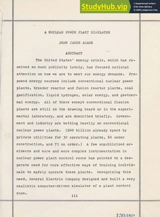
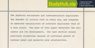
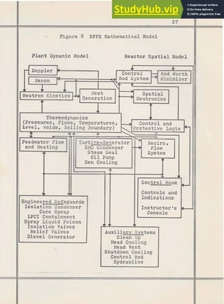
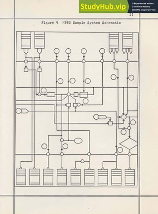

This document summarizes a 1973 master's thesis that describes the development of a nuclear power plant simulator. The simulator was developed by General Electric to provide realistic training for nuclear power plant operators. It physically duplicates the control room of the Dresden II nuclear power plant and uses a computer model to simulate the plant's dynamic responses to operator inputs, allowing operators to train as if operating the real plant without safety risks. The bulk of the thesis describes the simulator's development, including the mathematical and software models used to simulate the plant's behavior. It concludes by discussing some concerns about the continued growth of nuclear power, such as radioactive waste disposal and safety issues.


![Nonrenewable energy[1]](https://cdn.slidesharecdn.com/ss_thumbnails/nonrenewableenergy1-130513152957-phpapp02-thumbnail.jpg?width=640&height=640&fit=bounds)


