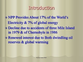
This document provides an overview of nuclear power plants, including:
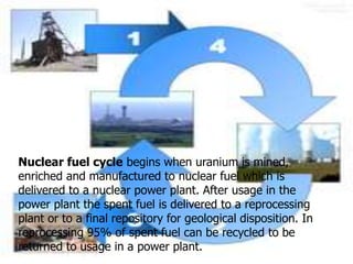
1) It discusses different reactor types used in nuclear power plants as well as the nuclear fuel cycle and life cycle of nuclear power.
2) It covers topics like solid nuclear waste, risks of accidents and attacks, and health and environmental impacts of nuclear power.
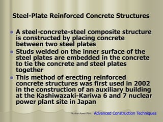
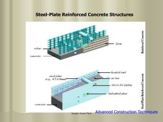
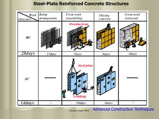
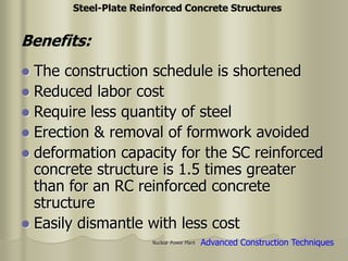
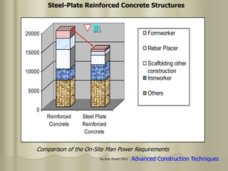
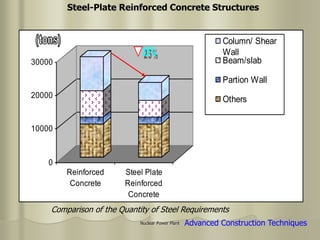
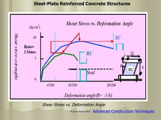
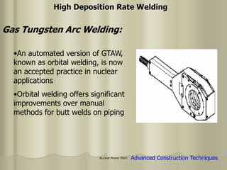
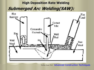
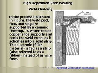
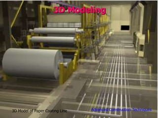
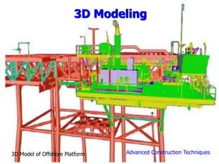
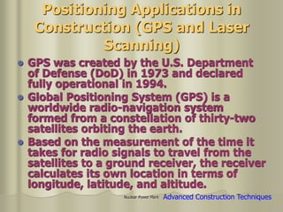
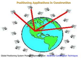
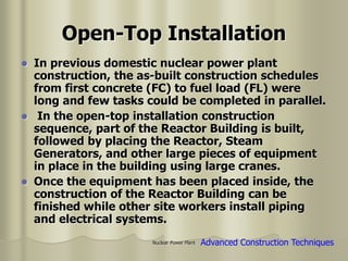
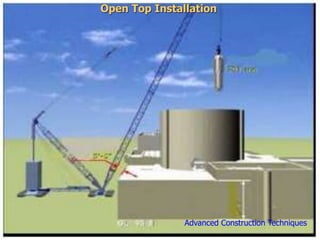
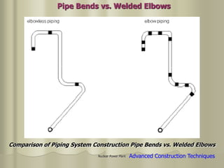
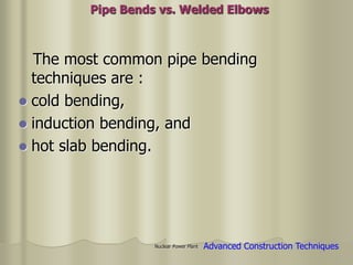
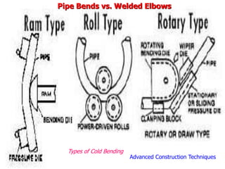
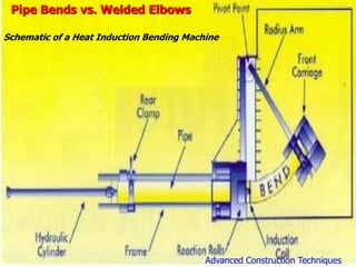
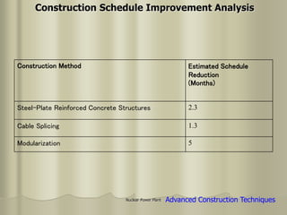
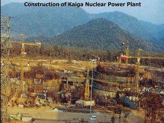
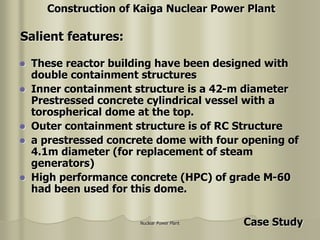
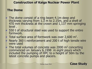
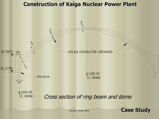
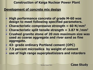
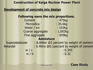
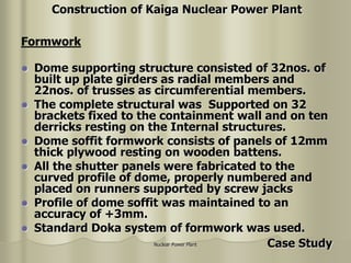
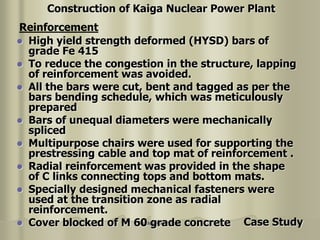
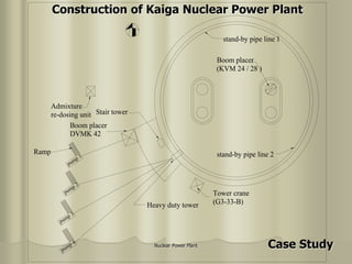
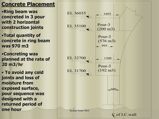
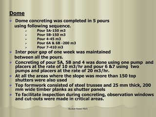
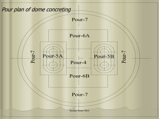
3) It also describes advanced construction techniques used for building nuclear power plants, such as steel-plate reinforced concrete structures and fiber-reinforced polymer rebar.