This document presents a new quadrilateral element (CQ4) formulated using the consecutive interpolation procedure (CIP) for finite element analysis. CIP enhances standard finite element approximations by including nodal gradients and higher-order polynomials. This allows the CQ4 element to have continuous nodal gradients, continuous stresses without smoothing, and avoid issues like volumetric locking. The CQ4 element is formulated and its accuracy and efficiency are demonstrated on benchmark problems, showing improvements over standard triangular and quadrilateral elements.
The document presents a study on using the NURBS-based isogeometric finite element method for free vibration and buckling analysis of laminated composite plates. Key points:
- An isogeometric finite element method is developed using NURBS basis functions for the approximation of deflection fields and geometry parameterization.
- The Lagrange multiplier method is used to enforce essential boundary conditions and an orthogonal transformation technique is applied to the discrete eigenvalue equation.
- Numerical examples are presented to demonstrate the accuracy of the proposed method for laminated composite plates with different boundary conditions, fiber orientations, and modes of vibration/buckling. Results are verified against analytical and other numerical solutions.
This document provides an overview of isogeometric analysis (IGA), which uses Non-Uniform Rational B-Splines (NURBS) as basis functions for both geometry representation and numerical analysis. The key benefits of IGA are a tighter integration between CAD and analysis models, reducing the time from design to analysis. Recent developments and applications of IGA in various fields are discussed, as well as some computational aspects and challenges. Alternative geometry representations such as T-splines are also introduced to address some limitations of NURBS.
Lecture on Introduction to finite element methods & its contentsMesayAlemuTolcha1
The document provides an overview of the Finite Element Method (FEM) course being taught. It discusses:
1. What FEM is and its common application areas like structural analysis, heat transfer, fluid flow.
2. The main steps in FEM including discretization, selecting interpolation functions, developing element matrices, assembling the global matrix, imposing boundary conditions, and solving equations.
3. Different element types like 1D, 2D, and 3D elements and the use of isoparametric formulations.
4. The history of FEM and how it has evolved from being used on mainframe computers to PCs.
Effectiveness of Element Free Galerkin Method over FEMIRJET Journal
This document compares the effectiveness of the element free Galerkin method (EFGM) to the finite element method (FEM) through analyzing the response of a cantilever beam under static loading conditions. EFGM is a meshfree numerical method that uses nodal shape functions rather than elements. The beam was modeled using EFGM in MATLAB and FEM in ANSYS, and the results were compared to the analytical solution. Both methods produced similar displacement results, with EFGM being slightly more accurate than FEM. EFGM is found to be superior to FEM for this problem due to its higher accuracy and ability to model complex geometries without mesh generation.
This document introduces the concept of isogeometric analysis, which uses basis functions generated from NURBS (Non-Uniform Rational B-Splines) to represent both geometry and solutions in computational analysis. The key advantages are maintaining exact geometry representation at all levels of refinement without needing to communicate with CAD software, and enabling various refinement strategies like h-, p-, and k-refinement in a simple way. Several examples are presented that demonstrate optimal convergence rates for problems in linear elasticity, shells, and advection-diffusion with internal/boundary layers. Isogeometric analysis is proposed as a viable alternative to standard finite element analysis that more tightly links geometry and analysis representations.
IRJET- Stress – Strain Field Analysis of Mild Steel Component using Finite El...IRJET Journal
This document analyzes the stress-strain field of a mild steel component under uniaxial loading using the finite element method. The component is modeled in MATLAB and Autodesk Fusion 360 using three elements and four nodes. Results are obtained for tensile forces of 1000N, 3000N, and 9000N. The displacement, stress, and strain values calculated in MATLAB are approximately similar to analytical solutions. Fusion 360 provides the maximum and minimum values within the component. The analysis demonstrates that finite element modeling can accurately determine stress-strain behavior under different loads.
This document presents a new methodology for optimal structural design that allows for changes in topology during the design process. The method formulates the problem as optimizing the distribution of material density in a reference domain, rather than varying boundaries. It uses a composite material with periodically distributed holes, and computes effective material properties using homogenization. This transforms the problem into a "sizing" optimization with density as the variable, avoiding remeshing issues of boundary variation methods while predicting optimal topology. Computational results demonstrate the method's ability to find designs with complex microstructures not achievable by boundary variation alone.
This article summarizes a new technique for efficiently analyzing variability in electromagnetic systems. The technique combines model order reduction and polynomial chaos expansion. It first uses model order reduction to generate a set of reduced order models from the original large system equations, evaluated over different points in the stochastic parameter space. It then computes the polynomial chaos expansion of the reduced order models to generate a final reduced order model that can accurately perform stochastic computations and variability analysis in an efficient manner. The technique avoids calculating the polynomial chaos expansion of the original large system matrices.
This article presents a novel technique that combines model order reduction and polynomial chaos expansion to efficiently perform variability analysis of electromagnetic systems. The key steps are:
1) Evaluate the original large system of equations at sample points in the stochastic space
2) Calculate a set of reduced order models with a common projection matrix
3) Compute the polynomial chaos expansion of the reduced order models
4) Calculate a polynomial chaos-based augmented system for variability analysis
The technique aims to overcome limitations of prior methods by first reducing the system and then applying polynomial chaos, rather than directly expanding the large original system.
This article summarizes a new technique for efficiently analyzing variability in electromagnetic systems. The technique combines model order reduction and polynomial chaos expansion. It first uses model order reduction to generate a set of reduced order models from the original large system equations, evaluated over different points in the stochastic parameter space. It then computes the polynomial chaos expansion of the reduced order models to generate a final reduced order model that can accurately perform stochastic computations and variability analysis in an efficient manner. The technique avoids calculating the polynomial chaos expansion of the original large system matrices.
This document describes a finite element method for modeling complex 3D crack propagation in quasi-brittle materials under static and dynamic loading conditions. The method embeds cohesive elements, which model potential cracks, between solid elements in regions of interest in the initial mesh. Neither remeshing nor predefined crack paths are required. The method was implemented in Abaqus and used to model crack propagation in four concrete structure examples, showing good agreement with experiments or other simulations. The method offers engineers an efficient tool for modeling 3D fracture problems using Abaqus' preprocessing, solving, and postprocessing capabilities.
This document describes a finite element method for modeling complex 3D crack propagation in quasi-brittle materials like concrete. The method embeds cohesive elements between solid elements in initial finite element meshes to model potential cracks. Neither remeshing nor predefined crack paths are required. The method was implemented in ABAQUS and used to model crack propagation in four concrete structure examples, showing good agreement with tests or other simulations. The method offers engineers an efficient tool for 3D fracture modeling using a commercial finite element package.
The document provides an introduction to the finite element method (FEM). It explains that FEM is a numerical method used to approximate solutions to partial differential equations. It works by dividing a complex problem into smaller, simpler parts called finite elements. This allows for the problem to be solved computationally. The document outlines the basic steps of FEM, including preprocessing (modeling, meshing), solving, and postprocessing (analyzing results). It also discusses applications, history, software, element types, meshing, convergence, and compatibility conditions of FEM.
The document discusses using a machine learning algorithm called Multi Expression Programming (MEP) to develop a computational model for predicting the compressive strength of carbon fiber-reinforced polymer (CFRP) confined concrete. The model will be based on an extensive database of 828 experimental specimens, incorporating parameters like specimen diameter, height, unconfined concrete strength, CFRP layer thickness, and elastic modulus. MEP is described as an advanced evolutionary algorithm that can accurately model problems with unspecified complexities better than other techniques. The validation and performance of the proposed MEP model will be assessed by comparing predictions to experimental data and other existing strength models.
Strengthening and customization of zinc facade panels using single point incr...Gert-Willem Van Gompel
Video compilation of some of the performed tests:
https://vimeo.com/171714619
Recently, architects and researchers on digital fabrication methods have been exploring the interaction between form, production process and material. This thesis investigates how the robotic single point incremental forming of sheet metal can make a useful contribution in transforming metal facade cassettes, by both focusing on its strengthening capacities and its ability to fabricate elements with a customized aesthetic. Through several brief studies, alternative process planning methods are explored and evaluated on their structural and architectural implications. Additionally the potential of reinforcing facade panels is investigated through simulation and tested during a depressurization test, simulating a wind load. This research shows how modifying the geometry of the cassettes enhances their structural performance. When achieving high degrees of accuracy is not the main concern, alternative process planning methods have shown to be promising for both decreasing the production time and increasing the rigidity of the formed part. The flexibility of such a robotic process enabled an explorative approach of manufacturing, resulting in an otherwise unachievable aesthetic. While considering the structural, aesthetic and economic aspects, this research aimed to set a general framework for further investigation, in order to ultimately introduce single point incrementally formed facade cassettes in common architectural practice.
A Density Control Based Adaptive Hexahedral Mesh Generation Algorithmijeei-iaes
This document summarizes an adaptive hexahedral mesh generation algorithm that uses density control. The algorithm involves 5 main steps: 1) Identifying the boundaries of the solid model, 2) Constructing refinement fields based on density metrics and generating an initial grid structure, 3) Generating a jagged core mesh by removing exterior elements, 4) Matching the core mesh surfaces to the solid model surfaces, 5) Improving mesh quality using optimization techniques. The algorithm aims to generate high quality hexahedral meshes with reasonably distributed density. It uses curvature and thickness criteria to refine the initial grid structure adaptively before generating the core mesh and performing surface matching and quality optimization.
A Comprehensive Introduction of the Finite Element Method for Undergraduate C...IJERA Editor
A simple and comprehensive introduction of the Finite Element Method for undergraduate courses is proposed. With very simple mathematics, students can easily understand it. The primary objective is to make students comfortable with the approach and cognizant of its potentials. The technique is based on the general overview of the steps involved in the solution of a typical finite element problem. This is followed by simple examples of mathematical developments which allow developing and demonstrating the major aspects of the finite element approach unencumbered by complicating factors.
International Journal of Engineering Research and Applications (IJERA) is an open access online peer reviewed international journal that publishes research and review articles in the fields of Computer Science, Neural Networks, Electrical Engineering, Software Engineering, Information Technology, Mechanical Engineering, Chemical Engineering, Plastic Engineering, Food Technology, Textile Engineering, Nano Technology & science, Power Electronics, Electronics & Communication Engineering, Computational mathematics, Image processing, Civil Engineering, Structural Engineering, Environmental Engineering, VLSI Testing & Low Power VLSI Design etc.
Applications of FEM in Geotechnical Engineering / State-of-the-ArtDr Mazin Alhamrany
This presentation supposed to be given during the 1st Iraqi International Conference on Geotechnical Engineering (ICGE) - Baghdad - 17-19 February 2020. I am uploading this document on LinkedIn as a contribution providing geotechnical engineers an insight for the earlier, recent and "potential" future applications of FEM in the field of Geotechnical Engineering. With my best wishes to the Iraqi Geotechnical Society.
This chapter discusses finite element analysis of a direct drive permanent magnet linear oscillating motor (PMLOM). It provides details of the motor construction and presents simulation results from FEMLAB6.2. The simulation analyzes the magnetic field distribution in the stator and mover using Maxwell's equations. It also shows magnetic flux plots and finite element meshes of the motor. Experimental results on force, input power, and voltage characteristics are presented and agree with simulation results, validating the motor model and analysis.
A short introduction presentation about the Basics of Finite Element Analysis. This presentation mainly represents the applications of FEA in the real time world.
This document describes an implementation of extended finite element method (X-FEM) in Abaqus for 3D fatigue crack growth and life prediction analysis. A level set representation is used to model evolving crack geometry without remeshing. Stress intensity factors are extracted on static and growing cracks to predict fatigue life using fracture mechanics criteria. Several examples are presented to validate the technique.
Modelling and simulation methodology for unidirectional composite laminates i...Olben Falcó Salcines
A reliable virtual testing framework for unidirectionally laminated composites is presented that allows the
prediction of failure loads and modes of general in-plane coupons with great realism. This is a toolset based on
finite element analysis that relies on a cohesive-frictional constitutive formulation coupled with the kinematics
of penalty-based contact surfaces, on sophisticated three-dimensional continuum damage models, and overall on
a modelling approach based on mesh structuring and crack-band erosion to capture the appropriate crack paths
in unidirectional fibre reinforced plies. An extensive and rigorous validation of the overall approach is presented,
demonstrating that the virtual testing laboratory is robust and can be reliably used in for composite materials
screening, design and certification.
An Algebraic Multigrid Solver For Transonic Flow ProblemsLisa Muthukumar
This document summarizes an article about developing an algebraic multigrid solver for transonic flow problems. The key points are:
- The solver is based on the full potential equation, which can model subsonic, transonic, and supersonic flows.
- Algebraic multigrid methods are used instead of geometric multigrid to avoid dependencies on grid geometry.
- The discretization approach handles the mixed elliptic-hyperbolic nature of the governing equations across flow regimes.
- Applications to complex geometries on structured grids are demonstrated, achieving an order of magnitude reduction in residual per cycle.
This document summarizes recent simulations of cold forming processes using the DEFORMTM-3D software. It describes three case studies: 1) the coining of a heat sink with self-contacting surfaces, 2) the assembly of a nut and plate with mesh-to-mesh contact, and 3) the extrusion of a helical gear using rotational symmetry. It also discusses simulations of thread rolling and stress analysis of the threading dies. The case studies demonstrate capabilities for modeling multiple deforming objects, self-contact, and large rotational problems. Finite element simulation has become an integral part of process design in metal forming industries.
This document describes finite element modeling techniques for simulating the thermal analysis of the electron beam melting (EBM) additive manufacturing process. It presents details on implementing both Abaqus user subroutines and a new Abaqus plugin called AM Modeler to model key phenomena in EBM, including a moving heat source, material state changes, and layer-by-layer deposition. Validation studies are performed and results from the user subroutines and AM Modeler are found to be in excellent agreement. A full 3D model is also developed to simulate the EBM printing of specific 3D objects. Source codes for the subroutines and AM Modeler implementation are made available to facilitate further research.
Introduction of finite element analysis1ssuser2209b4
The document provides an introduction to the finite element method (FEM). It discusses the different numerical, analytical, and experimental methods used to solve engineering problems. FEM involves discretizing a continuous domain into smaller, finite pieces called elements and using a mathematical representation to approximate the solution. It describes how FEM builds a stiffness matrix and assembles element equations to solve for unknown displacements. The document outlines the general FEM steps and highlights the merits and limitations of FEM, giving examples of its applications in stress analysis of industrial parts, fluid flow analysis, electromagnetic problems, and medical procedures.
How To Write A Self Evaluation Essay. Online assignment writing service.Brandi Gonzales
The document provides steps for requesting assignment writing help from HelpWriting.net:
1. Create an account and complete a request form providing instructions, sources, and deadline.
2. Writers will bid on the request and their qualifications can be reviewed to select a writer.
3. The writer will complete the assignment and customers can request revisions to ensure satisfaction. HelpWriting.net offers refunds for plagiarized work.
Thesis Format Sample Philippines - ProofreadwebBrandi Gonzales
This document provides instructions for requesting writing assistance from HelpWriting.net. It outlines a 5-step process: 1) Create an account with a password and email. 2) Complete a 10-minute order form providing instructions, sources, and deadline. 3) Review bids from writers and select one based on qualifications. 4) Review the completed paper and authorize payment or request revisions. 5) Request multiple revisions to ensure satisfaction, with the option of a full refund for plagiarized work. The document promotes HelpWriting.net's writing assistance and guarantees of original, high-quality content.
More Related Content
Similar to A Consecutive-Interpolation Quadrilateral Element (CQ4) Formulation And Applications
This article presents a novel technique that combines model order reduction and polynomial chaos expansion to efficiently perform variability analysis of electromagnetic systems. The key steps are:
1) Evaluate the original large system of equations at sample points in the stochastic space
2) Calculate a set of reduced order models with a common projection matrix
3) Compute the polynomial chaos expansion of the reduced order models
4) Calculate a polynomial chaos-based augmented system for variability analysis
The technique aims to overcome limitations of prior methods by first reducing the system and then applying polynomial chaos, rather than directly expanding the large original system.
This article summarizes a new technique for efficiently analyzing variability in electromagnetic systems. The technique combines model order reduction and polynomial chaos expansion. It first uses model order reduction to generate a set of reduced order models from the original large system equations, evaluated over different points in the stochastic parameter space. It then computes the polynomial chaos expansion of the reduced order models to generate a final reduced order model that can accurately perform stochastic computations and variability analysis in an efficient manner. The technique avoids calculating the polynomial chaos expansion of the original large system matrices.
This document describes a finite element method for modeling complex 3D crack propagation in quasi-brittle materials under static and dynamic loading conditions. The method embeds cohesive elements, which model potential cracks, between solid elements in regions of interest in the initial mesh. Neither remeshing nor predefined crack paths are required. The method was implemented in Abaqus and used to model crack propagation in four concrete structure examples, showing good agreement with experiments or other simulations. The method offers engineers an efficient tool for modeling 3D fracture problems using Abaqus' preprocessing, solving, and postprocessing capabilities.
This document describes a finite element method for modeling complex 3D crack propagation in quasi-brittle materials like concrete. The method embeds cohesive elements between solid elements in initial finite element meshes to model potential cracks. Neither remeshing nor predefined crack paths are required. The method was implemented in ABAQUS and used to model crack propagation in four concrete structure examples, showing good agreement with tests or other simulations. The method offers engineers an efficient tool for 3D fracture modeling using a commercial finite element package.
The document provides an introduction to the finite element method (FEM). It explains that FEM is a numerical method used to approximate solutions to partial differential equations. It works by dividing a complex problem into smaller, simpler parts called finite elements. This allows for the problem to be solved computationally. The document outlines the basic steps of FEM, including preprocessing (modeling, meshing), solving, and postprocessing (analyzing results). It also discusses applications, history, software, element types, meshing, convergence, and compatibility conditions of FEM.
The document discusses using a machine learning algorithm called Multi Expression Programming (MEP) to develop a computational model for predicting the compressive strength of carbon fiber-reinforced polymer (CFRP) confined concrete. The model will be based on an extensive database of 828 experimental specimens, incorporating parameters like specimen diameter, height, unconfined concrete strength, CFRP layer thickness, and elastic modulus. MEP is described as an advanced evolutionary algorithm that can accurately model problems with unspecified complexities better than other techniques. The validation and performance of the proposed MEP model will be assessed by comparing predictions to experimental data and other existing strength models.
Strengthening and customization of zinc facade panels using single point incr...Gert-Willem Van Gompel
Video compilation of some of the performed tests:
https://vimeo.com/171714619
Recently, architects and researchers on digital fabrication methods have been exploring the interaction between form, production process and material. This thesis investigates how the robotic single point incremental forming of sheet metal can make a useful contribution in transforming metal facade cassettes, by both focusing on its strengthening capacities and its ability to fabricate elements with a customized aesthetic. Through several brief studies, alternative process planning methods are explored and evaluated on their structural and architectural implications. Additionally the potential of reinforcing facade panels is investigated through simulation and tested during a depressurization test, simulating a wind load. This research shows how modifying the geometry of the cassettes enhances their structural performance. When achieving high degrees of accuracy is not the main concern, alternative process planning methods have shown to be promising for both decreasing the production time and increasing the rigidity of the formed part. The flexibility of such a robotic process enabled an explorative approach of manufacturing, resulting in an otherwise unachievable aesthetic. While considering the structural, aesthetic and economic aspects, this research aimed to set a general framework for further investigation, in order to ultimately introduce single point incrementally formed facade cassettes in common architectural practice.
A Density Control Based Adaptive Hexahedral Mesh Generation Algorithmijeei-iaes
This document summarizes an adaptive hexahedral mesh generation algorithm that uses density control. The algorithm involves 5 main steps: 1) Identifying the boundaries of the solid model, 2) Constructing refinement fields based on density metrics and generating an initial grid structure, 3) Generating a jagged core mesh by removing exterior elements, 4) Matching the core mesh surfaces to the solid model surfaces, 5) Improving mesh quality using optimization techniques. The algorithm aims to generate high quality hexahedral meshes with reasonably distributed density. It uses curvature and thickness criteria to refine the initial grid structure adaptively before generating the core mesh and performing surface matching and quality optimization.
A Comprehensive Introduction of the Finite Element Method for Undergraduate C...IJERA Editor
A simple and comprehensive introduction of the Finite Element Method for undergraduate courses is proposed. With very simple mathematics, students can easily understand it. The primary objective is to make students comfortable with the approach and cognizant of its potentials. The technique is based on the general overview of the steps involved in the solution of a typical finite element problem. This is followed by simple examples of mathematical developments which allow developing and demonstrating the major aspects of the finite element approach unencumbered by complicating factors.
International Journal of Engineering Research and Applications (IJERA) is an open access online peer reviewed international journal that publishes research and review articles in the fields of Computer Science, Neural Networks, Electrical Engineering, Software Engineering, Information Technology, Mechanical Engineering, Chemical Engineering, Plastic Engineering, Food Technology, Textile Engineering, Nano Technology & science, Power Electronics, Electronics & Communication Engineering, Computational mathematics, Image processing, Civil Engineering, Structural Engineering, Environmental Engineering, VLSI Testing & Low Power VLSI Design etc.
Applications of FEM in Geotechnical Engineering / State-of-the-ArtDr Mazin Alhamrany
This presentation supposed to be given during the 1st Iraqi International Conference on Geotechnical Engineering (ICGE) - Baghdad - 17-19 February 2020. I am uploading this document on LinkedIn as a contribution providing geotechnical engineers an insight for the earlier, recent and "potential" future applications of FEM in the field of Geotechnical Engineering. With my best wishes to the Iraqi Geotechnical Society.
This chapter discusses finite element analysis of a direct drive permanent magnet linear oscillating motor (PMLOM). It provides details of the motor construction and presents simulation results from FEMLAB6.2. The simulation analyzes the magnetic field distribution in the stator and mover using Maxwell's equations. It also shows magnetic flux plots and finite element meshes of the motor. Experimental results on force, input power, and voltage characteristics are presented and agree with simulation results, validating the motor model and analysis.
A short introduction presentation about the Basics of Finite Element Analysis. This presentation mainly represents the applications of FEA in the real time world.
This document describes an implementation of extended finite element method (X-FEM) in Abaqus for 3D fatigue crack growth and life prediction analysis. A level set representation is used to model evolving crack geometry without remeshing. Stress intensity factors are extracted on static and growing cracks to predict fatigue life using fracture mechanics criteria. Several examples are presented to validate the technique.
Modelling and simulation methodology for unidirectional composite laminates i...Olben Falcó Salcines
A reliable virtual testing framework for unidirectionally laminated composites is presented that allows the
prediction of failure loads and modes of general in-plane coupons with great realism. This is a toolset based on
finite element analysis that relies on a cohesive-frictional constitutive formulation coupled with the kinematics
of penalty-based contact surfaces, on sophisticated three-dimensional continuum damage models, and overall on
a modelling approach based on mesh structuring and crack-band erosion to capture the appropriate crack paths
in unidirectional fibre reinforced plies. An extensive and rigorous validation of the overall approach is presented,
demonstrating that the virtual testing laboratory is robust and can be reliably used in for composite materials
screening, design and certification.
An Algebraic Multigrid Solver For Transonic Flow ProblemsLisa Muthukumar
This document summarizes an article about developing an algebraic multigrid solver for transonic flow problems. The key points are:
- The solver is based on the full potential equation, which can model subsonic, transonic, and supersonic flows.
- Algebraic multigrid methods are used instead of geometric multigrid to avoid dependencies on grid geometry.
- The discretization approach handles the mixed elliptic-hyperbolic nature of the governing equations across flow regimes.
- Applications to complex geometries on structured grids are demonstrated, achieving an order of magnitude reduction in residual per cycle.
This document summarizes recent simulations of cold forming processes using the DEFORMTM-3D software. It describes three case studies: 1) the coining of a heat sink with self-contacting surfaces, 2) the assembly of a nut and plate with mesh-to-mesh contact, and 3) the extrusion of a helical gear using rotational symmetry. It also discusses simulations of thread rolling and stress analysis of the threading dies. The case studies demonstrate capabilities for modeling multiple deforming objects, self-contact, and large rotational problems. Finite element simulation has become an integral part of process design in metal forming industries.
This document describes finite element modeling techniques for simulating the thermal analysis of the electron beam melting (EBM) additive manufacturing process. It presents details on implementing both Abaqus user subroutines and a new Abaqus plugin called AM Modeler to model key phenomena in EBM, including a moving heat source, material state changes, and layer-by-layer deposition. Validation studies are performed and results from the user subroutines and AM Modeler are found to be in excellent agreement. A full 3D model is also developed to simulate the EBM printing of specific 3D objects. Source codes for the subroutines and AM Modeler implementation are made available to facilitate further research.
Introduction of finite element analysis1ssuser2209b4
The document provides an introduction to the finite element method (FEM). It discusses the different numerical, analytical, and experimental methods used to solve engineering problems. FEM involves discretizing a continuous domain into smaller, finite pieces called elements and using a mathematical representation to approximate the solution. It describes how FEM builds a stiffness matrix and assembles element equations to solve for unknown displacements. The document outlines the general FEM steps and highlights the merits and limitations of FEM, giving examples of its applications in stress analysis of industrial parts, fluid flow analysis, electromagnetic problems, and medical procedures.
Similar to A Consecutive-Interpolation Quadrilateral Element (CQ4) Formulation And Applications (20)
How To Write A Self Evaluation Essay. Online assignment writing service.Brandi Gonzales
The document provides steps for requesting assignment writing help from HelpWriting.net:
1. Create an account and complete a request form providing instructions, sources, and deadline.
2. Writers will bid on the request and their qualifications can be reviewed to select a writer.
3. The writer will complete the assignment and customers can request revisions to ensure satisfaction. HelpWriting.net offers refunds for plagiarized work.
Thesis Format Sample Philippines - ProofreadwebBrandi Gonzales
This document provides instructions for requesting writing assistance from HelpWriting.net. It outlines a 5-step process: 1) Create an account with a password and email. 2) Complete a 10-minute order form providing instructions, sources, and deadline. 3) Review bids from writers and select one based on qualifications. 4) Review the completed paper and authorize payment or request revisions. 5) Request multiple revisions to ensure satisfaction, with the option of a full refund for plagiarized work. The document promotes HelpWriting.net's writing assistance and guarantees of original, high-quality content.
Cartadalettera1 In 2021 Free Printable Stationery 3Brandi Gonzales
The document discusses the importance of establishing uplink over utilization protection thresholds in network infrastructure. It recommends setting thresholds based on percentage of usage compared to maximum available bandwidth, with enough margin of safety to alert when more bandwidth is needed. As a general rule, utilization percentages of 50-70% are acceptable for short periods, with 80% signaling that more bandwidth may be required and 90% indicating immediate action is needed. Establishing clear thresholds helps determine when additional network resources should be provisioned.
Diversity College Essay College Application EssayBrandi Gonzales
This document discusses a partnership between Velocity and Quetzal Inc., a point of sale system for independent shoe and dress boutiques. Some key details:
- Quetzal is a leading POS for independent shoe and clothing retailers in North America, with a focus on the complex needs of those industries.
- It offers comprehensive tools beyond just a POS, including multi-store management, advanced inventory control, customer management, and analytics.
- Quetzal values merchant feedback and works directly with customers to build a product tailored to their unique needs.
- Velocity has partnered with Quetzal to offer their POS system to its customers.
Mr. JBS Literature Class Proper Journal And Essay FormatBrandi Gonzales
The document discusses Susan Griffin's book "Our Story" and how it examines how rigid, top-down societies can cause problems like manufacturing obedient masses, loss of moral reasoning, and suppression of emotions. It provides the example of Heinrich Himmler's upbringing in early 20th century Germany, which had strong expectations of masculinity that Himmler did not fit, influencing his life and history. Griffin uses this complex story to show how expectations of normalcy in rigid cultures can undermine critical thinking.
1. Sigmund Freud developed the theory of psychoanalysis to understand the unconscious mind through techniques like dream analysis and free association.
2. Psychoanalysis posits that unconscious drives and desires influence conscious thoughts and behavior. By bringing the unconscious into awareness, repressed conflicts can be resolved.
3. Freud believed that psychoanalysis could provide relief from neurotic suffering and help patients achieve greater insight into themselves. It aimed to make the unconscious conscious.
The document provides instructions for using a writing service called HelpWriting.net. It outlines a 5-step process: 1) Create an account, 2) Complete an order form providing instructions and deadlines, 3) Review bids from writers and select one, 4) Review the completed paper and authorize payment, 5) Request revisions until satisfied. It emphasizes that original, high-quality content is guaranteed or a full refund will be provided.
Fresh English Writing An Objective News SummaryBrandi Gonzales
The document discusses the steps to request and complete an assignment writing request on the website HelpWriting.net. It outlines 5 steps: 1) Create an account with an email and password. 2) Complete a form with assignment details and deadline. 3) Review bids from writers and choose one. 4) Review the completed paper and authorize payment. 5) Request revisions to ensure satisfaction, and the company offers refunds for plagiarized work.
Five Ways To Repurpose Your. Online assignment writing service.Brandi Gonzales
The document provides a 5-step process for requesting and receiving writing assistance from HelpWriting.net. It explains that users must first create an account, then submit a request form with instructions and sources. Writers will bid on the request, and the user can select a writer and provide a deposit to start the work. Upon receiving a draft, the user can request revisions if needed. HelpWriting.net guarantees original, high-quality work and offers refunds for plagiarized content.
Breathtaking How To Write A Rese. Online assignment writing service.Brandi Gonzales
The document provides instructions for requesting writing assistance from HelpWriting.net. It outlines a 5-step process: 1) Create an account with a password and email. 2) Complete a 10-minute order form providing instructions, sources, and deadline. 3) Review bids from writers and select one based on qualifications. 4) Review the completed paper and authorize payment if satisfied. 5) Request revisions to ensure satisfaction, and HelpWriting.net offers refunds for plagiarized work.
Cute Lined Paper To Print And Download Other Lines TemplBrandi Gonzales
The document discusses how bacterial growth increases in space flight due to changes in their environment compared to Earth. Specifically, the lack of convection in microgravity restricts fluid movement around bacteria to just diffusion. This alters the extracellular fluid composition in a way that impacts bacterial growth rates and final cell densities. Studies aim to discover the inherent mechanisms driving increased bacterial growth during space flight by examining how metabolic waste products accumulate differently without fluid motion.
The document provides instructions for students seeking writing assistance from HelpWriting.net. There is a 5-step process:
1. Create an account with a password and email.
2. Complete a 10-minute order form providing instructions, sources, deadline, and attaching a sample if wanting the writer to mimic their style.
3. Review bids from writers for the request, choose one based on qualifications, order history, and feedback, then pay a deposit to start.
4. Review the completed paper and authorize final payment if pleased, or request free revisions.
5. Request multiple revisions to ensure satisfaction - HelpWriting.net promises original, high-quality work and refunds for plag
The Syrian civil war began in 2011 as popular demonstrations against President Bashar al-Assad and over four decades of Baath Party rule. The Syrian Army was deployed to quell the uprising, using military sieges against protesters. The conflict has since escalated into a full-scale civil war between forces loyal to Assad's government and opposition forces seeking to oust it. The war has received condemnation from the international community due to the government's violent response against protesters.
The document provides instructions for requesting writing assistance from HelpWriting.net. It outlines a 5-step process: 1) Create an account with a password and email. 2) Complete a form with assignment details. 3) Review bids from writers and select one. 4) Review the completed paper and authorize payment. 5) Request revisions until satisfied with the work. The service aims to match clients with qualified writers and stands by delivering original, high-quality content.
How To Overcome Anxiety And Fear Of Writing EssayBrandi Gonzales
Samuel L. Jackson is one of the most accomplished Hollywood actors. He grew up in Tennessee and was inspired to become an actor after watching movies as a child that depicted the struggles of Black people. Jackson joined a Black theatre company after college and began acting in off-Broadway productions. He met Morgan Freeman and Spike Lee, who helped launch his film career. Jackson has had a highly successful career spanning several decades, winning an Academy Award and Golden Globe. He is best known for his roles in Pulp Fiction, Avengers, and Django Unchained.
Top-Quality Paper Writing. Online assignment writing service.Brandi Gonzales
The document discusses the steps involved in getting top-quality paper writing assistance from the website HelpWriting.net, which includes creating an account, submitting a request form with instructions and deadline, reviewing writer bids and choosing one to complete the assignment, revising the paper if needed, and knowing that refunds are offered for plagiarized work. The process aims to match clients with qualified writers and ensure assignments are completed to a high standard through revisions and refund policies.
123 Best Anthropology Research Paper Topics ToBrandi Gonzales
President Abraham Lincoln led the United States for five years during a pivotal period of history, most notably guiding the country through the Civil War while emancipating slaves, yet his legacy extends beyond just these two momentous acts. As the 16th president, Lincoln navigated complex political and social challenges, working to preserve the Union and champion equal rights for all at a time of immense national division and turmoil. His resolute leadership during the Civil War era left an indelible mark on America and reshaped the country's future.
The short story collection explores the theme of entrapment and desire for freedom through the eyes of a young girl. As she grows up, she gains a greater understanding of the pain, turmoil, and injustice that exist in the world. Many characters feel physically or emotionally trapped, such as by the grandfather's cold and rigid personality embodied by the brick house he built. No one can truly survive or be happy while living under his oppressive rule, representing a desire among all people for freedom and escape from confinement.
Best College Essay Help Books. 10 Outstanding CoBrandi Gonzales
Here is a draft philosophy of nursing statement:
My philosophy of nursing is centered around compassionate, holistic care for all people. As a nurse, I believe in treating each patient with dignity and respect, regardless of their background or life circumstances.
Nursing is more than just treating physical ailments - it involves caring for the whole person. This means being attentive to patients' emotional, psychological and social needs in addition to their medical needs. I strive to see each patient as a unique individual with their own story, rather than just a diagnosis or condition.
Part of providing holistic care is empowering patients to be active participants in their own health. My role is to educate and support patients so they can make
003 Essay Abstract Example Page R. Online assignment writing service.Brandi Gonzales
The document provides instructions for creating an account and submitting assignment requests on the HelpWriting.net website. It outlines a 5-step process: 1) Create an account with an email and password. 2) Complete a form with assignment details, sources, and deadline. 3) Writers will bid on the request and the customer can choose a writer. 4) The customer will receive the paper and pay for it if satisfied. 5) Customers can request revisions to ensure satisfaction, and the company guarantees original content or a refund.
Philippine Edukasyong Pantahanan at Pangkabuhayan (EPP) CurriculumMJDuyan
(𝐓𝐋𝐄 𝟏𝟎𝟎) (𝐋𝐞𝐬𝐬𝐨𝐧 𝟏)-𝐏𝐫𝐞𝐥𝐢𝐦𝐬
𝐃𝐢𝐬𝐜𝐮𝐬𝐬 𝐭𝐡𝐞 𝐄𝐏𝐏 𝐂𝐮𝐫𝐫𝐢𝐜𝐮𝐥𝐮𝐦 𝐢𝐧 𝐭𝐡𝐞 𝐏𝐡𝐢𝐥𝐢𝐩𝐩𝐢𝐧𝐞𝐬:
- Understand the goals and objectives of the Edukasyong Pantahanan at Pangkabuhayan (EPP) curriculum, recognizing its importance in fostering practical life skills and values among students. Students will also be able to identify the key components and subjects covered, such as agriculture, home economics, industrial arts, and information and communication technology.
𝐄𝐱𝐩𝐥𝐚𝐢𝐧 𝐭𝐡𝐞 𝐍𝐚𝐭𝐮𝐫𝐞 𝐚𝐧𝐝 𝐒𝐜𝐨𝐩𝐞 𝐨𝐟 𝐚𝐧 𝐄𝐧𝐭𝐫𝐞𝐩𝐫𝐞𝐧𝐞𝐮𝐫:
-Define entrepreneurship, distinguishing it from general business activities by emphasizing its focus on innovation, risk-taking, and value creation. Students will describe the characteristics and traits of successful entrepreneurs, including their roles and responsibilities, and discuss the broader economic and social impacts of entrepreneurial activities on both local and global scales.
Chapter wise All Notes of First year Basic Civil Engineering.pptxDenish Jangid
Chapter wise All Notes of First year Basic Civil Engineering
Syllabus
Chapter-1
Introduction to objective, scope and outcome the subject
Chapter 2
Introduction: Scope and Specialization of Civil Engineering, Role of civil Engineer in Society, Impact of infrastructural development on economy of country.
Chapter 3
Surveying: Object Principles & Types of Surveying; Site Plans, Plans & Maps; Scales & Unit of different Measurements.
Linear Measurements: Instruments used. Linear Measurement by Tape, Ranging out Survey Lines and overcoming Obstructions; Measurements on sloping ground; Tape corrections, conventional symbols. Angular Measurements: Instruments used; Introduction to Compass Surveying, Bearings and Longitude & Latitude of a Line, Introduction to total station.
Levelling: Instrument used Object of levelling, Methods of levelling in brief, and Contour maps.
Chapter 4
Buildings: Selection of site for Buildings, Layout of Building Plan, Types of buildings, Plinth area, carpet area, floor space index, Introduction to building byelaws, concept of sun light & ventilation. Components of Buildings & their functions, Basic concept of R.C.C., Introduction to types of foundation
Chapter 5
Transportation: Introduction to Transportation Engineering; Traffic and Road Safety: Types and Characteristics of Various Modes of Transportation; Various Road Traffic Signs, Causes of Accidents and Road Safety Measures.
Chapter 6
Environmental Engineering: Environmental Pollution, Environmental Acts and Regulations, Functional Concepts of Ecology, Basics of Species, Biodiversity, Ecosystem, Hydrological Cycle; Chemical Cycles: Carbon, Nitrogen & Phosphorus; Energy Flow in Ecosystems.
Water Pollution: Water Quality standards, Introduction to Treatment & Disposal of Waste Water. Reuse and Saving of Water, Rain Water Harvesting. Solid Waste Management: Classification of Solid Waste, Collection, Transportation and Disposal of Solid. Recycling of Solid Waste: Energy Recovery, Sanitary Landfill, On-Site Sanitation. Air & Noise Pollution: Primary and Secondary air pollutants, Harmful effects of Air Pollution, Control of Air Pollution. . Noise Pollution Harmful Effects of noise pollution, control of noise pollution, Global warming & Climate Change, Ozone depletion, Greenhouse effect
Text Books:
1. Palancharmy, Basic Civil Engineering, McGraw Hill publishers.
2. Satheesh Gopi, Basic Civil Engineering, Pearson Publishers.
3. Ketki Rangwala Dalal, Essentials of Civil Engineering, Charotar Publishing House.
4. BCP, Surveying volume 1
Temple of Asclepius in Thrace. Excavation resultsKrassimira Luka
The temple and the sanctuary around were dedicated to Asklepios Zmidrenus. This name has been known since 1875 when an inscription dedicated to him was discovered in Rome. The inscription is dated in 227 AD and was left by soldiers originating from the city of Philippopolis (modern Plovdiv).
ISO/IEC 27001, ISO/IEC 42001, and GDPR: Best Practices for Implementation and...PECB
Denis is a dynamic and results-driven Chief Information Officer (CIO) with a distinguished career spanning information systems analysis and technical project management. With a proven track record of spearheading the design and delivery of cutting-edge Information Management solutions, he has consistently elevated business operations, streamlined reporting functions, and maximized process efficiency.
Certified as an ISO/IEC 27001: Information Security Management Systems (ISMS) Lead Implementer, Data Protection Officer, and Cyber Risks Analyst, Denis brings a heightened focus on data security, privacy, and cyber resilience to every endeavor.
His expertise extends across a diverse spectrum of reporting, database, and web development applications, underpinned by an exceptional grasp of data storage and virtualization technologies. His proficiency in application testing, database administration, and data cleansing ensures seamless execution of complex projects.
What sets Denis apart is his comprehensive understanding of Business and Systems Analysis technologies, honed through involvement in all phases of the Software Development Lifecycle (SDLC). From meticulous requirements gathering to precise analysis, innovative design, rigorous development, thorough testing, and successful implementation, he has consistently delivered exceptional results.
Throughout his career, he has taken on multifaceted roles, from leading technical project management teams to owning solutions that drive operational excellence. His conscientious and proactive approach is unwavering, whether he is working independently or collaboratively within a team. His ability to connect with colleagues on a personal level underscores his commitment to fostering a harmonious and productive workplace environment.
Date: May 29, 2024
Tags: Information Security, ISO/IEC 27001, ISO/IEC 42001, Artificial Intelligence, GDPR
-------------------------------------------------------------------------------
Find out more about ISO training and certification services
Training: ISO/IEC 27001 Information Security Management System - EN | PECB
ISO/IEC 42001 Artificial Intelligence Management System - EN | PECB
General Data Protection Regulation (GDPR) - Training Courses - EN | PECB
Webinars: https://pecb.com/webinars
Article: https://pecb.com/article
-------------------------------------------------------------------------------
For more information about PECB:
Website: https://pecb.com/
LinkedIn: https://www.linkedin.com/company/pecb/
Facebook: https://www.facebook.com/PECBInternational/
Slideshare: http://www.slideshare.net/PECBCERTIFICATION
Leveraging Generative AI to Drive Nonprofit InnovationTechSoup
In this webinar, participants learned how to utilize Generative AI to streamline operations and elevate member engagement. Amazon Web Service experts provided a customer specific use cases and dived into low/no-code tools that are quick and easy to deploy through Amazon Web Service (AWS.)
Leveraging Generative AI to Drive Nonprofit Innovation
A Consecutive-Interpolation Quadrilateral Element (CQ4) Formulation And Applications
1. A consecutive-interpolation quadrilateral element (CQ4): Formulation
and applications
Tinh Quoc Bui a,n
, Dam Quang Vo b
, Chuanzeng Zhang a
, Du Dinh Nguyen c
a
Department of Civil Engineering, University of Siegen, Paul-Bonatz-Straße 9-11, 57076 Siegen, Germany
b
Piping Department, Petrovietnam Engineering Company, Ho Chi Minh, Vietnam
c
Department of Civil Engineering, Lac Hong University, Dong Nai Province, Vietnam
a r t i c l e i n f o
Article history:
Received 3 April 2013
Received in revised form
13 February 2014
Accepted 19 February 2014
Available online 12 March 2014
Keywords:
FEM
Consecutive-interpolation finite element
Stress analysis
Numerical methods
Quadrilateral element
a b s t r a c t
An efficient, smooth and accurate quadrilateral element with four-node based on the consecutive-
interpolation procedure (CIP) is formulated. The CIP is developed recently by Zheng et al. (Acta Mech Sin
26 (2010) 265–278) for triangular element with three-node. In this setting the approximation functions
handle both nodal values and averaged nodal gradients as interpolation conditions. Two stages of the
interpolation are required; the primary stage is carried out using the same procedure of the standard
finite element method (FEM), and the interpolation is further reproduced in the secondary step
according to both nodal values and average nodal gradients derived from the previous interpolation.
The new consecutive-interpolation quadrilateral element with four-node (CQ4) deserves many desirable
characteristics of an efficient numerical method, which involves continuous nodal gradients, continuous
nodal stresses without smoothing operation, higher-order polynomial basis, without increasing the
degree of freedom of the system, straightforward to implement in an existing FEM computer code, etc.
Four benchmark and two practical examples are considered for the stress analysis of elastic structures in
two-dimension to show the accuracy and the efficiency of the new element. Detailed comparison and
some other aspects including the convergence rate, volumetric locking, computational efficiency,
insensitivity to the mesh, etc. are investigated. Numerical results substantially indicate that the
consecutive-interpolation finite element method (CFEM) with notable features pertains to high accuracy,
convergence rate, and efficiency as compared with the standard FEM.
& 2014 Elsevier B.V. All rights reserved.
1. Introduction
Design procedures of improving and enhancing the perfor-
mance of engineering structures through stress analysis are often
time-consuming and expensive. Nowadays, simulation technolo-
gies using advanced numerical methods in engineering and
science are popular and have been emerged rapidly. The motiva-
tions are to accurately model practical problems as exact as the
techniques can. The finite element method (FEM) [1–3] and the
boundary element method (BEM) [4] have become very powerful
and versatile numerical methods, which are the most common
and extensively used methods in a broad range of engineering
applications. Owing to the simplicity, the three-node triangular
and four-node quadrilateral finite elements are often introduced
and applied to solve engineering problems in two-dimensions
(2D). Because of the linear approximations, the spatial derivatives
of the field variables are constant within each element [5]. Such
constant-strain finite elements are easily formulated and imple-
mented but their performance in practical applications is often
unsatisfactory and, frequently low accuracy is obtained due to
their low-order trial functions [5,6]. Moreover, the gradients on
element-edges in both constant elements and mapped elements
are discontinuous, and demanding smoothing operation in post-
processing step is rigorous [7]. Other relevant issues involving
volumetric locking and sensitivity to mesh, etc. for such elements
can be found in Refs. [1–3,5–8] for instance.
A number of advanced numerical methods have been devel-
oped in order for improving the accuracy and efficiency of the
conventional FEM methods. For instance, Hansbo proposed a non-
conforming rotated Q1 tetrahedral element for linear elastic [9]
and elastodynamic problems [10]. By containing the bilinear
terms, the Q1 element performs substantially better than the
standard constant-strain one in bending and allows for under-
integration in nearly incompressible situations. Papanicolo-
pulos and Zervos [11] presented a means for creating a class of
triangular C1
finite element particularly suitable for model-
ing problems where the underlying partial differential equation
is of fourth-order (e.g., beam and plate bending, deformation of
Contents lists available at ScienceDirect
journal homepage: www.elsevier.com/locate/finel
Finite Elements in Analysis and Design
http://dx.doi.org/10.1016/j.finel.2014.02.004
0168-874X & 2014 Elsevier B.V. All rights reserved.
n
Corresponding author. Tel.: þ49 2717402836; fax: þ49 2717404074.
E-mail address: tinh.buiquoc@gmail.com (T.Q. Bui).
Finite Elements in Analysis and Design 84 (2014) 14–31
2. strain-gradient-dependent materials). Liu and his co-workers
[12,13] introduced the smoothed finite element method based
on the smoothing strain technique. An extension of the SFEM to
stationary dynamic crack analysis of 2D elastic solids is studied by
the author [14]. In recent years Hughes et al. [15] introduced the
isogeometric analysis (IGA) using higher-order basis functions
(e.g., Non-Uniform Rational B-Splines) for constructing an exact
geometrical model. The IGA soon after has been further extended
to study many engineering problems. In the contrary to the mesh-
based methods, the so-called meshfree or meshless methods,
e.g., see Refs. [16–18], have introduced as alternative numerical
approaches that do not require a predefined mesh, whereof the
trial functions can be constructed through the scattered nodes
without the reliance of the elements. The meshfree methods on
one side involve several desirable features of an attractive numer-
ical scheme in modeling various engineering problems, but one of
their primary disadvantages lies in the expensive cost of using the
more complex shape functions, which substantially induces a
higher cost of the computation as compared with that of the
mesh-based approaches, e.g., the FEM.
As well-known in the standard FEM frameworks that the
gradients on the element-edges using the constant-strain ele-
ments or mapped elements are discontinuous, and a smoothing
operation is rigorously demanded in the post-processing. One
possibility among others that can completely overcome such
discontinuities without any smoothing operation is the novel
consecutive-interpolation procedure (CIP) proposed by Zheng
et al. [7]. They have already proved it for elasticity problems using
their own CIP-based triangular element (CT3). Basically, the
essence of the CIP technique is to enhance the trial functions by
taking the continuous nodal gradients and a higher-order poly-
nomial basis, by which several desirable characteristics when
utilizing the consecutive-interpolation finite element method
(CFEM) can be reached: (a) high accuracy in the field variables;
(b) high convergence rate; (c) nodal stresses can be produced
continuously without the aid of any smoothing operation;
(d) insensitivity to mesh distortions; (e) volumetric locking is
avoided in incompressible materials; (f) the total number of the
degrees of freedom (DOFs) of the system does not change which
implies that the total number of the DOFs discretized by the CFEM
is the same as that by the FEM; (g) shape functions with higher-
order polynomials possess the Kronecker-delta function property;
and so on. The CFEM approximation functions are constructed
through two stages of the interpolation. Apart from the primary
interpolation, the same procedure of the classical FEM, the inter-
polation is further reproduced using the nodal values and aver-
aged nodal gradients derived from the previous interpolation.
The main objective of the present work is to precisely for-
mulate a novel quadrilateral element with four-node based on the
CIP approach (termed as CQ4), and then apply it to stress analysis
of 2D elastic structures. The developed CQ4 element generally
inherits all the superior characteristics and desirable properties of
the CT3 element as pointed out above. Most importantly, the CFEM
can be implemented straightforwardly from any existing computer
FEM code. To show the accuracy and the efficiency of the proposed
CQ4 element, four benchmark examples and two practical appli-
cations with complex geometries are considered. The computed
numerical results are then compared with analytical solutions, the
CT3, the standard quadrilateral (Q4) and triangular (T3) solutions,
as well as the FEM solutions using ANSYS. The convergence rate
and the computational efficiency are investigated in detail. Addi-
tionally, the volumetric locking phenomenon occurring in incom-
pressible materials is also addressed and it shows that the CQ4 can
treat such problem without any modification.
The paper is formed into five sections. After the introduction,
the CIP technique is briefly presented in Section 2. The formulation
of the CQ4 element is detailed in Section 3. Numerical examples
are presented and discussed in Section 4. Some conclusions from
the study are drawn in Section 5.
2. A brief on the consecutive-interpolation technique
Consider a 2D elastic body in the domain Ω bounded by
Γ ¼ Γu þΓt and Γu Γt ¼ ∅ that can be described by the equili-
brium equations as [1–3].
sij;j þbi ¼ 0 in Ω ð1Þ
where bi denotes the components of the body force vector and sij
is the stress tensor. The balance equations, Eq. (1), satisfy the
following boundary conditions:
sijnj ¼ ti on Γt and ui ¼ ui on Γu ð2Þ
with ui representing the prescribed boundary displacements on
Γu, ti being the traction components on Γt while ni being the unit
outward normal vector. The variational weak-form for this static
elastic problem can be expressed as [1–3]
Z
Ω
δ∇sðuÞijDijkl∇sðuÞkl dΩ
Z
Ω
δuibi dΩ
Z
Γt
δuiti dΓ ¼ 0 ð3Þ
where Dijkl is the elasticity tensor and ∇sðuÞij denotes the sym-
metric part of the displacement gradients i.e., ∇sðuÞij ¼ ðui;j þuj;iÞ=2.
In the FEM we approximate solutions to Eq. (3) by dividing Ω
and the boundary Γ into small elements, and the interpolation is
then determined by approximating the displacement field in each
element. The element stiffness matrix is derived and it is then
assembled into the global stiffness matrix [1–3]. Generally, this
step is accomplished almost identically for the FEM and the CFEM.
Now, we start describing the CIP procedure in a general and
brief way. In the subsequent sections the formulation of the novel
CQ4 element with four-node is detailed. For the sake of brevity,
the following presentation will be focused on the displacement
component u1 ¼ u only. The function uðxÞ with x ¼ fx; ygΤ
in 2D in
the FEM can be approximated by
uðxÞ ¼ ∑
n
i ¼ 1
NiðxÞdi ¼ NðxÞd ð4Þ
where n is the number of nodes, d is the nodal displacement
vector, while NðxÞ is the vector of the shape functions, and Ni are
the shape functions of node i. By assigning the approximation
value at node i with u½iŠ
¼ uðxiÞ, and the vector of the shape
functions at node i with N½iŠ
¼ NðxiÞ, the averaged nodal derivatives
u½iŠ
;x (similar for u½iŠ
;y) can then be determined by [7]
u½iŠ
;x ¼ N
½iŠ
;x d ð5Þ
where N
½iŠ
;x are the averaged derivative of N½iŠ
, and calculated by
N
½iŠ
;x ¼ ∑
e ASi
ðwe UN½iŠ½eŠ
;x Þ ð6Þ
with N½iŠ½eŠ
;x being the derivative of N½iŠ
computed in element e. In
Eq. (6), Si are a set of elements containing all the elements
connected to node i, while we is a weight-function dependent on
the element-type and it will be detailed in the subsequent section
for the quadrilateral element.
The shortcoming in the discontinuous stresses and strains
caused by the discontinuity of the nodal gradients is well known
in the standard FEM [7]. In the present CIP approach, both the
nodal values u½iŠ
and the averaged nodal derivatives u½iŠ
;x are taken
into the interpolations, which can substantially overcome such
drawback of the discontinuities in the stress and strain fields. As a
consequence the approximation functions in Eq. (4) can now be
T.Q. Bui et al. / Finite Elements in Analysis and Design 84 (2014) 14–31 15
3. rewritten by means of the CIP scheme as follows:
~
uðxÞ ¼ ∑
n
i ¼ 1
ðϕiu½iŠ
þϕixu½iŠ
;x þϕiyu½iŠ
;y Þ ¼ ∑
n
i ¼ 1
ðϕiN½iŠ
þϕixN
½iŠ
;x þϕiyN
½iŠ
;yÞd ð7Þ
or
~
uðxÞ ¼ ~
NðxÞd ð8Þ
where the shape functions are given by
~
N ¼ ∑
n
i ¼ 1
ðϕiN½iŠ
þϕixN
½iŠ
;x þϕiyN
½iŠ
;yÞ ð9Þ
and ϕi, ϕix and ϕiy are the field functions dependent on the
element-type, which will be detailed in the subsequent section
for the quadrilateral element.
Here, one important point to be stated is that the unknowns
still contain only nodal displacements irrespective of the extension
of the approximation functions including the nodal values and the
averaged nodal derivatives. It means that no additional DOFs in the
system are required for the CIP approach, an advantageous feature
of the development of the CFEM. Another essential issue is also
worth noting that the general solution procedure of the CFEM is
very similar to that of the standard displacement-based FEM. So,
any other steps in realization of the FEM scheme regardless of the
CIP procedure could be applied the same in the implementation of
the CFEM approach.
3. Formulation of consecutive-interpolation quadrilateral
elements (CQ4)
In this section we shall formulate the quadrilateral element
with four-node based on the CIP procedure. The four-node quad-
rilateral element in the global coordinate system can be mapped to
the four-node rectangular element in the natural one as depicted
in Fig. 1. The geometry of the quadrilateral element can be
described explicitly by
x ¼ Liðr; sÞxi þLjðr; sÞxj þLkðr; sÞxk þLmðr; sÞxm;
y ¼ Liðr; sÞyi þLjðr; sÞyj þLkðr; sÞyk þLmðr; sÞym; ð10Þ
where Liðr; sÞ; Ljðr; sÞ; Lkðr; sÞ; and Lmðr; sÞ are considered as geo-
metric interpolation functions as
Liðr; sÞ ¼
1
4
ð1 rÞð1 sÞ;
Ljðr; sÞ ¼
1
4
ð1þrÞð1 sÞ;
Lkðr; sÞ ¼
1
4
ð1þrÞð1þsÞ;
Lmðr; sÞ ¼
1
4
ð1 rÞð1þsÞ; ð11Þ
and the partial derivatives can also be computed through the
inverse Jacobian matrix J 1
by
∂
∂x
∂
∂y
( )
¼ J 1
∂
∂r
∂
∂s
( )
ð12Þ
with
J ¼
∂x
∂r
∂y
∂r
∂x
∂s
∂y
∂s
" #
¼
∂Li
∂r
∂Lj
∂r
∂Lk
∂r
∂Lm
∂r
∂Li
∂s
∂Lj
∂s
∂Lk
∂s
∂Lm
∂s
2
4
3
5
xi yi
xj yj
xk yk
xm ym
8
>
>
>
>
<
>
>
>
>
:
9
>
>
>
>
=
>
>
>
>
;
ð13Þ
From Eqs. (10) and (11), the J-matrix can be rewritten as
J ¼
1
4
ð1 sÞ ð1 sÞ ð1þsÞ ð1þsÞ
ð1 rÞ ð1þrÞ ð1þrÞ ð1 rÞ
" #
xi yi
xj yj
xk yk
xm ym
8
>
>
>
>
<
>
>
>
>
:
9
>
>
>
>
=
>
>
>
>
;
ð14Þ
3.1. The first stage of the interpolation: standard
The approximation function at the point of interest x in a
quadrilateral element in the framework of the conventional FEM
can be expressed as
uðxÞ ¼ Niu½iŠ
þNju½jŠ
þNku½kŠ
þNmu½mŠ
ð15Þ
where
Ni ¼ Li; Nj ¼ Lj; Nk ¼ Lk; Nm ¼ Lm ð16Þ
Fig. 2 illustrates the application of the CIP method to the
quadrilateral element described particularly in an irregular finite
element mesh, in which the element sets Si; Sj; Sk and Sm contain
all the neighboring elements of node i; j; k and m, respectively. It
indicates that the supporting nodes for the point of interest x
include all the nodes in the element sets Si; Sj; Sk and Sm. In any
cases using the CFEM method, the support domain as the one
shown in Fig. 2 is larger than that of the standard FEM. The
weight-functions used for evaluating the averaged nodal deriva-
tives of the field variables of the quadrilateral element e are
calculated similarly to that of the CT3 element, and they are given
by
we ¼
Δe
∑~
e A Si
Δ~
e
; with eASi ð17Þ
where Δe is the area of the element e.
By defining ds ¼ fd1; d2; …; dns
gΤ
as the displacement vector of
the supporting nodes with ns being the number of the supporting
Fig. 1. A quadrilateral element in (a) global coordinate and (b) natural coordinate systems.
T.Q. Bui et al. / Finite Elements in Analysis and Design 84 (2014) 14–31
16
4. nodes connected to the point of interest x, the interpolation of the
standard FEM for any point in Si; Sj; Sk; and Sm can be determined
by
uðxÞ ¼ ∑
ns
l ¼ 1
NlðxÞdl ð18Þ
The averaged derivatives of the field variables on node i can then
be computed as follows:
u½iŠ
;x ¼ ∑
e A Si
weu½iŠ½eŠ
;x ¼ ∑
ns
l ¼ 1
∑
e A Si
weN½iŠ½eŠ
l;x
#
dl
u½iŠ
;y ¼ ∑
e A Si
weu½iŠ½eŠ
;y ¼ ∑
ns
l ¼ 1
∑
e A Si
weN½iŠ½eŠ
l;y
#
dl; ð19Þ
or in compact form
u½iŠ
;x ¼ ∑
ns
l ¼ 1
N
½iŠ
l;xdl;
u½iŠ
;y ¼ ∑
ns
l ¼ 1
N
½iŠ
l;ydl ð20Þ
where
N
½iŠ
l;x ¼ ∑
eA Si
weN½iŠ½eŠ
l;x
;
N
½iŠ
l;y ¼ ∑
e ASi
weN½iŠ½eŠ
l;y
ð21Þ
3.2. The second stage of the interpolation: consecutive
As stated in the previous section, the consecutive stage is
accomplished by taking the nodal values and averaged nodal
derivatives into the interpolation scheme. The approximation
function of the CQ4 element can be expressed as
~
uðxÞ ¼ ϕiu½iŠ
þϕixu½iŠ
;x þϕiyu½iŠ
;y
|fflfflfflfflfflfflfflfflfflfflfflfflfflfflfflfflfflffl{zfflfflfflfflfflfflfflfflfflfflfflfflfflfflfflfflfflffl}
related to nodei
þϕju½jŠ
þϕjxu½jŠ
;x þϕjyu½jŠ
;y
|fflfflfflfflfflfflfflfflfflfflfflfflfflfflfflfflfflffl{zfflfflfflfflfflfflfflfflfflfflfflfflfflfflfflfflfflffl}
node j
þϕku½kŠ
þϕkxu½kŠ
;x þϕkyu½kŠ
;y
|fflfflfflfflfflfflfflfflfflfflfflfflfflfflfflfflfflfflfflffl{zfflfflfflfflfflfflfflfflfflfflfflfflfflfflfflfflfflfflfflffl}
node k
þϕmu½mŠ
þϕmxu½mŠ
;x þϕmyu½mŠ
;y
|fflfflfflfflfflfflfflfflfflfflfflfflfflfflfflfflfflfflfflfflfflfflfflffl{zfflfflfflfflfflfflfflfflfflfflfflfflfflfflfflfflfflfflfflfflfflfflfflffl}
node m
ð22Þ
In Eq. (22), the ϕi; ϕix; and ϕiy functions shown below must satisfy
the following conditions (see Appendix A for proving this
condition)
ϕiðxlÞ ¼ δil; ϕi;xðxlÞ ¼ 0; ϕi;yðxlÞ ¼ 0;
ϕixðxlÞ ¼ 0; ϕix;xðxlÞ ¼ δil; ϕix;yðxlÞ ¼ 0;
ϕiyðxlÞ ¼ 0; ϕiy;xðxlÞ ¼ 0; ϕiy;yðxlÞ ¼ δil; ð23Þ
where l can be any one of the indices i; j; k; and m, and
δij ¼
1 if i ¼ j
0 if iaj
(
ð24Þ
We note that the above conditions have to be applied in a
similar manner to other functions, i.e., ϕj; ϕjx; ϕjy, ϕk; ϕkx; ϕky and
ϕm; ϕmx; ϕmy. Finally, the ϕi; ϕix and ϕiy functions can be computed
for the CQ4 element as
ϕi ¼ Li þL2
i Lj þL2
i Lk þL2
i Lm LiL2
j LiL2
k LiL2
m;
ϕix ¼ ðxi xjÞðL2
i Lj þpLiLjLk þpLiLjLmÞ
ðxi xkÞðL2
i Lk þpLiLkLm þpLiLkLjÞ
ðxi xmÞðL2
i Lm þpLiLmLj þpLiLmLkÞ;
ϕiy ¼ ðyi yjÞðL2
i Lj þpLiLjLk þpLiLjLmÞ
ðyi ykÞðL2
i Lk þpLiLkLm þpLiLkLjÞ
ðyi ymÞðL2
i Lm þpLiLmLj þpLiLmLkÞ ð25Þ
In Eq. (25), p ¼ 1=2 and the ϕj; ϕjx; ϕjy; ϕk; ϕkx; ϕky and ϕm; ϕmx; ϕmy
functions can be also computed in the same manner by a cyclic
permutation of indices i; j; k and m. By substituting u½iŠ
;x ; u½iŠ
;y and ϕ
into Eq. (22), we finally arrive at
~
uðxÞ ¼ ∑
ns
l ¼ 1
~
NlðxÞdl ¼ ~
NðxÞd ð26Þ
with the consecutive-interpolation shape functions
~
Nl ¼ ϕiN½iŠ
l
þϕixN
½iŠ
l;x þϕiyN
½iŠ
l;y
|fflfflfflfflfflfflfflfflfflfflfflfflfflfflfflfflfflfflfflffl{zfflfflfflfflfflfflfflfflfflfflfflfflfflfflfflfflfflfflfflffl}
related to node i
þϕjN½jŠ
l
þϕjxN
½jŠ
l;x þϕjyN
½jŠ
l;y
|fflfflfflfflfflfflfflfflfflfflfflfflfflfflfflfflfflfflfflffl{zfflfflfflfflfflfflfflfflfflfflfflfflfflfflfflfflfflfflfflffl}
node j
þϕkN½kŠ
l
þϕkxN
½kŠ
l;x þϕkyN
½kŠ
l;y
|fflfflfflfflfflfflfflfflfflfflfflfflfflfflfflfflfflfflfflfflffl{zfflfflfflfflfflfflfflfflfflfflfflfflfflfflfflfflfflfflfflfflffl}
node k
þϕmN½mŠ
l
þϕmxN
½mŠ
l;x þϕmyN
½mŠ
l;y
|fflfflfflfflfflfflfflfflfflfflfflfflfflfflfflfflfflfflfflfflfflfflfflfflffl{zfflfflfflfflfflfflfflfflfflfflfflfflfflfflfflfflfflfflfflfflfflfflfflfflffl}
node m
ð27Þ
Once again, similar to the CT3 element the unknowns in the
system using the CQ4 element contain only the nodal displace-
ments, and no additional number of the DOFs is required for the
Fig. 2. Schematic sketch of the consecutive-interpolation quadrilateral element (CQ4) in 2D.
T.Q. Bui et al. / Finite Elements in Analysis and Design 84 (2014) 14–31 17
5. CQ4 element. This issue shows a significant difference from the
well-known conforming plate element, where the nodal deriva-
tives are considered as additional DOFs [2,7].
Remark: In general, the proposed CFEM interpolation is com-
parable to the Hermite interpolation as they use the nodal values
and nodal gradients. However, it may be different in some details
because the CFEM uses the “averaged nodal gradients” derived
from finite element interpolation at each node instead.
3.3. Desirable properties of the shape functions
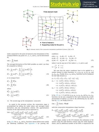
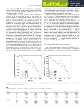
Figs. 3a and 3b show a comparison of the 1D shape functions
and their first-order derivatives between the FEM and CFEM
methods. It is observed in the figures that the curves of the CFEM
shape functions and their derivatives are rather smooth and
continuous as compared with those based on the FEM. The 2D
shape functions derived from the Q4 and CQ4 elements are also
visualized in Fig. 3c and d. Nevertheless, some important and
desirable properties of the CFEM shape functions may be sum-
marized as follows:
(a) The approximation functions or the shape functions do not
include any rational terms, and as a result they are advanta-
geous for an accurate integration of the stiffness matrix.
(b) The shape functions have high-order continuities, i.e., C1
inside the elements, C1
on nodes and C0
on the element edges.
It is also noted that some nodes, for instance the nodes located
on the essential boundary or on the interface of bi-materials,
are required for the CQ4 to recover to a C0
continuity. Hence a
slight modification may be made on those nodes [7]. The CFEM
will be degenerated into the FEM if all the nodes in the
problem domain are supposed to be C0
.
(c) Since the consecutive-interpolation passing through nodal
values, the shape functions are hence said to be satisfied the
Kronecker-delta function property.
(d) The consecutive-interpolation is said to be linear consistency
as it can exactly reproduce any functions in the basis functions
i.e., ∑ns
i ¼ 1
~
NiðxÞ ¼ 1; ∑ns
i ¼ 1
~
NiðxÞxi ¼ x; ∑ns
i ¼ 1
~
NiðxÞyi ¼ y.
3.4. Stiffness matrix and numerical integration
Before describing the stiffness matrix implementation and the
numerical integration of the proposed CQ4 element, it must be
stated here that the approximation function of the displacements
using the FEM in Eq. (4) and the CFEM in Eq. (26) has a similar
form. The only difference between them is the way of the
construction of their shape functions. Therefore, the discrete
equations derived from the weak-form in Eq. (3) shall be the same
for both the FEM and the CFEM. As a result the element stiffness
matrix Ke can be finally expressed as [1–3].
Ke ¼
Z
Ωe
BT
e DBe dΩ ð28Þ
In Eq. (28), the domain Ωe is different between the FEM and the
CFEM, which fully depends on the supporting nodes and neigh-
boring elements determined by the CFEM procedure. The matrix of
the derivative of the shape functions Be is also different between
the FEM and the CFEM. Obviously, the difference can be depicted
explicitly, for instance, let us consider a quadrilateral element with
Fig. 3. Comparison of the shape functions (a) and their first-order derivatives (b) in 1D classical and consecutive FEM. Visualization of the shape functions: Q4 (c) and CQ4
(d) elements.
T.Q. Bui et al. / Finite Elements in Analysis and Design 84 (2014) 14–31
18
6. four-node presented in this study, the matrix Be obtained by the
FEM method can be expressed as
BFEM
e ¼
∂Ni
∂x
∂Nj
∂x
∂Nk
∂x
∂Nm
∂x 0 0 0 0
0 0 0 0 ∂Ni
∂y
∂Nj
∂y
∂Nk
∂y
∂Nm
∂y
∂Ni
∂y
∂Nj
∂y
∂Nk
∂y
∂Nm
∂y
∂Ni
∂x
∂Nj
∂x
∂Nk
∂x
∂Nm
∂x
2
6
6
6
4
3
7
7
7
5
ð38Þ
ð29Þ
and the same but by the CFEM
BCFEM
e ¼
∂ ~
N1
∂x
∂ ~
N2
∂x ⋯ ∂ ~
Nl
∂x ⋯
∂ ~
Nns
∂x 0 0 ⋯ 0 ⋯ 0
0 0 ⋯ 0 ⋯ 0 ∂ ~
N1
∂y
∂ ~
N2
∂y ⋯ ∂ ~
Nl
∂y ⋯
∂ ~
Nns
∂y
∂ ~
N1
∂y
∂ ~
N2
∂y ⋯ ∂ ~
Nl
∂y ⋯
∂ ~
Nns
∂y
∂ ~
N1
∂x
∂ ~
N2
∂x ⋯ ∂ ~
Nl
∂x ⋯
∂ ~
Nns
∂x
2
6
6
6
6
4
3
7
7
7
7
5
ð32nsÞ
ð30Þ
In Eq. (30), ns is the number of the supporting nodes, 1olons
and ns 44. It is because that the displacements in the CFEM are
not only interpolated from the nodal displacements of the con-
sidered element, but also interpolated from the supporting nodes
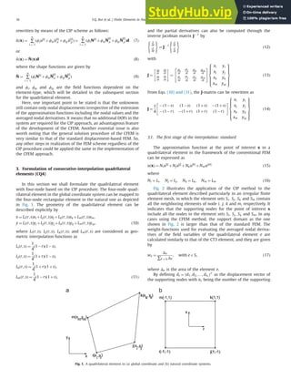
determined by other neighboring elements, as sketched in Fig. 2.
The size of the matrix BFEM
e is of ð3 8Þ and that is much smaller
than the size of the matrix BCFEM
e , ð3 2nsÞ, which results in an
increased bandwidth of the stiffness matrix of the CFEM.
In the above equations the derivative of the CFEM shape
functions is calculated by
∂ ~
Nl
∂z
¼
∂ϕi
∂z
N i
½ Š
l
þ
∂ϕix
∂z
N
i
½ Š
l;x þ
∂ϕiy
∂z
N
i
½ Š
l;y
|fflfflfflfflfflfflfflfflfflfflfflfflfflfflfflfflfflfflfflfflfflfflffl{zfflfflfflfflfflfflfflfflfflfflfflfflfflfflfflfflfflfflfflfflfflfflffl}
related to node i
þ
∂ϕj
∂z
N j
½ Š
l
þ
∂ϕjx
∂z
N
j
½ Š
l;x þ
∂ϕjy
∂z
N
j
½ Š
l;y
|fflfflfflfflfflfflfflfflfflfflfflfflfflfflfflfflfflfflfflfflfflfflffl{zfflfflfflfflfflfflfflfflfflfflfflfflfflfflfflfflfflfflfflfflfflfflffl}
node j
þ
∂ϕk
∂z
N
k
½ Š
l
þ
∂ϕkx
∂z
N
k
½ Š
l;x þ
∂ϕky
∂z
N
k
½ Š
l;y
|fflfflfflfflfflfflfflfflfflfflfflfflfflfflfflfflfflfflfflfflfflfflfflfflfflffl{zfflfflfflfflfflfflfflfflfflfflfflfflfflfflfflfflfflfflfflfflfflfflfflfflfflffl}
node k
þ
∂ϕm
∂z
N m
½ Š
l
þ
∂ϕmx
∂z
N
m
½ Š
l;x þ
∂ϕmy
∂z
N
m
½ Š
l;y
|fflfflfflfflfflfflfflfflfflfflfflfflfflfflfflfflfflfflfflfflfflfflfflfflfflfflfflffl{zfflfflfflfflfflfflfflfflfflfflfflfflfflfflfflfflfflfflfflfflfflfflfflfflfflfflfflffl}
node m
ð31Þ
with z ¼ x; y.
In order to perform the numerical integration of the stiffness
matrix of the CFEM method, we adopt a set of 3 3 Gaussian
quadrature points for all the implementations throughout the
study. It is because, in general, the implementation of the
numerical integration in the CFEM is realized similar to that in
the conventional FEM. None of any special techniques is required
for the numerical integrations of the CQ4 element. Any quadrature
rules used for the FEM can be applied the same for the CFEM, but it
may obey the relation of the number of Gaussian points ngp with
respect to the polynomial of order p as indicated in Ref. [2], i.e.,
pr2ngp 1. Nonetheless, the variation and the influence of the
Gauss quadrature rules on the accuracy of the solutions shall be
studied numerically in the numerical example part. This is
accomplished by considering the first six two-dimensional Gaus-
sian quadrature rules from 1 1 to 6 6 respectively, and the two
error indicators in the displacement and energy norms, as well as
the maximum and minimum values of the von Mises stresses will
be investigated accordingly.
4. Numerical examples
In this section four benchmark numerical examples are exam-
ined to show the accuracy, the efficiency and the convergence of
the present CQ4 element. In addition, other two examples are
considered as practical applications to illustrate the applicability of
the proposed CQ4 element in dealing with complex geometries.
The materials used for all the four benchmark examples are
assumed to be linear elastic with Young's modulus E ¼ 1000 and
Poisson's ratio ν ¼ 0:3, whereas they are specified thereafter for
the two practical examples. The units used in the examples can be
any consistent unit based on the international standard unit
system, if not specified otherwise. To accomplish the convergence
study, two error indicators with respect to the displacement and
energy norms are defined as follows: [19,20]
ed ¼
ffiffiffiffiffiffiffiffiffiffiffiffiffiffiffiffiffiffiffiffiffiffiffiffiffiffiffiffiffiffiffiffiffiffiffiffiffiffiffiffiffiffiffiffiffiffiffi
∑n
i ¼ 1ðuexact
i unumer
i Þ2
∑n
i ¼ 1ðuexact
i Þ2
v
u
u
t ; ð32Þ
ee ¼
1
A
ffiffiffiffiffiffiffiffiffiffiffiffiffiffiffiffiffiffiffiffiffiffiffiffiffiffiffiffiffiffiffiffiffiffiffiffiffiffiffiffiffiffiffiffiffiffiffiffiffiffiffiffiffiffiffiffiffiffiffiffiffiffiffiffiffiffiffiffiffiffiffiffiffiffiffiffiffiffiffiffiffiffiffi
1
2
Z
Ω
ðεexact εnumerÞT
Dðεexact εnumerÞdΩ
s
; ð33Þ
where the superscript “exact” represents the analytical solutions
while “numer” stands for the numerical solutions, and A is the area
of the problem domain.
4.1. Standard patch test
The satisfaction of the standard patch test in general requires
the displacement fields of all the interior nodes of the patch that
follow “exactly” the same linear functions of the imposed dis-
placements on its boundaries [20]. As a consequence a sufficient
condition for the convergence of a numerical method is to
precisely pass such standard patch test. A 1 1 unit square
domain of a patch test discretized by 4 4 regular and irregular
quadrilateral elements with four-node as shown in Fig. 4 is
studied using the CFEM. The displacements are prescribed on all
boundaries by the following linear functions:
ux ¼ x;
Fig. 4. Domain discretization of a unit square patch test using the CQ4 elements: regular (a) and irregular (b) meshes.
T.Q. Bui et al. / Finite Elements in Analysis and Design 84 (2014) 14–31 19
7. uy ¼ y ð34Þ
The relative errors in the displacement norm ed are found to be
2:0761e 016 and 2:4855e 016 for the regular and irregular
meshes, respectively. As a result, these error results indicate
that the present CQ4 element passes the standard patch test
successfully.
4.2. Cantilever beam
A cantilever beam with length L ¼ 8 and height D ¼ 2 subjected
to a parabolic traction on the right end as depicted in Fig. 5 is
considered. The cantilever is assumed to have a unit thickness and
the corresponding analytical solutions of the displacements and
stresses based on the plane-stress condition are given by [21]
ux ¼
Py
6EI
ð6L 3xÞxþð2þνÞ y2 D2
4
!
#
;
uy ¼
P
6EI
3νy2
ðL xÞþð4þ5νÞ
D2
x
4
þð3L xÞx2
#
; ð35Þ
sx ¼ P L x
ð Þy
I ;
sy ¼ 0;
τxy ¼
P
2I
D2
4
y2
#
ð36Þ
where I ¼ D3
=12 is the moment of inertia of the cantilever beam.
For the plane-strain problem, E and ν in Eqs. (35) and (36) are
replaced by E=ð1 ν2
Þ and ν=ð1 νÞ, respectively, and P ¼ 2.
To serve the validation purpose, four elements listed in the
following are considered:
(a) the CIP-based quadrilateral element with four-node: CQ4
(b) the CIP-based triangular element: CT3 [7]
(c) the standard quadrilateral element with four-node: Q4
(d) the standard triangular element with three-node: T3
The convergence rate of all the aforementioned elements is
analyzed using both the regular and distorted meshes. However,
Fig. 5. Geometry of a cantilever beam subjected to a parabolic traction on the
right end.
Fig. 6. Three discretized regular (a) and distorted (b) meshes using quadrilateral elements for a cantilever beam.
Fig. 7. Comparison of the convergence rates for a cantilever beam using the regular meshes obtained by the CQ4, CT3, Q4 and T3 elements: relative errors in displacement
norm (a) and energy norm (b).
T.Q. Bui et al. / Finite Elements in Analysis and Design 84 (2014) 14–31
20
8. only the regular and irregular meshes of 9 5, 16 10 and 30
20 quadrilateral elements with four-node are depicted in Fig. 6,
and the meshes discretized by using the triangular elements of the
CT3 and T3 elements are omitted for the brevity. Fig. 7 illustrates
the convergence rates in both the energy and displacement norms
using the regular meshes with respect to the nodal ratio h (e.g.,
h ¼ 1=9, 1/16, 1/30, 1/60) obtained by the CQ4, Q4, CT3, and T3
elements. It reveals in the figures that the proposed CQ4 element
outperforms the T3 and Q4 elements as well as the CT3 once the
mesh is further refined. In terms of the accuracy, the CFEM
provides much better results than the FEM and the CQ4 element
performs the best. Further study of the convergence rate is
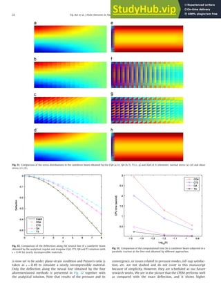
conducted using the distorted meshes, and their obtained con-
vergence rates in both the displacement and energy norms are
then sketched in Fig. 8. Similar convergence rates for both the
regular and distorted meshes are gained and, not surprisingly, the
regular mesh desirably yields higher accuracy than the irregular
one, as usual. However, the obtained results indicate that the
irregular mesh has only a little effect on the accuracy.
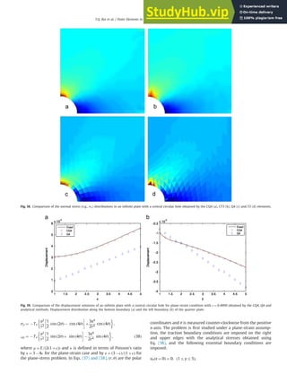
To investigate the accuracy of the developed CQ4 element, the
beam is discretized using both the regular and irregular meshes of
16 10 elements. The numerical results of the displacement in y-
direction along the neutral line and the shear stress along the
middle line are obtained using the CQ4 (regular and irregular
meshes), CT3, Q4 and T3 elements, and plotted in Figs. 9 and 10,
respectively. The figures exhibit that the displacement and stress
components obtained by the CQ4 and CT3 are all in good agree-
ment with the analytical ones, whereas less accuracy can be found
for the Q4 and T3 elements. For a better representation, the
normal and shear stress distributions (e.g., sx, τxy) obtained by
the CQ4, Q4, T3 and SQ4 elements are depicted in Fig. 11.
Obviously, the stresses achieved by the Q4 and T3 elements are
discontinuous and non-smooth whilst the developed CQ4 element
works well, i.e., the stresses are continuous and smooth. It should
be recalled that the developed CFEM is very smooth though no
post-processing is performed.
In Fig. 11, the SQ4 element is the standard Q4 but its final
results (see Fig. 11d and h) are smoothed out by further applying a
smoothing stress recovery technique in the post-processing step.
These SQ4 results are motivated since it may be interesting to see
how smooth on the stresses obtained by the present CFEM method
and the one using the stress recovery technique as usually done in
practice. By accomplishing that, we merely adopt one of the
simplest stress recovery techniques that have been found most
useful in practice, the averaged nodal stresses [22]. The realization
of this so-called unweighted averaging is carried out by assigning
the same weight to all elements that meet at a node. It is obvious
that the SQ4 results are as smooth as the CQ4 ones.
To check the ability of the present CFEM in treating the volume
locking phenomenon in the incompressible materials (i.e.,
Poisson's ratio tends toward 0.5), the same problem but the beam
Fig. 8. Comparison of the convergence rates for a cantilever beam using the regular and distorted meshes obtained by the present CQ4 element: relative errors in
displacement norm (a) and energy norm (b).
Fig. 9. Comparison of the deflections along the neutral line of a cantilever beam
obtained by the analytical, regular and irregular CQ4, CT3, Q4 and T3 solutions. Fig. 10. Comparison of the shear stress distributions along the line (x¼L/2) of a
cantilever beam obtained by the analytical, regular and irregular CQ4, CT3, Q4 and
T3 solutions.
T.Q. Bui et al. / Finite Elements in Analysis and Design 84 (2014) 14–31 21
9. is now set to be under plane-strain condition and Poison's ratio is
taken as ν ¼ 0:49 to simulate a nearly incompressible material.
Only the deflection along the neural line obtained by the four
aforementioned methods is presented in Fig. 12 together with
the analytical solution. Note that results of the pressure and its
convergence, or issues related to pressure modes, inf–sup satisfac-
tion, etc. are not studied and do not cover in this manuscript
because of simplicity. However, they are scheduled as our future
research works. We see in the picture that the CFEM performs well
as compared with the exact deflection, and it shows higher
Fig. 11. Comparison of the stress distributions in the cantilever beam obtained by the CQ4 (a, e); Q4 (b, f); T3 (c, g) and SQ4 (d, h) elements: normal stress (a)–(d) and shear
stress (e)–(h).
Fig. 12. Comparison of the deflections along the neutral line of a cantilever beam
obtained by the analytical, regular and irregular CQ4, CT3, Q4 and T3 solutions with
ν ¼ 0:49 for nearly incompressible materials.
Fig. 13. Comparison of the computational time for a cantilever beam subjected to a
parabolic traction at the free-end obtained by different approaches.
T.Q. Bui et al. / Finite Elements in Analysis and Design 84 (2014) 14–31
22
10. accuracy than the FEM. More importantly, based on these pre-
liminary results it may be stated that the nearly incompressible
materials can be treated by the CFEM with high accuracy, and the
volumetric locking is alleviated.
Another important issue in relevance to the computational
efficiency of the developed CQ4 element is also studied. The
computational time needed for the T3, Q4, CT3 and CQ4 elements
tested on three different meshes of 9 5, 16 10 and 30 20
elements, is investigated. Here, only the time required for the
computation of the global stiffness matrix is measured and
estimated. It is because that the most difference among the
aforementioned methods is induced by the implementation of
the stiffness matrix, which substantially pertains to the difference
of establishing the shape functions and their derivatives. The
comparison is performed on the same PC of Intel(R)
Pentium(R)
Dual-Core 2.6 GHz, 2.GB RAM. 5 calculations are carried out for
each mesh and the averaged computational time is then reported.
Fig. 13 shows the required CPU time of different approaches using
the same direct solver. Because of an extra task of the consecutive-
interpolation implementation of the shape functions and their
derivatives, the CQ4 and CT3 elements obviously require more
time than the standard Q4 and T3 ones. On the other hand, the
computational efficiency in terms of the relative errors in both the
displacement and energy norms against the computational time
(in seconds) is compared and depicted in Fig. 14 under a log–log
plot. It is evident that with respect to the computational efficiency
(computational time for the same accuracy) the CFEM is more
efficient as clearly shown in the relative error results in compar-
ison with the FEM. From the practical point of view, it should be
noted that to achieve acceptable solutions by using the standard
FEM, demanding post-processing is often required and it may be a
time-consuming task. In fact, it is difficult and/or even impossible
to estimate how much time such task would take.
Furthermore, as mentioned in Section 3.4, we now study numeri-
cally the effect of the Gaussian quadrature rules on the numerical
results of the beam. This investigation is carried out by considering
the first six two-dimensional Gaussian quadrature rules from 1 1
to 6 6, and the two error indicators in the displacement (ed) and
energy (ee) norms as well as the maximum and minimum values
(smax,smin) of the von Mises stresses are estimated and explored.
Two regular meshes of 16 8 and 32 16 discretized for the beam
are considered. The corresponding obtained results are tabulated in
Table 1. We observe in the table that as usual high error and less
accuracy can be found for the quadrature rule of 1 1, and the
results are similar for other quadrature rules. It implies that higher
number of the Gaussian quadrature rules does not influence too
much on the accuracy of the results, but it may increase the
computational time. As expected, the errors obtained by the finer
mesh are found to be smaller than that by the coarser one. As a result
we decide to use a set of 3 3 Gaussian quadrature rule for all the
implementations throughout the study.
4.3. An infinite plate with a central circular hole
Next benchmark example considers an infinite plate with a
central circular hole of radius a and subjected to a unidirectional
tensile loading Tx ¼ 1 as depicted in Fig. 15a. Only one quarter of
Fig. 14. Comparison of the computational efficiency in terms of displacement (a) and energy (b) error norms for a cantilever beam subjected to a parabolic traction at the
free-end obtained by different approaches.
Table 1
Variation and the effect of the Gaussian quadrature rules on the numerical results of the cantilever beam.
Mesh 1 1 2 2 3 3 4 4 5 5 6 6
16 8 smax 24.0883 23.2061 23.1883 23.1863 23.1863 23.1863
smin 1.0232 0.8472 0.8562 0.8563 0.8563 0.8563
ed 0.0169 0.0021 0.0019 0.0019 0.0019 0.0019
ee 0.0188 0.0446 0.0434 0.0442 0.0442 0.0442
32 16 smax 23.818 23.5251 23.5174 23.5165 23.5165 23.5165
smin 0.5771 0.4586 0.4543 0.4543 0.4543 0.4543
ed 0.0042 0.00027 0.00025 0.00026 0.00026 0.00026
ee 0.0051 0.0161 0.0155 0.0158 0.0158 0.0158
T.Q. Bui et al. / Finite Elements in Analysis and Design 84 (2014) 14–31 23
11. the plate (b ¼ 5; a ¼ 1) shown in Fig. 15b is modeled due to the
two-fold symmetry. The analytical solutions of the displacement
and stress fields of the infinite plate are given by [21]
ur ¼
Tx
4μ
r
ðκ 1Þ
2
þ cos ð2θÞ
þ
a2
r
½1þð1þκÞ cos ð2θÞŠ
a4
r3
cos ð2θÞ
;
uθ ¼
Tx
4μ
ð1 κÞ
a2
r
r
a4
r3
sin ð2θÞ; ð37Þ
sx ¼ Tx 1
a2
r2
3
2
cos ð2θÞþ cos ð4θÞ
þ
3a4
2r4
cos ð4θÞ
;
Fig. 15. Geometry of an infinite plate with a central circular hole (a) and its quarter model (b).
Fig. 16. Comparison of the convergence rates for an infinite plate with a circular hole obtained by the CQ4, CT3, Q4 and T3 elements: relative errors in displacement norm
(a) and energy norm (b).
Fig. 17. Comparison of the stress distributions along the left boundary (a) and the bottom boundary (b) of the quarter plate with a circular hole subjected to a unidirectional
tension.
T.Q. Bui et al. / Finite Elements in Analysis and Design 84 (2014) 14–31
24
12. sy ¼ Tx
a2
r2
1
2
cos ð2θÞ cos ð4θÞ
þ
3a4
2r4
cos ð4θÞ
;
τxy ¼ Tx
a2
r2
1
2
sin ð2θÞþ sin ð4θÞ
3a4
2r4
sin ð4θÞ
; ð38Þ
where μ ¼ E=ð2ð1þνÞÞ and κ is defined in terms of Poisson's ratio
by κ ¼ 3 4ν for the plane-strain case and by κ ¼ ð3 νÞ=ð1þνÞ for
the plane-stress problem. In Eqs. (37) and (38), ðr; θÞ are the polar
coordinates and θ is measured counter-clockwise from the positive
x-axis. The problem is first studied under a plane-strain assump-
tion, the traction boundary conditions are imposed on the right
and upper edges with the analytical stresses obtained using
Eq. (38), and the following essential boundary conditions are
imposed:
uxðx ¼ 0Þ ¼ 0; ð1ryr5Þ;
Fig. 18. Comparison of the normal stress (e.g., sx) distributions in an infinite plate with a central circular hole obtained by the CQ4 (a), CT3 (b), Q4 (c) and T3 (d) elements.
Fig. 19. Comparison of the displacement solutions of an infinite plate with a central circular hole for plane-strain condition with ν ¼ 0:4999 obtained by the CQ4, Q4 and
analytical methods. Displacement distribution along the bottom boundary (a) and the left boundary (b) of the quarter plate.
T.Q. Bui et al. / Finite Elements in Analysis and Design 84 (2014) 14–31 25
13. uyðy ¼ 0Þ ¼ 0; ð1rxr5Þ ð39Þ
Similar to the previous beam example, the convergence study is
presented. Fig. 16 essentially shows the convergence rate in both
the energy and displacement norms using a regular mesh with
respect to the nodal ratio h (e.g., h ¼ 1=7, 1/13, 1/25) for different
approaches. The obtained results of the convergence rate are not
surprising, and as expected the developed CQ4 outperforms the
CT3, T3 and Q4 elements when a mesh refinement is made. The
CFEM provides much better results than the FEM as clearly seen in
their relative errors in both the displacement and energy norms,
and here again the present CQ4 is the winner.
In terms of the accuracy, Fig. 17 further provides us a compar-
ison of the stress distributions along the left and bottom
Fig. 20. Geometry of internally pressurized hollow cylinder (a) and its quarter model.
Fig. 21. Regular (a) and irregular (b) meshes of 12 12 quadrilateral elements.
Fig. 22. Comparison of the convergence rates of an internally pressurized hollow cylinder hole obtained by the CQ4, CT3, Q4 and T3 elements: relative errors in displacement
norm (a) and energy norm (b).
T.Q. Bui et al. / Finite Elements in Analysis and Design 84 (2014) 14–31
26
14. boundaries of the quarter plate obtained by the CQ4 element using
a regular mesh of 13 13 elements, and by the analytical solu-
tions. The CFEM matches well with the exact solutions. Addition-
ally, Fig. 18 shows the normal stress distributions of an infinite
plate obtained, respectively, by the CQ4, CT3, Q4 and T3 elements.
It is again observed that the stresses obtained by the CFEM are
continuous and smooth whereas the standard FEM does not
guarantee such smoothness and continuity.
Similarly, the volumetric locking phenomenon is again ana-
lyzed numerically using a regular mesh of 13 13 elements with
Poisson's ratio taken to be ν ¼ 0:4999. Fig. 19 shows a comparison
of the displacement distributions along the bottom (Fig. 19a) and
left (Fig. 19b) boundaries of the quarter plate obtained by the
present CQ4, the Q4 and the analytical approaches. It shows that
the CFEM can still achieve better results with a Poisson's ratio
ν ¼ 0:4999 while large errors are found for the standard Q4
element using the same mesh.
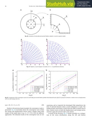
4.4. Hollow cylinder under internal pressure
Another benchmark example considers a hollow cylinder sub-
jected to an internal pressure as depicted in Fig. 20 to further show
the accuracy of the CFEM. The cylinder is designed with an inner
radius of a, an outer radius of b and a unit thickness. A uniform
pressure of p is applied to the inner surface at r ¼ a, whilst
traction-free boundary condition is assigned at the outer surface
r ¼ b. Only one-quarter of the cylinder is modeled due to the
geometrical symmetry of the structure. The analytical solutions of
the displacement and stress fields of this internally pressurized
hollow cylinder are available and given by [21].
urðrÞ ¼
a2
pr
Eðb
2
a2Þ
1 νþ
b
2
r2
ð1þνÞ
#
;
uθ ¼ 0; ð40Þ
srðrÞ ¼
a2
p
ðb
2
a2Þ
1
b
2
r2
#
;
sθðrÞ ¼
a2
p
ðb
2
a2Þ
1þ
b
2
r2
#
;
τrθ ¼ 0 ð41Þ
In the numerical investigation, the following parameters are
used: a ¼ 1, b ¼ 5, p ¼ 1, and the plane-stress condition is assumed.
We first explore the convergence rate of the different methods by
considering three regular and three irregular meshes of 6 6,
12 12, 22 22 and 32 32 elements. Only the case of the
regular and distorted meshes with 12 12 elements is shown in
Fig. 21. Fig. 22 shows a comparison of the convergence rates in
both the energy and displacement norms with respect to the nodal
ratio h (e.g., h ¼ 1=7, 1/13, 1/23, 1/33) obtained by the CQ4, CT3, Q4
and T3 elements. Again and similar to the previous examples, the
numerical results clearly confirm the high accuracy and conver-
gence rate of the present CFEM.
For the accuracy study, the problem is discretized by using the
regular and irregular meshes with 12 12 elements, and the
obtained numerical solutions using several aforementioned meth-
ods are plotted in Figs. 23 and 24 for the displacement and stress
fields, respectively. The results obtained by the CFEM agree well
with the analytical solutions, but the standard FEM yields less
accuracy. The radial stress component sr derived by the four
approaches is also depicted in Fig. 25 and one clearly observes in
the figures that the CFEM provides much smoother stresses than
the FEM using the same mesh.
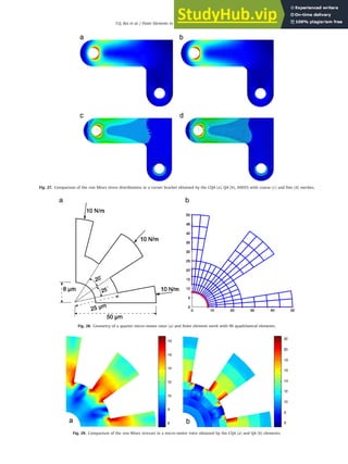
4.5. Practical example: corner bracket
The major objective of the subsequent numerical examples is to
further demonstrate the applicability of the CFEM method to the
problems of complex geometry. The first practical example considers a
corner angle bracket with its geometry as depicted in Fig. 26a. The
corner bracket is popularly used in many engineering applications.
The bracket in this study is made of steel with a Young's modulus of
206.84 GPa, Poisson's ratio of 0.27, and the plane-stress condition is
assumed [23]. The upper left-hand pin hole is constrained around its
entire circumference, and a tapered pressure load is applied to the
bottom of the lower right-hand hole. The corner bracket is discretized
with irregular meshes (see Fig. 26b) using the present CQ4, the Q4
elements, and ANSYS with the PLANE42 element. The results com-
puted by the ANSYS are used here as a reference solution, and the
bracket is discretized with different refinements using the standard 4-
node element starting from approximately 700 elements up to almost
16,000 elements. A maximum value of the von Mises stress of
19.705 MPa is obtained for a fine mesh. On the other hand, the
Fig. 23. Displacement distribution along the boundary line x¼0 of an internally
pressurized hollow cylinder.
Fig. 24. Stress distributions along the boundary line x¼0 of an internally
pressurized hollow cylinder.
T.Q. Bui et al. / Finite Elements in Analysis and Design 84 (2014) 14–31 27
15. bracket is also discretized by an irregular mesh of 1282 elements (see
Fig. 26b) using quadrilateral elements. The maximum von Mises
stresses are obtained, respectively, as 19.8817 MPa by the CQ4 and
20.2707 MPa by the Q4 elements. As compared with the ANSYS-based
von Mises value, one can see that the calculated CQ4 solution is closer
than that of the Q4 element for the same mesh. Fig. 27 depicts the
distribution of the von Mises stresses in the bracket by the CQ4 (a), Q4
(b) and ANSYS1
using PLANE42 with course (c) and fine (d) meshes.
A very good agreement in the stress distributions obtained by different
approaches is found. However, the CQ4 element again provides much
smoother stresses than the Q4 element.
4.6. Practical example: rotor of a micro-motor
Finally, a common micro-actuator in the form of a side-driving
electrostatic micro-motor used in MEMs devices is analyzed [3].
Such micro-motor is usually made from polysilicon using litho-
graphic techniques. The material parameters of the polysilicon are
Young's modulus of 169 GPa and Poisson's ratio of 0.262. Isotropic
material properties are employed to simplify the problem. A real
model of the micro-rotor can be found in Ref. [3], and due to its
Fig. 25. Comparison of the radial stress (e.g., sr) of an internally pressurized hollow cylinder obtained by the CQ4 (a), CT3 (b), Q4 (c) and T3 (d) elements.
Fig. 26. Geometry of a corner angle bracket (a) and its finite element mesh (b).
1
Note that we use the ANSYS's command such as (PLESOL, S, EQV) to plot the
stresses.
T.Q. Bui et al. / Finite Elements in Analysis and Design 84 (2014) 14–31
28
16. Fig. 27. Comparison of the von Mises stress distributions in a corner bracket obtained by the CQ4 (a), Q4 (b), ANSYS with coarse (c) and fine (d) meshes.
Fig. 28. Geometry of a quarter micro-motor rotor (a) and finite element mesh with 96 quadrilateral elements.
Fig. 29. Comparison of the von Mises stresses in a micro-motor rotor obtained by the CQ4 (a) and Q4 (b) elements.
T.Q. Bui et al. / Finite Elements in Analysis and Design 84 (2014) 14–31 29
17. symmetry only one quarter with the corresponding boundary
conditions as depicted in Fig. 28a is taken. Typically, a finite
element mesh of the domain discretized by 96 quadrilateral
elements with four-node is depicted in Fig. 28b. Similar to the
bracket example, reference solutions are also derived from the
FEM using ANSYS. Thus, different refinements from a coarse mesh
to a very fine one are performed, and the maximum von Mises
stress at the corners of the rotor obtained by ANSYS using a very
fine mesh is 18.832 MPa. The solutions computed by the CQ4 and
Q4 elements, respectively, are 18.837 MPa and 22.599 MPa, and as
a result it again reveals the high accuracy of the CFEM. Fig. 29
similarly shows the von Mises stress distributions in the rotor
obtained by the CQ4 (a) and Q4 (b) elements, respectively, and
smoother stresses are achieved by using the CFEM rather than the
FEM for the same mesh.
5. Conclusions
An efficient and accurate quadrilateral element with four-node
based on the CIP is formulated. The developed CQ4 element is
applied to the stress analysis of 2D elastic structures. The advan-
tages of the CFEM are due to the fact that the stresses and strains
at nodes are continuous, smooth and it requires no smoothing
operation in the post-processing step. From the numerical results
of the four benchmark examples, it confirms the high accuracy of
the CFEM that pertains to high convergence rate as compared with
the standard FEM (Q4, T3) and even the CT3. Highly accurate
results in the practical examples further confirm the applicability
of the present CFEM in the stress analysis of 2D elastic structures
with complex configuration. The CIP algorithm is general and has
no limitations on its extension to other elements such as tetra-
hedral and brick elements in 3D. The extension of the method is
also attractive to the incompressible media, in which some
relevant issues pertaining to the pressure modes, convergence,
the inf–sup satisfaction, etc. should be investigated and addressed
in detail. From the present research work, the following conclu-
sions can be drawn:
The shape functions of the present CQ4 element are higher-
order polynomials and possess the Kronecker-delta function
property, which allows a straightforward imposition of the
essential boundary conditions.
As compared with the traditional FEM (Q4, T3) and even the
CT3 element, the CQ4 substantially pertains to higher accuracy,
higher efficiency and higher convergence rate. Specially, nodal
stresses are generated continuously without any smoothing
operation; mesh distortions are insensitive; based on the
preliminary results it shows that the volumetric locking is
alleviated in incompressible materials; and without the
increase of the DOFs in the system.
The present CFEM method is straightforwardly implemented in
any existing computer FEM code.
No post-processing is required in the CFEM.
Acknowledgment
The support of the German Academic Exchange Service (DAAD,
Project-ID: 54368781) is gratefully acknowledged.
Appendix A
As stated above that the ϕi; ϕix; and ϕiy functions in Eq. (25)
must satisfy the conditions in Eq. (23), hence we shall present it in
this Appendix.
Let us consider a quadrilateral element with four-node as
sketched in Fig. 1. The geometric interpolation functions are given
in Eq. (11). For convenience in representation, the derivatives of
Eq. (11) are
∂
∂r
∂
∂s
( )
Li Lj Lk Lm
h i
¼
1
4
ð1 sÞ ð1 sÞ ð1þsÞ ð1þsÞ
ð1 rÞ ð1þrÞ ð1þrÞ ð1 rÞ
#
ðA1Þ
The Jacobian matrix and its inverse are explicitly expressed as
J ¼
1
4
ð1 sÞ ð1 sÞ ð1þsÞ ð1þsÞ
ð1 rÞ ð1þrÞ ð1þrÞ ð1 rÞ
#
xi yi
xj yj
xk yk
xm ym
8
:
9
=
;
ðA2Þ
J 1
¼
1
4detðJÞ
J1 J2
J3 J4
#
with J1 ¼ yið1 rÞ yjð1þrÞþykð1þrÞþymð1 rÞ;
J2 ¼ yið1 sÞ yjð1 sÞ ykð1þsÞþymð1þsÞ;
J3 ¼ xið1 rÞþxjð1þrÞ xkð1þrÞ xmð1 rÞ;
J4 ¼ xið1 sÞþxjð1 sÞþxkð1þsÞ xmð1þsÞ ðA3Þ
First, the derivatives of the geometric interpolation functions can
be expressed as
∂ϕi
∂Li
¼ 1þ2LiLj þ2LiLk þ2LiLm L2
j L2
k L2
m;
∂ϕi
∂Lj
¼ L2
i 2LiLj;
∂ϕi
∂Lk
¼ L2
i 2LiLk;
∂ϕi
∂Lm
¼ L2
i 2LiLm
∂ϕix
∂Li
¼ ðxi xjÞð2LiLj þpLjLk þpLjLmÞ
ðxi xkÞð2LiLk þpLkLm þpLkLjÞ
ðxi xmÞð2LiLm þpLmLj þpLmLkÞ;
∂ϕix
∂Lj
¼ ðxi xjÞðL2
i þpLiLk þpLiLmÞ
ðxi xkÞðpLiLkÞ ðxi xmÞðpLiLmÞ;
∂ϕix
∂Lk
¼ ðxi xjÞðpLiLjÞ ðxi xkÞðL2
i þpLiLm þpLiLjÞ
ðxi xmÞðpLiLmÞ;
∂ϕix
∂Lm
¼ ðxi xjÞðpLiLjÞ ðxi xkÞðpLiLkÞ
ðxi xmÞðL2
i þpLiLj þpLiLkÞ;
∂ϕiy
∂Li
¼ ðyi yjÞð2LiLj þpLjLk þpLjLmÞ
ðyi ykÞð2LiLk þpLkLm þpLkLjÞ
ðyi ymÞð2LiLm þpLmLj þpLmLkÞ;
∂ϕiy
∂Lj
¼ ðyi yjÞðL2
i þpLiLk þpLiLmÞ
ðyi ykÞðpLiLkÞ ðyi ymÞðpLiLmÞ;
∂ϕiy
∂Lk
¼ ðyi yjÞðpLiLjÞ ðyi ykÞðL2
i þpLiLm þpLiLjÞ
ðyi ymÞðpLiLmÞ;
∂ϕiy
∂Lm
¼ ðyi yjÞðpLiLjÞ ðyi ykÞðpLiLkÞ
ðyi ymÞðL2
i þpLiLj þpLiLkÞ ðA4Þ
Now, we prove the condition: ϕiðxlÞ ¼ δil. When l i, then
r ¼ 1; s ¼ 1 and Li ¼ 1; Lj ¼ Lk ¼ Lm ¼ 0, substituting them into
Eqs. (11) and (25), we obtain: ϕiðxiÞ ¼ 1. Similarly, when l j; l k;
or l m, we respectively obtain ϕiðxjÞ ¼ 0; ϕiðxkÞ ¼ 0 and ϕi xm
ð Þ ¼ 0.
Next, we prove the conditions: ϕi;xðxlÞ ¼ 0, ϕi;yðxlÞ ¼ 0.
T.Q. Bui et al. / Finite Elements in Analysis and Design 84 (2014) 14–31
30
18. When l i, then r ¼ 1; s ¼ 1 and Li ¼ 1; Lj ¼ Lk ¼ Lm ¼ 0.
Substituting them into Eqs. (A1) and (A3), we have
∂
∂r
∂
∂s
( )
Li Lj Lk Lm
h i
¼
1
4
2 2 0 0
2 0 0 2
;
J 1
¼
1
4detðJÞ
2yi þ2ym 2yi 2yj
2xi 2xm 2xi þ2xj
#
;
∂
∂x
∂
∂y
( )
Li Lj Lk Lm
h i
¼ J 1
∂
∂r
∂
∂s
( )
Li Lj Lk Lm
h i
¼
1
4detðJÞ
2yi þ2ym 2yi 2yj
2xi 2xm 2xi þ2xj
#
1
4
2 2 0 0
2 0 0 2
¼
1
4detðJÞ
yj ym ym yi 0 yi yj
xm xj xi xm 0 xj xi
#
ðA5Þ
and into the first sub-equations of Eq. (A4)
∂ϕ
∂Li
¼ 1;
∂ϕ
∂Lj
¼ 1;
∂ϕ
∂Lk
¼ 1 and
∂ϕ
∂Lm
¼ 1 ðA6Þ
Then, we finally obtain ϕi;xðxlÞ ¼ 0, ϕi;yðxlÞ ¼ 0 as
ϕi;xðxiÞ ¼
∂ϕi
∂x
¼
∂ϕi
∂Li
∂ϕi
∂Lj
∂ϕi
∂Lk
∂ϕi
∂Lm
h i
∂Li
∂x
∂Lj
∂x
∂Lk
∂x
∂Lm
∂x
8
:
9
=
;
¼ 1 1 1 1
1
4detðJÞ
yj ym
ym yi
0
yi yj
2
6
6
6
6
4
3
7
7
7
7
5
¼
1
4detðJÞ
½ðyj ymÞþðym yiÞþðyi yjÞŠ ¼ 0
ϕi;y xi
ð Þ ¼
∂ϕi
∂y
¼
∂ϕi
∂Li
∂ϕi
∂Lj
∂ϕi
∂Lk
∂ϕi
∂Lm
h i
∂Li
∂y
∂Lj
∂y
∂Lk
∂y
∂Lm
∂y
8
:
9
=
;
¼ 1 1 1 1
1
4detðJÞ
xm xj
xi xm
0
xj xi
2
6
6
6
6
4
3
7
7
7
7
5
¼
1
4detðJÞ
½ðxm xjÞþðxi xmÞþðxj xiÞŠ ¼ 0 ðA7Þ
Similarly, we straightforwardly prove the same for l j; l k; or
l m, as well as other conditions.
References
[1] Hughes TJR, The Finite Element Method: Linear Static and Dynamic Finite
Element Analysis, Prentice-Hall, Englewood Cliffs, 1987.
[2] J. Fish, T. Belytschko, A First Course in Finite Elements, John Wiley Sons Ltd,
England, 2007.
[3] G.R. Liu, S.S. Quek, The Finite Element Method: A Practical Course, Butter-
worth-Heinemann, Elsevier Science, Burlington, MA, 2003.
[4] G. Beer, I. Smith, C. Duenser, The Boundary Element Method with Program-
ming – For Engineers and Scientists, Springer-Verlag, Wien, Germany, 2008.
[5] C.R. Dohrmann, M.W. Heinstein, J. Jung, S.W. Key, W.R. Witkowski, Node-based
uniform strain elements for three-node triangular and four-node tetrahedral
meshes, Int. J. Numer. Methods Eng. 47 (2000) 1549–1568.
[6] C.R. Dohrmann, S.W. Key, M.W. Heinstein, J. Jung, A least-square approach for
uniform strain triangular and tetrahedral finite elements, Int. J. Numer.
Methods Eng. 42 (1998) 1181–1197.
[7] C. Zheng, S.C. Wu, X.H. Tang, J.H. Zhang, A novel twice-interpolation finite
element method for solid mechanics problems, Acta Mech. Sin. 26 (2010)
265–278.
[8] J. Bonet, A.J. Burton, A simple average nodal pressure tetrahedral element for
incompressible and nearly incompressible dynamic explicit applications,
Commun. Numer. Methods Eng. 14 (1998) 437–449.
[9] P. Hansbo, A nonconforming rotated Q1 approximation on tetrahedral,
Comput. Methods Appl. Mech. Eng. 200 (2011) 1311–1316.
[10] P. Hansbo, Nonconforming rotated Q1 tetrahedral element with explicit time
stepping for elastodynamics, Int. J. Numer. Methods Eng. 91 (2012) 1105–1114.
[11] S.A. Papanicolopulos, A. Zervos, A method for creating a class of triangular C1
finite element, Int. J. Numer. Methods Eng. 89 (2012) 1437–1450.
[12] G.R. Liu, A generalized gradient smoothing technique and the smoothed
bilinear form for Galerkin formulation of a wide class of computational
methods, Int. J. Comput. Methods 05 (2008) 136–199.
[13] G.R. Liu, N. Nourbakhshnia, Y.W. Zhang, A novel singular ES-FEM method for
simulating singular stress field near the crack tips for linear fracture problems,
Eng. Fract. Mech. 78 (2011) 863–876.
[14] P. Liu, Q.T. Bui, Yu TT Zhang Ch, G.R. Liu, M.V. Golub, The singular edge-based
smoothed finite element method for stationary dynamic crack problems in 2D
elastic solids, Comput. Methods Appl. Mech. Eng. 233–236 (2012) 68–80.
[15] T.J.R. Hughes, J.A. Cottrell, Y. Bazilevs, Isogeometric analysis: CAD, finite
elements, NURBS, exact geometry and mesh refinement, Comput. Methods
Appl. Mech. Eng. 194 (2004) 4135–4195.
[16] S.N. Atluri, T. Zhu, A new meshless local Petrov-Galerkin (MLPG) approach in
computational mechanics, Comput. Mech. 22 (1998) 117–127.
[17] Q.T. Bui, N.M. Nguyen, Ch. Zhang, An efficient meshfree method for vibration
analysis of laminated composite plates, Comput. Mech. 48 (2011) 175–193.
[18] Q.T. Bui, N.M. Nguyen, Zhang Ch, D.A.K. Pham, An efficient meshfree method
for analysis of two-dimensional piezoelectric structures, Smart Mater. Struct.
20 (2011) 065016.
[19] G.R. Liu, G.Y. Zhang, Y.Y. Wang, Z.H. Zhong, G.T. Li, X. Han, A nodal integration
technique for meshfree radial point interpolation method (NI-RPIM), Int. J.
Solids Struct. 44 (2007) 3840–3860.
[20] G.R. Liu, G.Y. Zhang, A novel scheme of strain-constructed point interpolation
method for static and dynamic mechanics problems, Int. J. Appl. Mech. 1
(2009) 233–258.
[21] S.P. Timoshenko, J.N. Goodier, Theory of Elasticity, 3rd ed., McGraw-Hill, New
York, 1970.
[22] C.A. Felippa, Introduction to Finite Element Methods. University of Colorado,
Boulder. Available from: 〈http://www.colorado.edu/engineering/CAS/courses.
d/IFEM.d/Home.html〉 (accessed 15.11.13).
[23] ASNYS User's Manual, Release 12.1, ANSYS, Inc, Technology Drive Connosburg,
PA, 2009.
T.Q. Bui et al. / Finite Elements in Analysis and Design 84 (2014) 14–31 31