1. Available online at www.sciencedirect.com
ScienceDirect
Mathematics and Computers in Simulation 117 (2015) 89–116
www.elsevier.com/locate/matcom
Original articles
Isogeometric analysis: An overview and computer
implementation aspects
Vinh Phu Nguyena,∗, Cosmin Anitescuc, Stéphane P.A. Bordasa,b, Timon Rabczukc
a School of Engineering, Institute of Mechanics and Advanced Materials, Cardiff University, Queen’s Buildings, The Parade, Cardiff CF24 3AA,
United Kingdom
b Faculté des Sciences, de la Technologie et de la Communication, University of Luxembourg, 6, rue Richard Coudenhove-Kalergi, 1359,
Luxembourg City, Luxembourg
c Institute of Structural Mechanics, Bauhaus-Universität Weimar, Marienstraße, 15 99423 Weimar, Germany
Received 1 March 2014; received in revised form 11 March 2015; accepted 17 May 2015
Available online 15 June 2015
Abstract
Isogeometric analysis (IGA) represents a recently developed technology in computational mechanics that offers the possibility
of integrating methods for analysis and Computer Aided Design (CAD) into a single, unified process. The implications to practical
engineering design scenarios are profound, since the time taken from design to analysis is greatly reduced, leading to dramatic gains
in efficiency. In this manuscript, through a self-contained Matlab R
⃝ implementation, we present an introduction to IGA applied
to simple analysis problems and the related computer implementation aspects. Furthermore, implementation of the extended IGA
which incorporates enrichment functions through the partition of unity method (PUM) is also presented, where several examples for
both two-dimensional and three-dimensional fracture are illustrated. We also describe the use of IGA in the context of strong-form
(collocation) formulations, which has been an area of research interest due to the potential for significant efficiency gains offered by
these methods. The code which accompanies the present paper can be applied to one, two and three-dimensional problems for linear
elasticity, linear elastic fracture mechanics, structural mechanics (beams/plates/shells including large displacements and rotations)
and Poisson problems with or without enrichment. The Bézier extraction concept that allows the FE analysis to be performed
efficiently on T-spline geometries is also incorporated. The article includes a summary of recent trends and developments within
the field of IGA.
c
⃝ 2015 International Association for Mathematics and Computers in Simulation (IMACS). Published by Elsevier B.V. All rights
reserved.
Keywords: Isogeometric analysis; NURBS; Finite elements; CAD; Isogeometric collocation
∗ Correspondence to: School of Civil, Environmental & Mining Engineering, The University of Adelaide, Australia.
E-mail addresses: phu.nguyen@adelaide.edu.au (V.P. Nguyen), canitesc@syr.edu (C. Anitescu), stephane.bordas@alum.northwestern.edu
(S.P.A. Bordas), timon.rabczuk@uni-weimar.de (T. Rabczuk).
http://dx.doi.org/10.1016/j.matcom.2015.05.008
0378-4754/ c
⃝ 2015 International Association for Mathematics and Computers in Simulation (IMACS). Published by Elsevier B.V. All rights
reserved.
2. 90 V.P. Nguyen et al. / Mathematics and Computers in Simulation 117 (2015) 89–116
1. Introduction
1.1. Underlying concepts of isogeometric analysis
The predominant technology that is used by Computer Aided Design (CAD) to represent complex geometries
is the Non-Uniform Rational B-spline (NURBS). This allows certain geometries that can only be approximated by
polynomial functions to be represented exactly. Examples of this include conic sections and objects such as cylinders,
spheres, etc. which are essential in design. There is a vast array of literature focused on NURBS (e.g. [96,104]) and as a
result of several decades of research, many efficient computer algorithms exist for their fast evaluation and refinement.
The key concept outlined by Hughes et al. [55] was to employ NURBS not only as a geometry discretization
technology, but also as a discretization tool for analysis, attributing such methods to the field of ‘Isogeometric
Analysis’ (IGA). Since this seminal paper, a monograph dedicated entirely to IGA has been published [27] and
applications can now be found in several fields including structural mechanics, solid mechanics, fluid mechanics
and contact mechanics.
We give in this section an overview of some of these recent developments while outlining the benefits and present
shortcomings of IGA. It should be emphasized that the idea of using CAD technologies in finite elements (FEs) dates
back at least to [65,64] where B-splines were used as shape functions in Finite Element Method (FEM). In addition,
similar methods which adopt subdivision surfaces have been used to model shells [24]. We also review some of the
recent attempts at simplifying the CAD–FEA (FEA stands for Finite Element Analysis) integration by separating
boundary and domain discretizations.
1.2. Applications
In contact formulations using conventional geometry discretizations, the presence of faceted surfaces can lead to
jumps and oscillations in traction responses unless very fine meshes are used. The benefits of using NURBS over
such an approach are evident, since smooth contact surfaces are obtained, leading to more physically accurate contact
stresses. Recent work in this area includes [137,61,138,74,80,136].
IGA has also shown advantages over traditional approaches in the context of optimization problems, [145,77,99,98]
where the tight coupling with CAD models offers an extremely attractive approach for industrial applications. An-
other attractive class of methods include those that require only a boundary discretization, creating a truly direct
coupling with CAD. Isogeometric boundary element methods for elastostatic analysis were presented in [127,118],
demonstrating that mesh generation can be completely circumvented by using CAD discretizations for analysis.
Shell and plate problems are another field where IGA has demonstrated compelling benefits over conventional
approaches [13,68,14,11,140,40,16]. The smoothness of the NURBS basis functions allows for a straightforward
construction of plate/shell elements. Particularly for thin shells, rotation-free formulations can be easily constructed
[68,67]. Note that for multi-patch NURBS surfaces, rotation-free IGA elements require special treatment at patch
boundaries where the basis functions are found to be C0 continuous. Furthermore, isogeometric plate/shell elements
exhibit much less pronounced shear-locking compared to standard FE plate/shell elements. Elements with smooth
boundaries such as circular and cylindrical elements were successfully constructed using the IGA concept [75,76].
The smoothness of NURBS basis functions is attractive for analysis of fluids [51,94,7] and for fluid–structure
interaction problems [9,10]. In addition, due to the ease of constructing high order continuous basis functions, IGA
has been used with great success in solving PDEs that incorporate fourth order (or higher) derivatives of the field
variable such as the Hill–Cahnard equation [50], explicit gradient damage models [142] and gradient elasticity [48].
The high order NURBS basis has also found potential applications in the Kohn–Sham equation for electronic structure
modeling of semiconducting materials [79].
NURBS provide advantageous properties for structural vibration problems [28,56,139,147] where k-refinement
(unique to IGA) has been shown to provide more robust and accurate frequency spectra than typical higher-order FE
p-methods. Particularly, the optical branches of frequency spectra, which have been identified as contributors to Gibbs
phenomena in wave propagation problems (and the cause of rapid degradation of higher modes in the p-version of
FEM), are eliminated. However when lumped mass matrices were used, the accuracy is limited to second order for
any basis order. High order isogeometric lumped mass matrices are not yet available. The mathematical properties of
IGA were studied in detail by [46].
3. V.P. Nguyen et al. / Mathematics and Computers in Simulation 117 (2015) 89–116 91
The isogeometric concept has also spread to the field of meshfree methods such as [124,59,52] in which spline-
based meshfree methods were presented and [105] introduced a hybrid IGA and local maximum entropy meshfree
method in which the boundary surfaces are presented by B-splines and the interior volume is discretized by meshfree
points. B-splines are used in the material point method to alleviate the cell-crossing issue [129]. Industrial applications
of IGA have been presented in [53,118] along with applications in experimental mechanics [44] where NURBS-based
DIC (Digital Image Correlation) was shown to outperform standard FE DIC.
B-splines have been utilized in ANCF (absolute nodal coordinate formulation) finite element analysis of large
deformation problems of constrained multibody systems [85,71,150,110].
1.3. Shortcomings of NURBS and alternative geometry discretizations
NURBS are ubiquitous in CAD but are known to exhibit major shortcomings from a computational geometry
standpoint. Perhaps the greatest difficulty encountered is the inability of NURBS to produce watertight geometries,
often complicating mesh generation. From an analysis perspective, the tensor product structure of NURBS proves to
be inefficient, caused by the global nature of refinement operations. In turn, this leads to inefficient error estimation
and adaptivity algorithms. One solution which has gathered momentum from both the computational geometry and
analysis communities is the use of T-splines [121] which overcome the limitations of NURBS while retaining the
familiar structure of NURBS algorithms. T-splines correct the deficiencies of NURBS by creating a single patch,
watertight geometry which can be locally refined and coarsened. Buffa et al. [20] note that linear independence of the
T-spline basis functions is not guaranteed on generic T-meshes leading to the definition of analysis-suitable T-splines
[117], a mildly restricted subset of T-splines which meet the demands of both design and analysis. Utilization of
T-splines in an IGA framework has been illustrated in [8,37], and by adopting a Bézier extraction process, Scott et al.
[116] showed that T-splines can be incorporated efficiently into existing FE codes.
Alternatives to T-splines include polycube splines [146], PHT-splines [30] and LR-splines [35]. PHT-splines (poly-
nomial spline over hierarchical T-meshes) have been extended to rational splines and applied in [93,92] to problems
in elasticity for continua and thin structures. Adaptive refinement with PHT-splines is particularly simple. Although
T-splines allow for local adaptive refinement, the complexity of knot insertion under adaptive refinement is complex,
particularly in 3D. However, we note that research is currently being pursued on hierarchical T-spline refinement
algorithms that address this issue.
Another direction of IGA research includes hierarchical B-splines [143,112,19,63], splines forest [119], unstruc-
tured Powell–Sabin splines [128], triangular B-splines [60] and Coons–Gordon interpolation [97]. The hierarchical
B-splines finite cell method [112] furnishes a seamless CAD–FEA integration for very complex geometries. We refer
also to [70] for IGA combined with finite element based local refinement capabilities. Different subdivision surface
techniques (Catmull–Clark, Loop) have also been utilized for solid and shell modeling [21,148].
In computer aided geometric design, patching multiple NURBS parametrizations to form complex topologies is
far from trivial if certain continuity requirements are to be maintained. Trimming techniques provide a promising
alternative for representing complex NURBS domains. In [69], a trimmed surface based analysis framework has
been proposed where NURBS-enhanced FEM [123,122] was applied to define a suitable integration domain within
parameter space. In a recent contribution [115], the authors presented an alternative method to handle trimmed
NURBS geometries.
1.4. Discontinuities and fracture
IGA has been applied to cohesive fracture [141], outlining a framework for modeling debonding along material
interfaces using NURBS and propagating cohesive cracks using T-splines. The method relies upon the ability to
specify the continuity of NURBS and T-splines through a process known as knot insertion. As a variation of the
eXtended Finite Element Method (XFEM) [82], IGA was applied to Linear Elastic Fracture Mechanics (LEFM) using
the partition of unity method (PUM) to capture two dimensional strong discontinuities and crack tip singularities
efficiently [33,49]. The method is usually referred to as XIGA (eXtended IGA). In [133] an explicit isogeometric
enrichment technique was proposed for modeling material interfaces and cracks exactly. Note that this method is
contrary to PUM-based enrichment methods which define cracks implicitly.
A phase field model for dynamic fracture was presented in [18] using adaptive T-spline refinement to provide
an effective method for simulating fracture in three dimensions. In [90] high order B-splines were adopted to
4. 92 V.P. Nguyen et al. / Mathematics and Computers in Simulation 117 (2015) 89–116
efficiently model delamination of composite specimens and in [87], an isogeometric framework for two and three
dimensional delamination analysis of composite laminates was presented where the authors showed that using IGA
can significantly reduce the usually time consuming pre-processing step in generating FE meshes (solid elements and
cohesive interface elements) for delamination computations. Similar work with T-splines based cohesive elements for
interface debonding is reported in [34]. A continuum description of fracture using explicit gradient damage models
was also studied using NURBS [142] and IGA was also adopted in poromechanical fracture problems [58].
1.5. Alternatives to IGA
Other techniques which integrate CAD and analysis include the use of subdivision surfaces to model shells [24],
NURBS-enhanced finite elements [123,122] and NURBS for BEM shape optimization [22]. Immersed boundary
methods [111] (and references therein), the finite cell method [112,100] and the structured XFEM [84,72] are yet
other alternatives which aim to combine analysis and design technologies. In general, it is found that for CAD and
analysis technologies to work seamlessly together, the underlying discretization must either be directly compatible or
easily converted between the two.
IGA has offered significant advances towards the goal of a unified design and analysis framework, but much
research is still needed before this goal is realized. There are several indications of the future promise of IGA for
industrial design but ultimately, the litmus test of success for IGA will be whether the approach is widely adopted by
industry.
1.6. Computational aspects
Some major computational aspects of IGA which have been studied so far include (i) locking issues, (ii) sensitivity
to mesh distortion, (iii) impact of high continuity of NURBS on direct solvers, (iv) collocation methods, (v) competing
demands of analysis and computational geometry discretizations, (vi) construction of trivariate solids from given
bivariate surface representations and (vii) optimal quadrature rules.
(i) Although the smoothness of NURBS basis functions reduces to some extent the locking phenomena for
constrained problems such as incompressible media, thin-walled structures, NURBS-based FEs are not locking
free [4,41,39,42,107,108,31]. Existing locking removal techniques in standard FEMs were successfully adapted
to IGA such as the Discrete Strain Gap method [39], the F/B-bar method [41,42], the enhanced assumed strain
method [107] and mixed formulations [135].
(ii) The effect of mesh distortion on the performance of IGA for solid mechanics was discussed in [73] in which it
was found that higher-order NURBS functions are able to somewhat alleviate the impact of the distortions.
(iii) The high order continuity offered by NURBS has a negative impact on the performance of direct solvers as
pointed out in [26]. The authors found that for a fixed number of unknowns and basis degree, a higher degree of
continuity drastically increases the CPU time and RAM needed to solve the problem when using a direct solver.
(iv) In an attempt to compete with low order FEs with one-point quadrature that are extensively used in industrial
applications, isogeometric collocation methods were developed [5,6,113].
(v) Due to the fact that meshes in an isogeometric framework are defined by the parametrization of the object of
interest, the quality of the geometry parametrization plays an important role in ensuring mesh quality. This issue
has, however, been addressed by only a few researchers [132,149,25,114,154]. In particular, in [25], the authors
proposed the concept of “analysis-aware geometry modeling”.
(vi) In CAD, solids are defined as boundary surfaces in which the interior is not explicitly modeled. In FEA, a solid
representation is necessary and therefore, the transition from CAD solids to FEA solids demands a step in which
the CAD representations are converted to solid FEA representations. Initial developments have been reported
in [151–153,78,1,45]. Note that in this regard, the isogeometric boundary element method (IGABEM) can be
considered a truly isogeometric method [127,118,95,126] since BEM analysis requires only the definition of a
boundary discretization, completely defined by CAD.
(vii) Gaussian quadrature is not optimal for IGA. Research is currently focused on optimal integration techniques such
as that in [57,3] in which (nearly) optimal quadrature rules have been presented.
5. V.P. Nguyen et al. / Mathematics and Computers in Simulation 117 (2015) 89–116 93
1.7. Available implementations
Some implementation aspects of IGA were reported in [27] and more recently, an open source IGA Matlab R
⃝ code
was described in [144] with a restriction to 2D scalar PDEs. An excellent open source IGA code written in Matlab R
⃝
is given in [32]. Incorporating IGA within an object-oriented C++ FE code was discussed in [109]. Implementation
details for enriched formulations within an IGA framework are reported in [15] using commercial FE software.
An IGA BEM code written in Matlab R
⃝ was presented in [126]. Isogeometric analysis was also incorporated into
FEAP [134,135]. A high performance IGA code was given in [29] which is based on PETSc, the Portable, Extensible
Toolkit for Scientific Computation. The Python programming language has also been adopted to implement IGA
e.g., [102,101]. GPU implementation of IGA is also available [66].
1.8. Contributions and outline
In this paper, we present in detail an isogeometric analysis method applied to two- and three-dimensional scalar
and vector equations, structural mechanics problems and traction-free crack problems. The discussion is confined to
NURBS for the sake of simplicity. Although no new fundamental findings are presented, the contributions of the paper
are
• an overview of IGA, applications and recent developments are presented;
• some implementation details for solid mechanics and rotation-free plate and shell elements are provided;
• implementation for 2D and 3D XIGA for traction-free cracks;
• implementation of collocation methods in the context of IGA;
• visualization techniques for (X)IGA are discussed;
• techniques to impose Dirichlet boundary conditions;
• different techniques to model discontinuities in the context of IGA.
To the best of our knowledge, none of the publicly available implementations mentioned in the previous section
include XIGA, Kirchhoff shells or collocation methods. The closest project of similar scope is GeoPDEs which
includes solvers for other PDEs, such as Stokes’ equations and Maxwell equations, and seems to emphasize generality.
By contrast, we are focusing on solving some specific problems in a self-contained way that is perhaps easier to
understand by a newcomer to IGA.
The paper is structured as follows: Section 2 outlines B-spline and NURBS technology used to construct surfaces
and solids; the use of NURBS for discretization within a finite element framework is treated in Section 3. A detailed
description of our IGA Matlab code is given in Section 4 and application of IGA to structural mechanics problems is
presented in Section 5. Numerical examples including 2D/3D fracture mechanics and large deformation shell problems
are given in Section 6.
1.9. Notation
We use lowercase indices to indicate a local index and uppercase indices to indicate a global index. We denote dp
and ds as the number of parametric directions and spatial directions respectively. Boldfont is used to indicate matrices
and vectors where the number of components is implied.
2. A brief introduction to B-splines/NURBS
To construct a B-spline, a knot vector must be specified and is defined as an ordered set of increasing parameter
values Ξ = {ξ1, ξ2, . . . , ξn+p+1}, ξi ≤ ξi+1 where ξi is the ith knot, n is the number of basis functions and p is the
polynomial order. The knot vector divides the parametric space into intervals usually referred to as knot spans with
the number of coincident knots for a particular knot value referred to as a knot with a certain multiplicity k. That is,
a knot has a multiplicity k if it is repeated k times in the knot vector. Most commonly, open knot vectors are used
where the first and last knots have a multiplicity k = p + 1. Appendix A outlines alternative knot vector notations
which remove redundant information, but it can be assumed that the above knot vector notation is used throughout the
present work.
6. 94 V.P. Nguyen et al. / Mathematics and Computers in Simulation 117 (2015) 89–116
2.1. B-spline basis functions
Given a knot vector Ξ , the associated set of B-spline basis functions {Ni,p}n
i=1 are defined recursively by the
Cox–de-Boor formula, starting with the zeroth order basis function (p = 0)
Ni,0(ξ) =
1 if ξi ≤ ξ < ξi+1,
0 otherwise,
(1)
and for a polynomial order p ≥ 1
Ni,p(ξ) =
ξ − ξi
ξi+p − ξi
Ni,p−1(ξ) +
ξi+p+1 − ξ
ξi+p+1 − ξi+1
Ni+1,p−1(ξ) (2)
in which fractions of the form 0/0 are defined as zero.
Algorithms for efficient evaluation of B-Splines and their derivatives of arbitrary order can be found in [96].
2.2. B-spline surfaces and volumes
Given two knot vectors for each parametric direction Ξ 1 = {ξ1, ξ2, . . . , ξn+p+1} and Ξ 2 = {η1, η2, . . . , ηm+q+1},
and a control net of points Pi, j ∈ Rds , a tensor-product B-spline surface is defined as
S(ξ, η) =
n
i=1
m
j=1
Ni,p(ξ)Mj,q(η)Pi, j , (3)
where Ni,p(ξ) and Mj,q(η) are the univariate B-spline basis functions of order p and q corresponding to knot vectors
Ξ 1 and Ξ 2, respectively. Define a global index as
A = n( j − 1) + i. (4)
Eq. (3) can be rewritten in a more compact form as
S(ξ) =
n×m
A=1
PA N
p,q
A (ξ), (5)
in which N
p,q
A is a bivariate B-spline basis function defined as N
p,q
A (ξ) = Ni,p(ξ)Mj,q(η).
The extension to B-spline volumes is straightforward, where a trivariate basis is formed through a tensor product
of B-spline basis functions as
V(ξ, η, ζ) =
n
i=1
m
j=1
l
k=1
Ni,p(ξ)Mj,q(η)Lk,r (ζ)Pi, j,k, (6)
or, by defining a global index A through
A = (n × m)(k − 1) + n( j − 1) + i, (7)
a simplified form of Eq. (6) can be written as
V(ξ) =
n×m×l
A=1
PA N
p,q,r
A (ξ). (8)
2.3. NURBS
B-splines are convenient for free-form modeling, but they lack the ability to exactly represent some simple shapes
such as circles and ellipsoids. This is why today, the de facto standard technology in CAD is a generalization of
B-splines referred to as NURBS (Non-Uniform Rational B-Splines). NURBS are formed through rational functions
7. V.P. Nguyen et al. / Mathematics and Computers in Simulation 117 (2015) 89–116 95
of B-splines, forming a super-set of B-splines. They inherit all the favorable properties of B-splines and are favored
over their counterpart due to their ability to form exact representations of conic sections such as spheres, ellipsoids,
paraboloids and hyperboloids. In addition, there exist efficient algorithms for their evaluation and refinement.
2.3.1. NURBS basis functions
NURBS basis functions are defined as
Ri,p(ξ) =
Ni,p(ξ)wi
W(ξ)
=
Ni,p(ξ)wi
n
î=1
Nî,p(ξ)wî
(9)
where {Ni,p}n
i=1 is the set of B-spline basis functions of order p and {wi }n
i=1, wi > 0 is the set of NURBS weights.
Selecting appropriate weights permits the description of many different types of curves including polynomials and
circular arcs. For the special case in which all weights are equal, the NURBS basis reduces to the B-spline basis.
NURBS weights for certain simple geometries are given in [96], but in general, weights are user-defined through
CAD packages such as Rhino.1
2.3.2. NURBS curves, surfaces and volumes
In a similar fashion to B-spline curves, the NURBS curve associated with a set of control points and weights
{PA, wA}n
A=1 and basis functions {RA,p}n
A=1 is defined as
C(ξ) =
n
A=1
PA RA,p(ξ). (10)
NURBS surfaces are constructed from a linear combination of bivariate NURBS basis functions, control points
Pi, j ∈ Rds and weights wi, j > 0 as
S(ξ, η) =
n
i=1
m
j=1
Pi, j R
p,q
i, j (ξ, η), (11)
where the bivariate NURBS basis functions are defined as
R
p,q
i, j (ξ, η) =
Ni (ξ)Mj (η)wi, j
n
î=1
m
ĵ=1
Nî (ξ)Mĵ (η)wî, ĵ
. (12)
Alternatively, using the mapping defined by Eq. (4), Eq. (11) can be written more succinctly as
S(ξ) =
n×m
A=1
PA R
p,q
A (ξ). (13)
NURBS volumes are constructed from control points Pi, j,k ∈ Rds , weights wi, j,k > 0 as
V(ξ, η, ζ) =
n
i=1
m
j=1
l
k=1
Pi, j,k R
p,q,r
i, j,k (ξ, η, ζ) (14)
where the trivariate NURBS basis functions R
p,q,r
i, j,k are given by
R
p,q,r
i, j,k (ξ, η, ζ) =
Ni (ξ)Mj (η)Pk(ζ)wi, j,k
n
î=1
m
ĵ=1
l
k̂=1
Nî (ξ)Mĵ (η)Pk̂(ζ)wî, ĵ,k̂
. (15)
1 www.rhino3d.com.
8. 96 V.P. Nguyen et al. / Mathematics and Computers in Simulation 117 (2015) 89–116
Using the mapping given by Eq. (7), Eq. (14) can also be written as
V(ξ) =
n×m×l
A=1
PA R
p,q,r
A (ξ). (16)
Remark 2.1. As mentioned in Section 1.6, CAD representations are usually composed of surface models or boundary-
representations. Trivariate discretizations defined by (16) are not normally explicitly given, and therefore some
preprocessing is required before domain based numerical methods such as the FEM can be applied. Except for the
case of simple cases such as extruded-surface models and swept models, this task is far from trivial. This is currently
an open research topic in IGA.
3. NURBS as a basis for analysis: isogeometric finite element formulation
Our attention now focuses on the use of B-splines and NURBS as a discretization tool for analysis, outlining the
core concepts of isogeometric analysis. In this section the important spaces and mappings are defined, followed by
the isogeometric FEM formulation in which we use NURBS as a basis for analysis.
3.1. Relevant spaces
Familiarity must be gained with the spaces that are commonplace in isogeometric analysis and the relationships that
exist between each. Those that are considered presently in the context of B-splines and NURBS include: parametric,
physical and parent space.
3.1.1. Parametric space
Parametric space (sometimes referred to as the ‘pre-image’ of the NURBS mapping) is formed by considering
only the non-zero intervals between knot values. For the knot vectors considered previously, the parametric space
is illustrated in Fig. 1 which can subsequently be reduced to a unit square through appropriate normalization. All
parametric spaces can be reduced to a unit interval (dp = 1), square (dp = 2) or cube (dp = 3) in this manner.
We define the parametric space as Ω̂ ⊂ Rdp with an associated set of parametric coordinates ξ = (ξ, η, ζ) =
(ξ1, ξ2, ξ3) ∈ Ω̂ (dp = 3). If normalization is performed, Ω̂ = [0, 1]dp .
Fig. 1 also reveals that regions bounded by knot lines with non-zero parametric area lead to a natural definition of
element domains. More formally, a set S ⊂ Ξ of unique knot values can be defined as
S = {ξ1, ξ2, . . . , ξns } ξi ̸= ξi+1 for 1 ≤ i ≤ ns − 1 (17)
where ns is the number of unique knot values. This is generalized to Si ⊂ Ξi which represents the unique knot values
for each parametric direction i = 1, 2, . . . , dp. Elements can now be defined in the general multivariate case as
Ω̂e
= [ξi , ξi+1] ⊗ [ηj , ηj+1] ⊗ [ζk, ζk+1] 1 ≤ i ≤ n1
s − 1, (18)
1 ≤ j ≤ n2
s − 1,
1 ≤ k ≤ n3
s − 1,
ξi ∈ S1
, ηj ∈ S2
, ζk ∈ S3
where n1
s , n2
s and n3
s represent the number of unique knots in the ξ, η and ζ parametric directions, respectively. This
leads to a natural numbering scheme for elements over a patch as
e = k(n2
s − 1)(n1
s − 1) + j(n1
s − 1) + i. (19)
Eqs. (18) and (19) can be simplified accordingly for dp = 1, 2.
9. V.P. Nguyen et al. / Mathematics and Computers in Simulation 117 (2015) 89–116 97
Fig. 1. Parametric space defined by non-zero knot intervals. All parametric spaces defined for a B-spline or NURBS patch can be normalized to a
unit interval, unit square, unit cube in 1D, 2D, 3D respectively. Knot lines provide a natural definition of element boundaries.
3.1.2. Physical space
The B-spline and NURBS mappings of Eqs. (5) and (11) transform coordinates in the parameter space to the
physical space Ω ⊂ Rds . For three-dimensional domains, we associate a coordinate system x = (x, y, z) =
(x1, x2, x3) for the physical space, which appropriate modifications for one- and two-dimensional problems. Fig. 2
illustrates a NURBS mapping for the parametric space shown in Fig. 1 for an arbitrary set of control points and
weights. The control grid (which defines the connectivity between control points) is also shown. The non-interpolatory
nature of control points in the interior of the domain is evident, and represents a notable difference over conventional
Lagrangian meshes.
3.1.3. Parent space
The previous three spaces are inherent to B-splines and NURBS, but for analysis to be performed we require the
definition of an additional space, commonly referred to as parent space Ω̃ = [−1, 1]dp . This is required for the use of
numerical integration routines which are often defined over the interval [−1, 1]. Parent space coordinates are denoted
as ξ̃ = (ξ̃, η̃, ζ̃) = (ξ̃1, ξ̃2, ξ̃3) with corresponding simplifications for dp = 1, 2.
3.2. Mappings (change of variables)
The use of NURBS basis functions for discretization introduces the concept of parametric space which is absent
in conventional FE formulations. The consequence of this additional space is that an additional mapping must be
performed to operate in parent element coordinates. As shown in Fig. 3, two mappings are considered for IGA with
NURBS: a mapping φ̃e : Ω̃ → Ω̂e and S : Ω̂ → Ω. The mapping xe : Ω̃ → Ωe is given by the composition S ◦ φ̃e.
4. MIGFEM—A Matlab IGA (X)FEM code
In this section we describe shortly the open source IGA Matlab (X)FEM program which can be downloaded
from https://sourceforge.net/projects/cmcodes/. The code supports one, two and three dimensional linear elasticity
problems. Extended IGA for crack and material interface modeling is also implemented. Geometrically nonlinear
solid and structural mechanics models are available. The features of the code include:
• Global h, p and k-refinement is provided for one, two and three dimensional meshes.
• Extended IGA for 2D/3D stationary traction-free cracks and material interfaces.
• Visualization of displacements and stresses in Paraview.
• Inhomogeneous Dirichlet boundary conditions are treated with penalty methods, the Lagrange multiplier method
and the least squares method.
• (In)compatible multi-patch isogeometric formulation for two/three dimensional problems.
• Support for T-splines via the Bézier extraction operators.
10. 98 V.P. Nguyen et al. / Mathematics and Computers in Simulation 117 (2015) 89–116
Fig. 2. A 2D NURBS surface defined for knot vectors Ξ 1 = {0, 0, 0, 1, 2, 3, 3, 3}, Ξ 2 = {0, 0, 1, 1}. The control mesh is shown in red with
control points denoted by black circles. Knot lines shown in blue indicate element boundaries. (For interpretation of the references to color in this
figure legend, the reader is referred to the web version of this article.)
Fig. 3. Diagrammatic interpretation of mappings from parent space through parametric space to physical space.
• Structural elements including beams, plates and thin shells.
• Implementation of collocation methods for IGA.
4.1. Data structure
MIGFEM follows the Matlab FEM code described in [23]. The main data structures include (1) element (store the
element connectivity), (2) controlPts (store control point coordinates), (3) weights (store the weights) (4) K (stiffness
matrix) and (5) f (external force vector). Contrary to FEM in which the element connectivity and nodal coordinates
are inputs which have been created by a meshing program, in IGA, the input consists of CAD data including knots,
control points, order of basis functions. Therefore, one has to construct the element matrix based on the knots and the
basis orders.
Construction of the element matrix is illustrated by a 2D example shown in Fig. 4. Given the knot vectors uKnot
and vKnot together with the orders of the basis p and q, one can compute the number of control points along the ξ and
ζ directions, denoted by n and m. Then we define a two dimensional matrix of dimension m ×n called node pattern
11. V.P. Nguyen et al. / Mathematics and Computers in Simulation 117 (2015) 89–116 99
Fig. 4. Two dimensional isogeometric analysis: mesh generation for a bi-quadratic NURBS surface (2×2 elements). The circles denote the control
points.
given by for the illustrated example shown in Fig. 4 which has 4 control points along ξ and 4 control points along η
directions
node pattern =
1 2 3 4
5 6 7 8
9 10 11 12
13 14 15 16
, (20)
which is simply an application of Eq. (4) for defining global indexes.
The number of elements along the two directions n1
s − 1, n2
s − 1 are noElemsU = length(unique(uKnot)) − 1
and noElemsV = length(unique(uKnot)) − 1 (in the Matlab language). The connectivity matrix for the ξ direction,
denoted by connU which is a noElemsU × (p + 1) matrix and the connectivity matrix for the η direction, denoted
by connV which is a noElemsV × (q + 1) matrix are given by
connU =
1 2 3
2 3 4
, connV =
1 2 3
2 3 4
, (21)
for the example under consideration. Matrix connU stores the indices of the non-zero basis functions at each knot span
for the ξ direction. Having this information and the global indexes of the NURBS basis given in Eq. (20), we are able to
define the connectivity matrix for the whole mesh, called element which is a noElemsU ∗noElemsV ×(p+1)(q+1)
matrix. For the example being considered, this matrix reads
element =
1 2 3 5 6 7 9 10 11
2 3 4 6 7 8 10 11 12
5 6 7 9 10 11 13 14 15
6 7 8 10 11 12 14 15 16
. (22)
12. 100 V.P. Nguyen et al. / Mathematics and Computers in Simulation 117 (2015) 89–116
Note that the matrix element is the transpose of the IEN matrix. We decided to use element instead of IEN to be
compatible with the FEM code [23] on which MIGEM is built.
Finally in order to compute the mapping from the parent domain Ω̃ to the parametric space, we define the knot
intervals in two directions as
rangeU =
0 0.5
0.5 1
, rangeV =
0 0.5
0.5 1
. (23)
In order to retrieve the parametric coordinates of a specific element, the matrix index, that is a noElemsU ∗
noElemsV × 2 matrix, is used. For a given element e, its parametric coordinates are determined by
rangeU(index(e,1),:); rangeV(index(e,2),:).
The above discussion, together with the illustration given in Fig. 4 is implemented in Matlab in the file
generateIGA2DMesh.m, located in folder meshing. In that folder, one can find similar M files for generating 1D
and 3D meshes.
4.2. Shape function routines
The shape function routines (evaluate NURBS basis functions and derivatives with respect to parametric
coordinates) are implemented using MEX files to improve the performance. They are located in folder C files. The
files NURBS1DBasisDers.c, NURBS2DBasisDers.c, NURBS3DBasisDers.c are used to compute the NURBS basis
function and their first derivatives in 1D, 2D and 3D at a given point. For collocation methods, the second derivatives
are also computed. The corresponding files are located under the collocation folder.
4.3. Assembly process
The assembly of an IGA-FEM code is given in each script file, where it can be seen that the procedure is
almost identical to that used in the conventional FEM. The minor differences lie in (1) the need of the elements
to be located in the parameter space and (2) the second map (from the parent domain to the parametric domain)
in the numerical integration of the stiffness matrix. For XIGA, the assembly process needs to take into account the
enrichment functions. These are given as the separate subroutine assembly.m in the xiga folder.
4.4. Post-processing
We present here a simple technique to visualize the IGA results that reuse available visualization techniques for
finite elements. To simplify the exposé, only 2D cases are considered here. In the first step, a mesh consisting of
four-nodded quadrilateral (Q4) elements is generated, see Fig. 5. We call this mesh the visualization mesh (whose
connectivity matrix is stored in elementV and nodal coordinates are stored in node) whose nodes are images of the
knots ξi , ηj in the physical space. In the second step, quantities of interest e.g., stresses are computed at the nodes
of the Q4 mesh. This mesh together with the nodal values can then be exported to a visualization program such as
Paraview, see [54], for visualization. It should be emphasized that due to the high order continuity of the NURBS
basis, there is no need to perform nodal averaging as required in standard C0 finite element analysis to obtain smooth
fields. The file plotStress1.m located in folder post-processing contains the code for building the Q4 visualization
mesh, computing the stresses at the nodes of this mesh and exporting the result to Paraview. A brief tutorial for using
Paraview is included in the README file in the top-level directory.
For three-dimensional problems, the same procedure is used where a mesh of tri-linear brick elements is created
and the values of interest are computed at the nodes of this mesh (see file plotStress3d.m). The results are then
exported to Paraview under a structured grid format (*.vts files), see file mshToVTK.m for details.
4.5. h, p, k-refinement
For the refinement of NURBS, we reuse the NURBS Toolbox described in [32]. We construct a NURBS surface
as shown in Fig. 6(a). Using a uniform h-refinement that divides a knot span into two we obtain the mesh given
in Fig. 6(b). Finally, Fig. 6(d) gives the mesh which is obtained by the process in which h-refinement is employed
first and then p-refinement is performed. After using the NURBS toolbox, the NURBS object is then converted to
MIGFEM data structures using the function convert2DNurbs located in folder nurbs-util.
13. V.P. Nguyen et al. / Mathematics and Computers in Simulation 117 (2015) 89–116 101
(a) NURBS mesh. (b) Approximate Q4 mesh. (c) Stress visualization on a refined
mesh.
Fig. 5. Exact NURBS mesh (top left) and approximate Q4 mesh (top right) for visualization purpose. The nodes in the Q4 mesh are the intersections
of the ξ and η knot lines. The bottom figure shows a contour plot of a stress field in Paraview. It should be emphasized that the mesh in (b) does
not provide a sufficiently smooth contour plot for it to be directly usable. The result given in (c) was obtained with a refined NURBS mesh (hence
a refined Q4 mesh).
(a) Initial NURBS mesh. (b) After h-refinement. (c) After k-refinement.
(d) After hp-refinement.
Fig. 6. Illustration of the utilization of the NURBS toolbox in building NURBS object (a). From the initial mesh, different meshes can be
obtained using either h-refinement, p-refinement or combination thereof. As can be seen from (c) and (d), k-refinement (c) is more efficient than
hp-refinement (d). The function plotMesh.m in folder meshing is used to plot NURBS mesh and control polygon.
4.6. Input file for MIGFEM
The input files define the polynomial degree, knots and control points for an IGA discretization. This file replaces
the standard FE mesh file. Note that, for backward compatibility with older versions of the MIGFEM code, some
input files do not use the NURBS toolbox to create the NURBS object. For those input files, it is however impossible
14. 102 V.P. Nguyen et al. / Mathematics and Computers in Simulation 117 (2015) 89–116
to perform order elevation and hence k-refinement. It is, therefore, recommended to create the NURBS objects using
the NURBS toolbox [32] which, besides the aforementioned refinement functionality, also supports many useful
operations such as extrusion, rotation, etc.
Incorporating NURBS into an existing FE code cannot be considered a trivial task due to the presence of various
spaces (index, parameter) that are not present in conventional FE codes, Bézier extraction [17,116] provides a FE data
structure that allows for a straightforward implementation of NURBS/T-splines into any FE codes. Appendix B briefly
presents this concept and its implementation in MIGFEM.
4.7. Collocation methods
Collocation methods are based on the strong form of the PDE being solved. The main idea of these methods is that
the governing equations, which include higher-order derivatives, should be satisfied at a discrete set of points. This
gives rise to a linear system where the coefficients of the basis functions are the unknowns. The computational cost of
this procedure is much lower than in the Galerkin method, as no integrals need to be evaluated. Moreover, the assembly
process can trivially be parallelized, as each row of the linear system corresponds to one collocation point and can be
computed independently of the others. The accuracy of the method depends on the location of the collocation points.
In the context of IGA, these points have been traditionally chosen at the so-called Greville abscissae, defined by knot
averages, or Demko abscissae, defined as the extrema of Chebyshev splines [6]. It has been observed that in some
cases, the convergence rate of IGA collocation at Greville or Demko abscissae is suboptimal compared to weak form
methods, in particular for odd polynomial degrees. Recently a collocation scheme based on superconvergence theory
was proposed in [2], which has been observed to give more accurate results at the expense of more basis function
evaluations.
The folder collocation contains implementation examples of IGA collocation for Poisson’s equation and linear
elasticity. Both Greville abscissae collocation and superconvergent collocation are implemented. There is ongoing
research in developing efficient iterative solvers for the linear system resulting from collocation [12,36], imposition
of Neumann boundary conditions [38], and plate collocation formulations [62].
4.8. XIGA implementation
There are certainly different ways to implement XIGA. We present a way that reuse most of the tools present in an
existing XFEM code. We use the approximate Q4 mesh used for visualization as discussed in Section 4.4 for selection
of enriched control points. The level set values defining the crack at the vertices of this mesh are then computed.
Based on these level sets, elements cut by the crack and elements containing the crack tip can be determined [130]. In
a FEM context, its four nodes are then enriched using the Heaviside function. In an isogeometric framework, however,
the control points (basis functions) associated to this element are enriched. The implementation of this process is very
similar to that of our XFEM code [91] with only one small modification, and thus the proposed technique is considered
simpler than that adopted in [49]. We emphasize that the crack geometry is defined in the physical space to keep the
usual XFEM notation.
Remark 4.1. Note that for simple geometries as those tackled in this paper, the use of level sets is not necessary. More
generally, describing open surfaces (cracks) with level sets requires two level sets functions that, for crack growth
simulations, must be reinitialized for stability (this decreases accuracy) and reorthogonalized every few time steps.
This is particularly cumbersome and along with the difficulties in dealing with intersecting and branching cracks,
probably explains the recent trend of research efforts in the area of phase field models of fracture, see e.g., [81,18],
and the thick level set method [83].
Crack visualization
Fig. 7 illustrates the idea for crack visualization with the script post-processing/crackedMeshNURBS.m
providing implementation details. The contour plots of the displacement and stress field of a mode I cracked sample
are given in Fig. 8. Note that the stresses at points on the crack are simply set to zero (traction-free cracks) and the
stresses of the new nodes of the tip element are interpolated from the values of the four nodes of this Q4 element.
15. V.P. Nguyen et al. / Mathematics and Computers in Simulation 117 (2015) 89–116 103
a
b
Fig. 7. Crack visualization in XIGA: (a) build a mesh that is compatible to the crack by introducing double nodes along the crack (square nodes)
and (b) assign the displacement jumps to these new nodes. Note that the square nodes in the tip element are used only for compatibility purposes.
Exact mode I displacements are imposed on the bottom, right and top edge using the Lagrange multiplier method while Neumann BCs from the
exact stress field are enforced on the left edge. We refer to [91] for a detailed description of this standard problem.
Fig. 8. Contour plots on a cracked mesh: (a) vertical displacement and (b) normal stress in the vertical direction.
Remark 4.2. As is the case for XFEM, integration over elements cut by the cracks usually requires subdivision of the
elements into integration sub cells. We refer to [86] for a recent discussion on this issue. In addition to this popular
technique, a simple integration rule is also provided—elements crossed by the crack and tip-enriched elements are
numerically integrated using a regular Gauss–Legendre quadrature with a large number of Gauss points as done
in [43].
5. Structural mechanics
Thanks to the high order continuity provided by NURBS/T-splines, the implementation of rotation-free thin
beam/plate/shell elements becomes direct and simple. In this section, we are going to present the implementation
of a rotation-free IGA Kirchhoff plate formulation (rotation free shell elements can be found in folder structural-
mechanics). The plate geometry and the deflection are both approximated by NURBS. At control points there is only
one unknown—the deflection or transverse displacement. For simplicity only isotropic elastic plates are considered.
We refer to [103] for a treatment of plate theories.
The element stiffness matrix is defined as
Ke =
Ωe
BT
e DBedΩ, (24)
where the constitutive matrix D reads
D =
Eh3
12(1 − ν2)
1 ν 0
ν 1 0
0 0 0.5(1 − ν)
, (25)
16. 104 V.P. Nguyen et al. / Mathematics and Computers in Simulation 117 (2015) 89–116
Fig. 9. Enforcing BCs for a fully clamped plate: simply fixing the deflections of two rows of control points around the clamped boundary. Note
that the set of CPs next to the boundary CPs are not artificially added to impose the rotations. They are simply the CPs defining the geometry of the
plate.
Fig. 10. A fully clamped square plate: 1/4 model is analyzed using appropriate symmetry BCs. Along the symmetry lines, the rotation is fixed
which can be achieved by enforcing the deflection of two rows of control points that define the tangent of the plate to have the same value.
where E, ν are Young’s modulus and Poisson’s ratio, respectively; h denotes the plate thickness and the element
displacement—curvature matrix Be that contains the second derivatives of the shape functions is given by
Be =
R1,xx R2,xx · · · Rn,xx
R1,yy R2,yy · · · Rn,yy
2R1,xy 2R2,xy · · · 2Rn,xy
, (26)
where n denotes the number of basis functions of element e and RA,xx ≡ d2 RA/dx2.
5.1. Boundary conditions
For clamped BCs one needs to fix the rotations. The nodal unknowns are, however, only the transverse displace-
ments w. To fix the rotation of a boundary, we simple fix two row of control points at the boundary [68] because these
control points define the tangent of the surface at the boundary, see Fig. 9.
5.2. Symmetry boundary conditions
Fig. 10 illustrates the use of symmetry boundary conditions when only 1/4 of the plate is modeled. Along the
symmetry lines, the rotation should be zero which can be enforced by constraining the deflection (w) of two rows of
control points along these lines together.
6. Verification examples
In this section, numerical examples in linear elasticity and linear elastic fracture mechanics in 2D and 3D are
presented with the purpose to serve as a set of verification examples for MIGFEM. They include an infinite plate
17. V.P. Nguyen et al. / Mathematics and Computers in Simulation 117 (2015) 89–116 105
Fig. 11. Infinite plate with a circular hole under constant in-plane tension: quarter model. Boundary conditions include: uy = 0 (AB), ux = 0
(CD), t
T
= (−σxx , −σxy) (AE), t
T
= (σxy, σyy) (ED).
with a circular hole under constant in-plane tension, the pinched cylinder, an edge cracked plate in tension, a three-
dimensional mode I fracture problem and a large deformation thin shell problem. Unless otherwise stated, standard
direct imposition of Dirichlet BCs is used. Units are standard International System (SI) units.
6.1. Two and three dimensional solid mechanics
6.1.1. Infinite plate with a circular hole
The problem considered is that of an infinite plate with a circular hole in the center under constant in-plane tension
at infinity as shown in Fig. 11 where, due to symmetry, only a quarter of the plate is modeled. The plate dimension is
taken to be L × L and the circular hole has a radius R. The exact stress field in the plate is given by
σxx (r, θ) = 1 −
R2
r2
3
2
cos 2θ + cos 4θ
+
3
2
R4
r4
cos 4θ (27a)
σyy(r, θ) = −
R2
r2
1
2
cos 2θ − cos 4θ
−
3
2
R4
r4
cos 4θ (27b)
σxy(r, θ) = −
R2
r2
1
2
sin 2θ + sin 4θ
+
3
2
R4
r4
sin 4θ, (27c)
where r, θ are the usual polar coordinates centered at the center of the hole.
The material properties are specified as E = 103
, Poisson’s ratio ν = 0.3 and the geometry is such that L = 4,
R = 1. A plane stress condition is assumed. The problem is solved with quadratic NURBS meshes such as those shown
in Fig. 12. The control points and weights for the coarsest mesh can be found in [55] or file plateHoleCkData.m.
Fig. 13, generated in Paraview, illustrates the contour plot of numerical σxx . Note that the stress concentration at point
(R, 3π/2) is well captured and a smooth stress field is obtained throughout.
Remark 6.1. Using the visualization technique described in Section 4.4 for this problem, a note should be made on
the evaluation of the stress field at the top left corner where there are two coincident control points. This causes a
singular Jacobian matrix. Therefore at this corner, the stresses at a point slightly shifted from the original position are
used.
6.1.2. Pinched cylinder
In order to demonstrate the performance of the 3D IGA implementation, we consider the pinched cylinder problem
as shown in Fig. 14. Note that we discretize the shell with solid NURBS elements. Due to symmetry, only 1/8 of
18. 106 V.P. Nguyen et al. / Mathematics and Computers in Simulation 117 (2015) 89–116
Fig. 12. Plate with a hole: coarse mesh of 2 bi-quadratic elements (left) and refined mesh (right).
Fig. 13. Plate with a hole: distribution of numerical σxx obtained with a 32 × 16 quadratic mesh having 4488 dofs.
Fig. 14. Pinched cylinder. Problem description and data [47].
the model is analyzed. A tri-quadratic NURBS mesh (p = q = r = 2) was used for the computation. Details can
be found in the file igaPinchedCylinder.m. Fig. 15 shows the mesh and the contour plot of the displacement in the
point load direction. Post-processing is done in Paraview and we refer to Section 4.4 for details. We recognize that the
problem under consideration is a shell like structure that would be more accurately modeled using appropriate shell
elements, but the example is merely intended to illustrate the ability of the method to analyze 3D geometries.
6.2. Two and three dimensional fracture mechanics
6.2.1. Edge cracked plate in tension
A plate of dimension b × 2h is loaded by a tensile stress σ = 1.0 along the top edge and bottom edge as shown in
Fig. 16. In the computation, the displacement along the y-axis is fixed at the bottom edge and the bottom left corner
is fixed in both x and y directions. The material parameters are E = 103
and ν = 0.3. A plane strain condition is
19. V.P. Nguyen et al. / Mathematics and Computers in Simulation 117 (2015) 89–116 107
Fig. 15. Pinched cylinder: (a) mesh of one octant of the cylinder and (b) contour plot of the displacement in the direction of the point load.
Fig. 16. Edge cracked plate in tension: geometry and loading.
assumed. The reference mode I stress intensity factor (SIF) for this problem is given in [131] and is calculated as
KI = F
a
b
σ
√
πa, (28)
where a is the crack length, b is the plate width, and F(a/b) is an empirical function. For a/b ≤ 0.6, function F is
given by
F
a
b
= 1.12 − 0.23
a
b
+ 10.55
a
b
2
− 21.72
a
b
3
+ 30.39
a
b
4
. (29)
In the present implementation, this problem is solved using both XFEM and an extended isogeometric formulation.
The SIF is computed using an interaction integral. We refer to [82] for details.
We first verify the implementation of the XIGA code by comparing the XIGA result with the XFEM result for the
case of a = 0.45, b = 1 and h = 1. The XFEM and XIGA meshes are given in Fig. 17. Both meshes have the same
uniform distribution of nodes/control points. For the XFEM mesh, bilinear Q4 elements are used. For the XIGA mesh,
cubic (p = q = 3) B-spline basis functions are adopted. Fig. 18 shows the contour plots of the vertical displacement
obtained with XFEM and XIGA.
We now consider the computation of the mode I SIF for a crack of length a = 0.3. The reference SIF for this
problem is Kref
I = 1.6118. Both a linear and a cubic B-spline basis are used for three different meshes. The results are
given in Table 1. It should be emphasized that in the computation of the interaction integral, we use bilinear Lagrange
shape functions i.e., shape functions of Q4 elements to compute the derivatives of the weight function. This guarantees
that the weight function takes a value of unity on an open set containing the crack tip and vanishes on an outer contour
as shown in Fig. 19. B-splines functions are not interpolatory and therefore cannot be used to approximate the weight
functions.
20. 108 V.P. Nguyen et al. / Mathematics and Computers in Simulation 117 (2015) 89–116
(a) XFEM mesh (Q4). (b) XIGA mesh (cubic
Bsplines).
(c) XIGA mesh, enriched nodes.
Fig. 17. Edge cracked plate: XFEM and XIGA meshes. Both have the same number of displacement dofs of 1296. The thick line denotes the crack.
Square nodes denote tip enriched nodes whereas star nodes represent Heaviside enriched nodes.
(a) XFEM. (b) XIGA.
Fig. 18. Edge cracked plate: uy contour plots on deformed configuration (enlargement factor of 30 used).
Table 1
Edge cracked plate: SIFs results. The reference SIF is Kref
I = 1.6118. Note that linear NURBS are equivalent to the conventional bilinear finite
elements.
Mesh Disp. dofs KI (linear) Error (%) KI (cubic) Error (%)
9 × 18 324 1.4997 6.96 1.5560 3.46
18 × 36 1296 1.5823 1.83 1.6150 0.20
36 × 72 5184 1.5968 0.93 1.6117 0.01
6.2.2. Three-dimensional mode I fracture problem
This example aims to show the capability of MIGFEM for solving three-dimensional (3D) fracture problems. For
3D cracks, the polar coordinates in the branch functions are defined in terms of the level sets as [125]
r =
ϕ(ξ, η, ζ)2 + ψ(ξ, η, ζ)2, θ = atan
ϕ(ξ, η, ζ)
ψ(ξ, η, ζ)
, (30)
21. V.P. Nguyen et al. / Mathematics and Computers in Simulation 117 (2015) 89–116 109
Fig. 19. Distribution of weight function used in the computation of the interaction integral. Four-noded quadrilateral elements with bilinear
Lagrange shape functions are used to interpolate the weight function.
Fig. 20. Three-dimensional mode I fracture problem: infinite plate with a center planar crack. The plate thickness is 2, the crack length is 5 and the
crack width is 2. The crack is located in the mid-plane of the plate.
where the level set field Φ = (ϕ, ψ) is interpolated as
Φ(ξ, η, ζ) =
I
RI (ξ, η, ζ)ΦI . (31)
We refer to [125] for details concerning the derivatives of the branch functions with respect to the parametric
coordinates (ξ, η, ζ).
The mode I 3D fracture problem we are solving is given in Fig. 20. The exact displacement field is given by
ux (r, θ) =
2(1 + υ)
√
2π
KI
E
√
r cos
θ
2
2 − 2υ − cos2 θ
2
uy(r, θ) = 0
uz(r, θ) =
2(1 + υ)
√
2π
KI
E
√
r sin
θ
2
2 − 2υ − cos2 θ
2
,
(32)
where KI = σ
√
πa is the stress intensity factor, υ is Poisson’s ratio and E is Young’s modulus. In our example,
a = 100 mm; E = 107
N/mm2
, υ = 0.3, σ = 104
N/mm2. On the bottom, right and top surfaces, essential BCs
taken from Eq. (32) are imposed using the penalty method. A penalty parameter of 1e10 was used. We note that this
problem can be more effectively solved with two-dimensional elements. This example however aims at presenting how
3D extended IGA can be implemented. Furthermore, it also illustrates how Dirichlet BCs are enforced on surfaces
rather than the usual case of line boundaries. To this end, a two-dimensional NURBS mesh for a given surface is
generated from the set of control points that define this surface (see the file surfaceMesh.m).
22. 110 V.P. Nguyen et al. / Mathematics and Computers in Simulation 117 (2015) 89–116
Fig. 21. Three-dimensional mode I fracture problem: mesh of linear B-spline elements and enriched control points (left); numerical deformed
configuration (magnification factor of 40) superimposed on the exact deformed configuration (right).
Fig. 22. Three-dimensional mode I fracture problem: mesh of quadratic B-spline elements and enriched control points (left); numerical deformed
configuration (magnification factor of 40) superimposed on the exact deformed configuration (right).
The problem is first solved using a linear B-spline basis. A mesh of 9×9×1 elements is used. The mesh, enriched
nodes and comparison of the numerical deformed configuration against the exact profile are given in Fig. 21. Next, a
mesh of 7 × 7 × 2 elements is used where, in the through-thickness direction, there are two linear elements (q = 1)
and for the two other directions, a quadratic basis (p = r = 2) is used. The result is given in Fig. 22 and we note a
good qualitative agreement between Figs. 21 and 22. We did not perform a SIF computation for this problem as 3D
SIF computation is not yet implemented at present.
7. Conclusion
We presented a Matlab R
⃝ implementation for one, two and three-dimensional isogeometric finite element analysis
for solid and structural mechanics. This paper is addressed to students or researchers who wish to learn the concepts
of IGA in a clear and concise manner and is especially suited to those with solid mechanics applications in mind.
NURBS are used throughout, where the underlying construction of the basis functions is detailed along with
associated refinement algorithms essential for numerical analysis. Differences with conventional FE implementations
are made clear with the use of Matlab R
⃝ source code to illustrate isogeometric FE concepts explicitly. In addition, the
implementation of an isogeometric XFEM formulation for both two-dimensional and three-dimensional problems
is described allowing for simple linear elastic fracture analysis to be performed directly from CAD data. The
benefits of isogeometric analysis are made evident. Although not presented, the code supports multi-patch analysis in
which compatibility between connecting patches is not required using a Nitsche’s method [88,89,106]. Geometrical
nonlinearities for solid elements under the Total Lagrange framework are provided as well. In addition, PUM
enrichment for holes and inclusions is provided along with implementation of the least squares method for imposing
essential boundary conditions. Mass matrices are implemented for almost every elements and popular time integration
schemes such as Newmark and central difference explicit are available so that transient analysis on CAD objects can
23. V.P. Nguyen et al. / Mathematics and Computers in Simulation 117 (2015) 89–116 111
be performed. The code is available for download from https://sourceforge.net/projects/cmcodes/ for Windows, Linux
and Mac OS machines.
The preliminary concepts and implementation details of isogeometric analysis have been described, but many
challenges remain in the field. These include the creation of suitable volume discretizations from given CAD boundary
representations, efficient integration schemes and suitable error estimators.
Acknowledgments
The authors would like to acknowledge the partial financial support of the Framework Programme 7 Initial
Training Network Funding under grant number 289361 “Integrating Numerical Simulation and Geometric Design
Technology”. Stéphane Bordas also thanks partial funding for his time provided by (1) the EPSRC under grant
EP/G042705/1 Increased Reliability for Industrially Relevant Automatic Crack Growth Simulation with the eXtended
Finite Element Method and (2) the European Research Council Starting Independent Research Grant (ERC Stg Grant
Agreement No. 279578) entitled “Towards real time multiscale simulation of cutting in non-linear materials with
applications to surgical simulation and computer guided surgery”. The first author would like to express his gratitude
towards Professor L.J. Sluys at Delft University of Technology, The Netherlands for his support during the Ph.D.
period and the Framework Programme 7 Initial Training Network Funding. The authors acknowledge Dr. Robert
Simpson whose comments have improved the paper.
Appendix A. Knot vector conventions
The definition of an open knot vector as Ξ = {ξ1, ξ2, . . . , ξn+p+1} where the first and last knot values are repeated
p + 1 times is sometimes simplified to remove redundant information. It is found that if a knot vector is open, the
first and last knot values play no role in the definition of the curve and can be removed entirely. Knot vectors are then
defined as Ξ = {ξ1, ξ2, . . . , ξn+p−1} where the first and last knot vectors are repeated p times. This notation is used
frequently through the CAGD community.
Furthermore, B-spline algorithms can be written entirely in terms of knot interval vectors [120], defined as
∆Ξ = {∆ξ1, ∆ξ2, . . . , ∆ξn+p−2} where ∆ξi = ξi+1 − ξi (A.1)
using the previous simplified knot vector notation. T-splines are based entirely on knot interval vector notation.
Appendix B. Bézier extraction
Bézier extraction [17,116] provides a tool to facilitate the incorporation of NURBS and even T-splines into any
FE codes. The idea is based on the fact that any B-splines basis can be written as a linear combination of Bernstein
polynomials. Written for element e, the shape functions read
Ne
(ξ) = Ce
B(ξ̃) (B.1)
where Ce denotes the elemental Bézier extraction operator and B are the Bernstein polynomials which are defined
on the parent element Ω̃. Index space, knot vectors are all embedded in the Bézier extractors which are computed in
a pre-processing step. Therefore, existing FE solvers can use NURBS/T-splines straightforwardly. We refer to folder
Bézier-extraction for examples.
References
[1] M. Aigner, C. Heinrich, B. Jüttler, E. Pilgerstorfer, B. Simeon, A.-V. Vuong, Swept volume parameterization for isogeometric analysis,
in: E.R. Hancock, R.R. Martin, M.A. Sabin (Eds.), Mathematics of Surfaces XIII, in: Lecture Notes in Computer Science, vol. 5654,
Springer, Berlin, Heidelberg, 2009, pp. 19–44.
[2] C. Anitescu, Y. Jia, Y.J. Zhang, T. Rabczuk, An isogeometric collocation method using superconvergent points, Comput. Methods Appl.
Mech. Engrg. 284 (0) (2015) 1073–1097.
[3] F. Auricchio, F. Calabro, T.J.R. Hughes, A. Reali, G. Sangalli, A simple algorithm for obtaining nearly optimal quadrature rules for NURBS-
based isogeometric analysis, Comput. Methods Appl. Mech. Engrg. 249–252 (2012) 15–27.
24. 112 V.P. Nguyen et al. / Mathematics and Computers in Simulation 117 (2015) 89–116
[4] F. Auricchio, L. da Veiga Beirão, A. Buffa, C. Lovadina, A. Reali, G. Sangalli, A fully locking-free isogeometric approach for plane linear
elasticity problems: A stream function formulation, Comput. Methods Appl. Mech. Engrg. 197 (1–4) (2007) 160–172.
[5] F. Auricchio, L. Da Veiga, T.J.R. Hughes, A. Reali, G. Sangalli, Isogeometric collocation methods, Math. Models Methods Appl. Sci. 20
(11) (2010) 2075–2107.
[6] F. Auricchio, L. Beiro da Veiga, T.J.R. Hughes, A. Reali, G. Sangalli, Isogeometric collocation for elastostatics and explicit dynamics,
Comput. Methods Appl. Mech. Engrg. 249–252 (2012) 2–14.
[7] Y. Bazilevs, I. Akkerman, Large eddy simulation of turbulent Taylor–Couette flow using isogeometric analysis and the residual-based
variational multiscale method, J. Comput. Phys. 229 (9) (2010) 3402–3414.
[8] Y. Bazilevs, V.M. Calo, J.A. Cottrell, J.A. Evans, T.J.R. Hughes, S. Lipton, M.A. Scott, T.W. Sederberg, Isogeometric analysis using
T-splines, Comput. Methods Appl. Mech. Engrg. 199 (5–8) (2010) 229–263.
[9] Y. Bazilevs, V.M. Calo, T.J.R. Hughes, Y. Zhang, Isogeometric fluid–structure interaction: theory, algorithms, and computations, Comput.
Mech. 43 (2008) 3–37.
[10] Y. Bazilevs, J.R. Gohean, T.J.R. Hughes, R.D. Moser, Y. Zhang, Patient-specific isogeometric fluid–structure interaction analysis of thoracic
aortic blood flow due to implantation of the Jarvik 2000 left ventricular assist device, Comput. Methods Appl. Mech. Engrg. 198 (45–46)
(2009) 3534–3550.
[11] L. Beirão da Veiga, A. Buffa, C. Lovadina, M. Martinelli, G. Sangalli, An isogeometric method for the Reissner–Mindlin plate bending
problem, Comput. Methods Appl. Mech. Engrg. 209–212 (2012) 45–53.
[12] L. Beirão da Veiga, D. Cho, L.F. Pavarino, S. Scacchi, Overlapping schwarz preconditioners for isogeometric collocation methods, Comput.
Methods Appl. Mech. Engrg. 278 (0) (2014) 239–253.
[13] D.J. Benson, Y. Bazilevs, M.C. Hsu, T.J.R. Hughes, Isogeometric shell analysis: The Reissner–Mindlin shell, Comput. Methods Appl. Mech.
Engrg. 199 (5–8) (2010) 276–289.
[14] D.J. Benson, Y. Bazilevs, M.-C. Hsu, T.J.R. Hughes, A large deformation, rotation-free, isogeometric shell, Comput. Methods Appl. Mech.
Engrg. 200 (13–16) (2011) 1367–1378.
[15] D.J. Benson, Y. Bazilevs, E. De Luycker, M.-C. Hsu, M. Scott, T.J.R. Hughes, T. Belytschko, A generalized finite element formulation for
arbitrary basis functions: From isogeometric analysis to XFEM, Internat. J. Numer. Methods Engrg. 83 (6) (2010) 765–785.
[16] D.J. Benson, S. Hartmann, Y. Bazilevs, M.-C. Hsu, T.J.R. Hughes, Blended isogeometric shells, Comput. Methods Appl. Mech. Engrg. 255
(2013) 133–146.
[17] M.J. Borden, M.A. Scott, J.A. Evans, T.J.R. Hughes, Isogeometric finite element data structures based on Bézier extraction of NURBS,
Internat. J. Numer. Methods Engrg. 87 (15) (2011) 15–47.
[18] M.J. Borden, C.V. Verhoosel, M.A. Scott, T.J.R. Hughes, C.M. Landis, A phase-field description of dynamic brittle fracture, Comput.
Methods Appl. Mech. Engrg. 217–220 (2012) 77–95.
[19] P.B. Bornemann, F. Cirak, A subdivision-based implementation of the hierarchical b-spline finite element method, Comput. Methods Appl.
Mech. Engrg. 253 (2013) 584–598.
[20] A. Buffa, D. Cho, G. Sangalli, Linear independence of the T-spline blending functions associated with some particular T-meshes, Comput.
Methods Appl. Mech. Engrg. 1437–1445 (2010) 199.
[21] D. Burkhart, B. Hamann, G. Umlauf, Iso-geometric finite element analysis based on Catmull–Clark : subdivision solids, Comput. Graph.
Forum 29 (5) (2010) 1575–1584.
[22] E. Cervera, J. Trevelyan, Evolutionary structural optimisation based on boundary representation of NURBS. Part I: 2D algorithms, Comput.
Struct. 83 (2005) 1902–1916.
[23] J. Chessa, Programming the Finite Element Method with Matlab. Northwestern University, 2002.
http://www.tam.northwestern.edu/jfc795/Matlab/.
[24] F. Cirak, M. Ortiz, P. Schröder, Subdivision surfaces: a new paradigm for thin-shell finite-element analysis, Internat. J. Numer. Methods
Engrg. 47 (12) (2000) 2039–2072.
[25] E. Cohen, T. Martin, R.M. Kirby, T. Lyche, R.F. Riesenfeld, Analysis-aware modeling: Understanding quality considerations in modeling
for isogeometric analysis, Comput. Methods Appl. Mech. Engrg. 199 (5–8) (2010) 334–356.
[26] N. Collier, D. Pardo, L. Dalcin, M. Paszynski, V.M. Calo, The cost of continuity: A study of the performance of isogeometric finite elements
using direct solvers, Comput. Methods Appl. Mech. Engrg. 213–216 (2012) 353–361.
[27] J.A. Cottrell, T.J.R. Hughes, Y. Bazilevs, Isogeometric Analysis: Toward Integration of CAD and FEA, Wiley, 2009.
[28] J.A. Cottrell, A. Reali, Y. Bazilevs, T.J.R. Hughes, Isogeometric analysis of structural vibrations, Comput. Methods Appl. Mech. Engrg. 195
(41–43) (2006) 5257–5296.
[29] L. Dalcin, PetIGA: A framework for high performance Isogeometric Analysis (using Petsc), 2011. https://bitbucket.org/dalcinl/petiga.
[30] J. Deng, F. Chen, X. Li, C. Hu, W. Tong, Z. Yang, Y. Feng, Polynomial splines over hierarchical T-meshes, Graph. Models 70 (2008) 76–86.
[31] J.F. Caseiro, R.A.F. Valente, A. Reali, J. Kiendl, F. Auricchio, R.J. Alves de Sousa, On the assumed natural strain method to alleviate locking
in solid-shell NURBS-based finite elements, Comput. Mech. 53 (6) (2014) 1341–1353.
[32] C. de Falco, A. Reali, R. Vázquez, GeoPDEs: a research tool for isogeometric analysis of PDEs, Adv. Eng. Softw. 42 (12) (2011) 1020–1034.
[33] E. De Luycker, D.J. Benson, T. Belytschko, Y. Bazilevs, M.C. Hsu, X-FEM in isogeometric analysis for linear fracture mechanics, Internat.
J. Numer. Methods Engrg. 87 (6) (2011) 541–565.
[34] R. Dimitri, L. De Lorenzis, P. Wriggers, G. Zavarise, NURBS- and T-spline-based isogeometric cohesive zone modeling of interface
debonding, Comput. Mech. (2014) 1–20.
[35] T. Dokken, V. Skytt, Locally refined splines, in: Proceedings of IV European Conference On Comput. Mech.. Solids, Structures and Coupled
Problems in Engineering, Paris, France, 16–21 May 2010.
[36] M. Donatelli, C. Garoni, C. Manni, S. Serra-Capizzano, H. Speleers, Robust and optimal multi-iterative techniques for iga collocation linear
systems, Comput. Methods Appl. Mech. Engrg. 284 (0) (2015) 1120–1146.
25. V.P. Nguyen et al. / Mathematics and Computers in Simulation 117 (2015) 89–116 113
[37] M.R. Dörfel, B. Jüttler, B. Simeon, Adaptive isogeometric analysis by local h-refinement with T-splines, Comput. Methods Appl. Mech.
Engrg. 199 (5–8) (2010) 264–275.
[38] L. De Lorenzis, J.A. Evans, T.J.R. Hughes, A. Reali, Isogeometric collocation: Neumann boundary conditions and contact, Comput. Methods
Appl. Mech. Engrg. 284 (0) (2015) 21–54.
[39] R. Echter, M. Bischoff, Numerical efficiency, locking and unlocking of NURBS finite elements, Comput. Methods Appl. Mech. Engrg. 199
(5–8) (2010) 374–382.
[40] R. Echter, B. Oesterle, M. Bischoff, A hierarchic family of isogeometric shell finite elements, Comput. Methods Appl. Mech. Engrg. 254
(2013) 170–180.
[41] T. Elguedj, Y. Bazilevs, V.M. Calo, T.J.R. Hughes, B-bar and f-bar projection methods for nearly incompressible linear and non-linear
elasticity and plasticity using higher-order NURBS elements, Comput. Methods Appl. Mech. Engrg. 197 (33–40) (2008) 2732–2762.
[42] T. Elguedj, Y. Bazilevs, V.M. Calo, T.J.R. Hughes, F-bar projection method for finite deformation elasticity and plasticity using NURBS
based isogeometric analysis, Int. J. Mater. Form. 1 (1) (2008) 1091–1094.
[43] T. Elguedj, A. Gravouil, A. Combescure, Appropriate extended functions for X-FEM simulation of plastic fracture mechanics, Comput.
Methods Appl. Mech. Engrg. 195 (7–8) (2006) 501–515.
[44] Thomas Elguedj, Julien Réthoré, Aurélien Buteri, Isogeometric analysis for strain field measurements, Comput. Methods Appl. Mech. Engrg.
200 (1–4) (2011) 40–56.
[45] J.M. Escobar, J.M. Cascn, E. Rodrı́guez, R. Montenegro, A new approach to solid modeling with trivariate T-splines based on mesh
optimization, Comput. Methods Appl. Mech. Engrg. 200 (45–46) (2011) 3210–3222.
[46] J.A. Evans, Y. Bazilevs, I. Babuška, T.J.R. Hughes, n-Widths, sup-infs, and optimality ratios for the k-version of the isogeometric finite
element method, Comput. Methods Appl. Mech. Engrg. 198 (21–26) (2009) 1726–1741.
[47] C.A. Felippa, Advanced Finite Element Methods (Lecture Notes), 2001. http://www.colorado.edu/engineering/CAS/courses.d/AFEM.d/.
[48] P. Fischer, M. Klassen, J. Mergheim, P. Steinmann, R. Müller, Isogeometric analysis of 2D gradient elasticity, Comput. Mech. 47 (2010)
325–334.
[49] S.S. Ghorashi, N. Valizadeh, S. Mohammadi, Extended isogeometric analysis for simulation of stationary and propagating cracks, Internat.
J. Numer. Methods Engrg. 89 (9) (2012) 1069–1101.
[50] H. Gómez, V.M. Calo, Y. Bazilevs, T.J.R. Hughes, Isogeometric analysis of the Cahn-Hilliard phase-field model, Comput. Methods Appl.
Mech. Engrg. 197 (49–50) (2008) 4333–4352.
[51] H. Gomez, T.J.R. Hughes, X. Nogueira, V.M. Calo, Isogeometric analysis of the isothermal Navier–Stokes–Korteweg equations, Comput.
Methods Appl. Mech. Engrg. 199 (25–28) (2010) 1828–1840.
[52] D. González, E. Cueto, M. Doblaré, Higher-order natural element methods: Towards an isogeometric meshless method, Internat. J. Numer.
Methods Engrg. 74 (13) (2008) 1928–1954.
[53] D. Großmann, B. Jüttler, H. Schlusnus, J. Barner, Anh-Vu Vuong, Isogeometric simulation of turbine blades for aircraft engines, Comput.
Aided Geom. Design 29 (7) (2012) 519–531.
[54] A. Henderson, ParaView Guide, A Parallel Visualization Application, Kitware Inc., 2007.
[55] T.J.R. Hughes, J.A. Cottrell, Y. Bazilevs, Isogeometric analysis: CAD, finite elements, NURBS, exact geometry and mesh refinement,
Comput. Methods Appl. Mech. Engrg. 194 (39–41) (2005) 4135–4195.
[56] T.J.R. Hughes, A. Reali, G. Sangalli, Duality and unified analysis of discrete approximations in structural dynamics and wave propagation:
Comparison of p-method finite elements with k-method NURBS, Comput. Methods Appl. Mech. Engrg. 197 (49–50) (2008) 4104–4124.
[57] T.J.R. Hughes, A. Reali, G. Sangalli, Efficient quadrature for NURBS-based isogeometric analysis, Comput. Methods Appl. Mech. Engrg.
199 (5–8) (2010) 301–313.
[58] F. Irzal, J.J.C. Remmers, C.V. Verhoosel, R. de Borst, An isogeometric analysis Bézier interface element for mechanical and poromechanical
fracture problems, Internat. J. Numer. Methods Engrg. 97 (8) (2014) 608–628.
[59] Kim Hyun-Jung, Sung-Kie Youn, Spline-based meshfree method, Internat. J. Numer. Methods Engrg. 92 (9) (2012) 802–834.
[60] N. Jaxon, X. Qian, Isogeometric analysis on triangulations, Comput. Aided Des. 46 (0) (2014) 45–57.
[61] L. Jia, Isogeometric contact analysis: geometric basis and formulation for frictionless contact, Comput. Methods Appl. Mech. Engrg. 200
(5–8) (2011) 726–741.
[62] J. Kiendl, F. Auricchio, L. Beiro da Veiga, C. Lovadina, A. Reali, Isogeometric collocation methods for the reissner-mindlin plate problem,
Comput. Methods Appl. Mech. Engrg. 284 (0) (2015) 489–507.
[63] G. Kuru, C.V. Verhoosel, K.G. van der Zee, E.H. van Brummelen, Goal-adaptive isogeometric analysis with hierarchical splines, Comput.
Methods Appl. Mech. Engrg. 270 (0) (2014) 270–292.
[64] P. Kagan, A. Fischer, Integrated mechanically based CAE system using B-Spline finite elements, Comput. Aided Des. 32 (8–9) (2000)
539–552.
[65] P. Kagan, A. Fischer, P.Z. Bar-Yoseph, New B-Spline Finite Element approach for geometrical design and mechanical analysis, Internat. J.
Numer. Methods Engrg. 41 (3) (1998) 435–458.
[66] A. Karatarakis, P. Karakitsios, M. Papadrakakis, GPU accelerated computation of the isogeometric analysis stiffness matrix, Comput.
Methods Appl. Mech. Engrg. 269 (0) (2014) 334–355.
[67] J. Kiendl, Y. Bazilevs, M.-C. Hsu, R. Wüchner, K.-U. Bletzinger, The bending strip method for isogeometric analysis of Kirchhoff–Love
shell structures comprised of multiple patches, Comput. Methods Appl. Mech. Engrg. 199 (37–40) (2010) 2403–2416.
[68] J. Kiendl, K.-U. Bletzinger, J. Linhard, R. Wüchner, Isogeometric shell analysis with Kirchhoff–Love elements, Comput. Methods Appl.
Mech. Engrg. 198 (49–52) (2009) 3902–3914.
[69] Hyun-Jung Kim, Yu-Deok Seo, Sung-Kie Youn, Isogeometric analysis with trimming technique for problems of arbitrary complex topology,
Comput. Methods Appl. Mech. Engrg. 199 (45–48) (2010) 2796–2812.
[70] S.K. Kleiss, B. Jüttler, W. Zulehner, Enhancing isogeometric analysis by a finite element-based local refinement strategy, Comput. Methods
Appl. Mech. Engrg. 213–216 (2012) 168–182.
26. 114 V.P. Nguyen et al. / Mathematics and Computers in Simulation 117 (2015) 89–116
[71] Peng Lan, AhmedA. Shabana, Integration of B-spline geometry and ANCF finite element analysis, Nonlinear Dynam. 61 (1–2) (2010)
193–206.
[72] G. Legrain, A NURBS enhanced extended finite element approach for unfitted CAD analysis, Comput. Mech. (2013) 1–17.
[73] S. Lipton, J.A. Evans, Y. Bazilevs, T. Elguedj, T.J.R. Hughes, Robustness of isogeometric structural discretizations under severe mesh
distortion, Comput. Methods Appl. Mech. Engrg. 199 (5–8) (2010) 357–373.
[74] L. De Lorenzis, İ. Temizer, P. Wriggers, G. Zavarise, A large deformation frictional contact formulation using NURBS-bases isogeometric
analysis, Internat. J. Numer. Methods Engrg. 87 (13) (2011) 1278–1300.
[75] J. Lu, Circular element: isogeometric elements of smooth boundary, Comput. Methods Appl. Mech. Engrg. 198 (30–32) (2009) 2391–2402.
[76] J. Lu, X. Zhou, Cylindrical element: isogeometric model of continuum rod, Comput. Methods Appl. Mech. Engrg. 200 (1–4) (2011) 233–241.
[77] N.D. Manh, A. Evgrafov, A.R. Gersborg, J. Gravesen, Isogeometric shape optimization of vibrating membranes, Comput. Methods Appl.
Mech. Engrg. 200 (13–16) (2011) 1343–1353.
[78] T. Martin, E. Cohen, R.M. Kirby, Volumetric parameterization and trivariate B-spline fitting using harmonic functions, Comput. Aided
Geom. Design 26 (6) (2009) 648–664.
[79] A. Masud, R. Kannan, B-splines and NURBS based finite element methods for Kohn–Sham equations, Comput. Methods Appl. Mech.
Engrg. 241–244 (2012) 112–127.
[80] M.E. Matzen, T. Cichosz, M. Bischoff, A point to segment contact formulation for isogeometric, NURBS based finite elements, Comput.
Methods Appl. Mech. Engrg. 255 (2013) 27–39.
[81] C. Miehe, F. Welschinger, M. Hofacker, Thermodynamically consistent phase-field models of fracture: Variational principles and multi-field
FE implementations, Internat. J. Numer. Methods Engrg. 83 (10) (2010) 1273–1311.
[82] N. Moës, J. Dolbow, T. Belytschko, A finite element method for crack growth without remeshing, Internat. J. Numer. Methods Engrg. 46 (1)
(1999) 131–150.
[83] N. Moës, C. Stolz, P.-E. Bernard, N. Chevaugeon, A level set based model for damage growth: The thick level set approach, Internat. J.
Numer. Methods Engrg. 86 (3) (2011) 358–380.
[84] M. Moumnassi, S. Belouettar, E. Béchet, S.P.A. Bordas, D. Quoirin, M. Potier-Ferry, Finite element analysis on implicitly defined domains:
An accurate representation based on arbitrary parametric surfaces, Comput. Methods Appl. Mech. Engrg. 200 (5–8) (2011) 774–796.
[85] Ayman A. Nada, Use of B-spline surface to model large-deformation continuum plates: procedure and applications, Nonlinear Dynam. 72
(1–2) (2013) 243–263.
[86] S. Natarajan, D.R. Mahapatra, S.P.A. Bordas, Integrating strong and weak discontinuities without integration subcells and example
applications in an XFEM/GFEM framework, Internat. J. Numer. Methods Engrg. 83 (3) (2010) 269–294.
[87] V.P. Nguyen, P. Kerfriden, S. Bordas, Two- and three-dimensional isogeometric cohesive elements for composite delamination analysis,
Composites B 60 (2014) 193–212.
[88] V.P. Nguyen, P. Kerfriden, M. Brino, S.P.A. Bordas, E. Bonisoli, Nitsche’s method for two and three dimensional NURBS patch coupling,
Comput. Mech. 53 (6) (2014) 1163–1182.
[89] V.P. Nguyen, P. Kerfriden, S. Claus, S.P.A. Bordas, A Nitsche’s method for mixed dimensional analysis: conforming and non-conforming
solid-structure coupling, Comput. Methods Appl. Mech. Engrg. (2014) under review.
[90] V.P. Nguyen, H. Nguyen-Xuan, High-order B-splines based finite elements for delamination analysis of laminated composites, Compos.
Struct. 102 (2013) 261–275.
[91] V.P. Nguyen, T. Rabczuk, S. Bordas, M. Duflot, Meshless methods: A review and computer implementation aspects, Math. Comput. Simul.
79 (3) (2008) 763–813.
[92] N. Nguyen-Thanh, J. Kiendl, H. Nguyen-Xuan, R. Wüchner, K.U. Bletzinger, Y. Bazilevs, T. Rabczuk, Rotation free isogeometric thin shell
analysis using PHT-splines, Comput. Methods Appl. Mech. Engrg. 200 (47–48) (2011) 3410–3424.
[93] N. Nguyen-Thanh, H. Nguyen-Xuan, S.P.A. Bordas, T. Rabczuk, Isogeometric analysis using polynomial splines over hierarchical T-meshes
for two-dimensional elastic solids, Comput. Methods Appl. Mech. Engrg. 200 (21–22) (2011) 1892–1908.
[94] P.N. Nielsen, A.R. Gersborg, J. Gravesen, N.L. Pedersen, Discretizations in isogeometric analysis of Navier–Stokes flow, Comput. Methods
Appl. Mech. Engrg. 200 (45–46) (2011) 3242–3253.
[95] M.J. Peake, J. Trevelyan, G. Coates, Extended isogeometric boundary element method (XIBEM) for two-dimensional Helmholtz problems,
Comput. Methods Appl. Mech. Engrg. 259 (2013) 93–102.
[96] L.A. Piegl, W. Tiller, The NURBS Book, Springer, 1996.
[97] Christopher G. Provatidis, Two-dimensional elastostatic analysis using Coons–Gordon interpolation, Meccanica 47 (4) (2012) 951–967.
[98] X. Qian, Full analytical sensitivities in NURBS based isogeometric shape optimization, Comput. Methods Appl. Mech. Engrg. 199 (29–32)
(2010) 2059–2071.
[99] X. Qian, O. Sigmund, Isogeometric shape optimization of photonic crystals via Coons patches, Comput. Methods Appl. Mech. Engrg. 200
(25–28) (2011) 2237–2255.
[100] E. Rank, M. Ruess, S. Kollmannsberger, D. Schillinger, A. Düster, Geometric modeling, isogeometric analysis and the finite cell method,
Comput. Methods Appl. Mech. Engrg. 249–252 (0) (2012) 104–115.
[101] A. Ratnani, Pigasus, Isogeometric Analysis Simulations in Python, INRIA Report, 2012.
[102] A. Ratnani, E. Sonnendrucker, Isogeometric analysis in reduced magnetohydrodynamics, Comput. Sci. Discov. 5 (014007) (2012).
[103] J.N. Reddy, An Introduction to the Finite Element Method, third ed., McGraw-Hill Education, 2005.
[104] D.F. Rogers, An Introduction to NURBS with Historical Perspective, Academic Press, 2001.
[105] A. Rosolen, M. Arroyo, Blending isogeometric analysis and local maximum entropy meshfree approximants, Comput. Methods Appl. Mech.
Engrg. 264 (0) (2013) 95–107.
[106] M. Ruess, D. Schillinger, A.I. Özcan, E. Rank”, Weak coupling for isogeometric analysis of non-matching and trimmed multi-patch
geometries, Comput. Methods Appl. Mech. Engrg. 269 (0) (2014) 46–71.
27. V.P. Nguyen et al. / Mathematics and Computers in Simulation 117 (2015) 89–116 115
[107] Rui P.R. Cardoso, J.M.A. Cesar de Sa, The enhanced assumed strain method for the isogeometric analysis of nearly incompressible
deformation of solids, Internat. J. Numer. Methods Engrg. 92 (1) (2012) 56–78.
[108] Rui P.R. Cardoso, J.M.A. Cesar de Sa, Blending moving least squares techniques with NURBS basis functions for nonlinear isogeometric
analysis, Comput. Mech. (2014) 1–14.
[109] D. Rypl, B. Patzák, From the finite element analysis to the isogeometric analysis in an object oriented computing environment, Adv. Eng.
Softw. 44 (2012) 116–125.
[110] Graham G. Sanborn, AhmedA. Shabana, On the integration of computer aided design and analysis using the finite element absolute nodal
coordinate formulation, Multibody Syst. Dyn. 22 (2) (2009) 181–197.
[111] R.A.K. Sanches, P.B. Bornemann, F. Cirak, Immersed B-spline (i-spline) finite element method for geometrically complex domains, Comput.
Methods Appl. Mech. Engrg. 200 (13–16) (2011) 1432–1445.
[112] D. Schillinger, L. Dedé, M.A. Scott, J.A. Evans, M.J. Borden, E. Rank, T.J.R. Hughes, An isogeometric design-through-analysis
methodology based on adaptive hierarchical refinement of NURBS, immersed boundary methods, and T-spline CAD surfaces, Comput.
Methods Appl. Mech. Engrg. 242–252 (2012) 116–150.
[113] D. Schillinger, J.A. Evans, A. Reali, M.A. Scott, T.J.R. Hughes, Isogeometric collocation: Cost comparison with galerkin methods and
extension to adaptive hierarchical NURBS discretizations, Comput. Methods Appl. Mech. Engrg. 267 (0) (2013) 170–232.
[114] R. Schmidt, J. Kiendl, K.-U. Bletzinger, R. Wüchner, Realization of an integrated structural design process: analysis-suitable geometric
modelling and isogeometric analysis, Comput. Vis. Sci. 13 (7) (2010) 315–330.
[115] R. Schmidt, R. Wuchner, K.U. Bletzinger, Isogeometric analysis of trimmed NURBS geometries, Comput. Methods Appl. Mech. Engrg.
241–244 (2012) 93–111.
[116] M.A. Scott, M.J. Borden, C.V. Verhoosel, T.W. Sederberg, T.J.R. Hughes, Isogeometric finite element data structures based on Bézier
extraction of T-splines, Internat. J. Numer. Methods Engrg. 88 (2) (2011) 126–156.
[117] M.A. Scott, X. Li, T.W. Sederberg, T.J.R. Hughes, Local refinement of analysis suitable T-splines, Comput. Methods Appl. Mech. Engrg.
213–216 (2012) 206–222.
[118] M.A. Scott, R.N. Simpson, J.A. Evans, S. Lipton, S.P.A. Bordas, T.J.R. Hughes, T.W. Sederberg, Isogeometric boundary element analysis
using unstructured T-splines, Comput. Methods Appl. Mech. Engrg. 254 (2013) 197–221.
[119] M.A. Scott, D.C. Thomas, E.J. Evans, Isogeometric spline forests, Comput. Methods Appl. Mech. Engrg. 269 (0) (2014) 222–264.
[120] T.W. Sederberg, Comput. Aided Geom. Design: Course Notes, 2010. http://www.tsplines.com/educationportal.html.
[121] T.W. Sederberg, J. Zheng, A. Bakenov, A. Nasri, T-splines and T-NURCCs, ACM Trans. Graph. 22 (2003) 477–484.
[122] R. Sevilla, S. Fernández-Méndez, A. Huerta, NURBS-enhanced finite element method (NEFEM), Internat. J. Numer. Methods Engrg. 76 (1)
(2008) 56–83.
[123] R. Sevilla, S. Fernández-Méndez, A. Huerta, 3D NURBS-enhanced finite element method (NEFEM), Internat. J. Numer. Methods Engrg.
88 (2) (2011) 103–125.
[124] A. Shaw, D. Roy, NURBS-based parametric mesh-free methods, Comput. Methods Appl. Mech. Engrg. 197 (17–18) (2008) 1541–1567.
[125] J. Shi, D. Chopp, J. Lua, N. Sukumar, T. Belytschko, Abaqus implementation of extended finite element method using a level set
representation of three-dimensional fatigue crack growth and life predictions, Eng. Fract. Mech. 77 (2010) 2840–2863.
[126] R.N. Simpson, S.P.A. Bordas, H. Lian, J. Trevelyan, An isogeometric boundary element method for elastostatic analysis: 2D implementation
aspects, Comput. Struct. 118 (2013) 2–12.
[127] R.N. Simpson, S.P.A. Bordas, J. Trevelyan, T. Rabczuk, A two-dimensional isogeometric boundary element method for elastostatic analysis,
Comput. Methods Appl. Mech. Engrg. 209–212 (2012) 87–100.
[128] H. Speleers, C. Manni, F. Pelosi, M.L. Sampoli, Isogeometric analysis with Powell–Sabin splines for advection-diffusion-reaction problems,
Comput. Methods Appl. Mech. Engrg. 221–222 (2012) 132–148.
[129] M. Steffen, P.C. Wallstedt, J.E. Guilkey, Examination and analysis of implementation choices within the material point method (MPM),
Comput. Model. Eng. Sci. 31 (2) (2008) 107–127.
[130] N. Sukumar, D.L. Chopp, N. Moës, T. Belytschko, Modelling holes and inclusions by level sets in the extended finite element method,
Comput. Methods Appl. Mech. Engrg. 190 (2000) 6183–6200.
[131] H.P. Tada, P.C. Paris, G.R. Irwin, The Stress Analysis of Cracks Handbook, Del Research Corporation, St. Louis, MO, 1985.
[132] T. Takacs, B. Jüttler, Existence of stiffness matrix integrals for singularly parameterized domains in isogeometric analysis, Comput. Methods
Appl. Mech. Engrg. 200 (49–52) (2011) 3568–3582.
[133] A. Tambat, G. Subbarayan, Isogeometric enriched field approximations, Comput. Methods Appl. Mech. Engrg. 245–246 (2012) 1–21.
[134] R.L. Taylor, A finite element analysis program, programmer manual, 2001. http://www.ce.berkeley.edu/rlt/feap/.
[135] R.L. Taylor, Isogeometric analysis of nearly incompressible solids, Internat. J. Numer. Methods Engrg. 87 (1–5) (2011) 273–288.
[136] İ Temizer, Multiscale thermomechanical contact: Computational homogenization with isogeometric analysis, Internat. J. Numer. Methods
Engrg. 97 (8) (2014) 582–607.
[137] İ. Temizer, P. Wriggers, T.J.R. Hughes, Contact treatment in isogeometric analysis with NURBS, Comput. Methods Appl. Mech. Engrg. 200
(9–12) (2011) 1100–1112.
[138] İ. Temizer, P. Wriggers, T.J.R. Hughes, Three-Dimensional Mortar-Based frictional contact treatment in isogeometric analysis with NURBS,
Comput. Methods Appl. Mech. Engrg. 209–212 (2012) 115–128.
[139] C.H. Thai, H. Nguyen-Xuan, N. Nguyen-Thanh, T.-H. Le, T. Nguyen-Thoi, T. Rabczuk, Static, free vibration, and buckling analysis of
laminated composite Reissner–Mindlin plates using NURBS-based isogeometric approach, Internat. J. Numer. Methods Engrg. 91 (6) (2012).
[140] T.K. Uhm, S.K. Youn, T-spline finite element method for the analysis of shell structures, Internat. J. Numer. Methods Engrg. 80 (4) (2009)
507–536.
[141] C.V. Verhoosel, M.A. Scott, R. de Borst, T.J.R. Hughes, An isogeometric approach to cohesive zone modeling, Internat. J. Numer. Methods
Engrg. 87 (15) (2011) 336–360.
28. 116 V.P. Nguyen et al. / Mathematics and Computers in Simulation 117 (2015) 89–116
[142] C.V. Verhoosel, M.A. Scott, T.J.R. Hughes, R. de Borst, An isogeometric analysis approach to gradient damage models, Internat. J. Numer.
Methods Engrg. 86 (1) (2011) 115–134.
[143] A.-V. Vuong, C. Giannelli, B. Jüttler, B. Simeon, A hierarchical approach to adaptive local refinement in isogeometric analysis, Comput.
Methods Appl. Mech. Engrg. 200 (49–52) (2011) 3554–3567.
[144] A.-V. Vuong, Ch. Heinrich, B. Simeon, ISOGAT: a 2D tutorial MATLAB code for isogeometric analysis, Comput. Aided Geom. Design 27
(8) (2010) 644–655.
[145] W.A. Wall, M.A. Frenzel, C. Cyron, Isogeometric structural shape optimization, Comput. Methods Appl. Mech. Engrg. 197 (33–40) (2008)
2976–2988.
[146] H. Wang, Y. He, X. Li, X. Gu, H. Qin, Polycube splines, Comput. Aided Des. 40 (2008) 721–733.
[147] D. Wang, W. Liu, H. Zhang, Novel higher order mass matrices for isogeometric structural vibration analysis, Comput. Methods Appl. Mech.
Engrg. 260 (2013) 92–108.
[148] A. Wawrzinek, K. Hildebrandt, K. Polthier, Koiter’s thin shells on Catmull–Clark limit surfaces. in: Proceedings of the Vision, Modeling,
and Visualization Workshop, Berlin, Germany, 4–6 October, 2011.
[149] Gang Xu, Bernard Mourrain, Régis Duvigneau, André Galligo, Parameterization of computational domain in isogeometric analysis: Methods
and comparison, Comput. Methods Appl. Mech. Engrg. 200 (23–24) (2011) 2021–2031.
[150] Hiroki Yamashita, Hiroyuki Sugiyama, Numerical convergence of finite element solutions of nonrational B-spline element and absolute
nodal coordinate formulation, Nonlinear Dynam. 67 (1) (2012) 177–189.
[151] Y. Zhang, Y. Bazilevs, S. Goswami, C.L. Bajaj, T.J.R. Hughes, Patient-specific vascular NURBS modeling for isogeometric analysis of blood
flow, Comput. Methods Appl. Mech. Engrg. 196 (29–30) (2007) 2943–2959.
[152] Y. Zhang, W. Wang, T.J.R. Hughes, Solid T-spline construction from boundary representations for genus-zero geometry, Comput. Methods
Appl. Mech. Engrg. 249–252 (2012) 185–197.
[153] Y. Zhang, W. Wang, T.J.R. Hughes, Conformal solid T-spline construction from boundary T-spline representations, Comput. Mech. (2012)
1–9.
[154] X. Zhou, J. Lu, NURBS-based Galerkin method and application to skeletal muscle modeling, in: Proceedings of the 2005 ACM Symposium
on Solid and Physical Modeling, SPM ’05, ACM, New York, NY, USA, 2005, pp. 71–78.
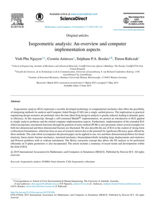
![90 V.P. Nguyen et al. / Mathematics and Computers in Simulation 117 (2015) 89–116
1. Introduction
1.1. Underlying concepts of isogeometric analysis
The predominant technology that is used by Computer Aided Design (CAD) to represent complex geometries
is the Non-Uniform Rational B-spline (NURBS). This allows certain geometries that can only be approximated by
polynomial functions to be represented exactly. Examples of this include conic sections and objects such as cylinders,
spheres, etc. which are essential in design. There is a vast array of literature focused on NURBS (e.g. [96,104]) and as a
result of several decades of research, many efficient computer algorithms exist for their fast evaluation and refinement.
The key concept outlined by Hughes et al. [55] was to employ NURBS not only as a geometry discretization
technology, but also as a discretization tool for analysis, attributing such methods to the field of ‘Isogeometric
Analysis’ (IGA). Since this seminal paper, a monograph dedicated entirely to IGA has been published [27] and
applications can now be found in several fields including structural mechanics, solid mechanics, fluid mechanics
and contact mechanics.
We give in this section an overview of some of these recent developments while outlining the benefits and present
shortcomings of IGA. It should be emphasized that the idea of using CAD technologies in finite elements (FEs) dates
back at least to [65,64] where B-splines were used as shape functions in Finite Element Method (FEM). In addition,
similar methods which adopt subdivision surfaces have been used to model shells [24]. We also review some of the
recent attempts at simplifying the CAD–FEA (FEA stands for Finite Element Analysis) integration by separating
boundary and domain discretizations.
1.2. Applications
In contact formulations using conventional geometry discretizations, the presence of faceted surfaces can lead to
jumps and oscillations in traction responses unless very fine meshes are used. The benefits of using NURBS over
such an approach are evident, since smooth contact surfaces are obtained, leading to more physically accurate contact
stresses. Recent work in this area includes [137,61,138,74,80,136].
IGA has also shown advantages over traditional approaches in the context of optimization problems, [145,77,99,98]
where the tight coupling with CAD models offers an extremely attractive approach for industrial applications. An-
other attractive class of methods include those that require only a boundary discretization, creating a truly direct
coupling with CAD. Isogeometric boundary element methods for elastostatic analysis were presented in [127,118],
demonstrating that mesh generation can be completely circumvented by using CAD discretizations for analysis.
Shell and plate problems are another field where IGA has demonstrated compelling benefits over conventional
approaches [13,68,14,11,140,40,16]. The smoothness of the NURBS basis functions allows for a straightforward
construction of plate/shell elements. Particularly for thin shells, rotation-free formulations can be easily constructed
[68,67]. Note that for multi-patch NURBS surfaces, rotation-free IGA elements require special treatment at patch
boundaries where the basis functions are found to be C0 continuous. Furthermore, isogeometric plate/shell elements
exhibit much less pronounced shear-locking compared to standard FE plate/shell elements. Elements with smooth
boundaries such as circular and cylindrical elements were successfully constructed using the IGA concept [75,76].
The smoothness of NURBS basis functions is attractive for analysis of fluids [51,94,7] and for fluid–structure
interaction problems [9,10]. In addition, due to the ease of constructing high order continuous basis functions, IGA
has been used with great success in solving PDEs that incorporate fourth order (or higher) derivatives of the field
variable such as the Hill–Cahnard equation [50], explicit gradient damage models [142] and gradient elasticity [48].
The high order NURBS basis has also found potential applications in the Kohn–Sham equation for electronic structure
modeling of semiconducting materials [79].
NURBS provide advantageous properties for structural vibration problems [28,56,139,147] where k-refinement
(unique to IGA) has been shown to provide more robust and accurate frequency spectra than typical higher-order FE
p-methods. Particularly, the optical branches of frequency spectra, which have been identified as contributors to Gibbs
phenomena in wave propagation problems (and the cause of rapid degradation of higher modes in the p-version of
FEM), are eliminated. However when lumped mass matrices were used, the accuracy is limited to second order for
any basis order. High order isogeometric lumped mass matrices are not yet available. The mathematical properties of
IGA were studied in detail by [46].](data:image/gif;base64,R0lGODlhAQABAIAAAAAAAP///yH5BAEAAAAALAAAAAABAAEAAAIBRAA7)