1. www.moldclamps.net info@moldclamps.net 0086-17322110281
DGMF Mold Clamps Co., Ltd
mingfeng425@gmail.com
Please browse our website or contact us for more articles, thank you.
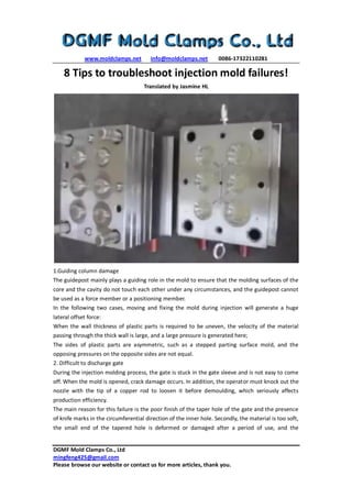
8 Tips to troubleshoot injection mold failures!
Translated by Jasmine HL
1.Guiding column damage
The guidepost mainly plays a guiding role in the mold to ensure that the molding surfaces of the
core and the cavity do not touch each other under any circumstances, and the guidepost cannot
be used as a force member or a positioning member.
In the following two cases, moving and fixing the mold during injection will generate a huge
lateral offset force:
When the wall thickness of plastic parts is required to be uneven, the velocity of the material
passing through the thick wall is large, and a large pressure is generated here;
The sides of plastic parts are asymmetric, such as a stepped parting surface mold, and the
opposing pressures on the opposite sides are not equal.
2. Difficult to discharge gate
During the injection molding process, the gate is stuck in the gate sleeve and is not easy to come
off. When the mold is opened, crack damage occurs. In addition, the operator must knock out the
nozzle with the tip of a copper rod to loosen it before demoulding, which seriously affects
production efficiency.
The main reason for this failure is the poor finish of the taper hole of the gate and the presence
of knife marks in the circumferential direction of the inner hole. Secondly, the material is too soft,
the small end of the tapered hole is deformed or damaged after a period of use, and the
2. www.moldclamps.net info@moldclamps.net 0086-17322110281
DGMF Mold Clamps Co., Ltd
mingfeng425@gmail.com
Please browse our website or contact us for more articles, thank you.
spherical curvature of the nozzle is too small, which causes the gate material to produce a rivet
head here. The taper hole of the gate sleeve is difficult to process. Standard parts should be used
as much as possible. If you need to process it yourself, you should also make or buy a special
reamer. Taper holes need to be ground to Ra0.4 or less. In addition, a gate pulling rod or a gate
ejection mechanism must be provided.
3. Movement and fixed mold offset
For large molds, due to the different filling rates in each direction, and due to the weight of the
mold during mold loading, shifting of the movable and fixed molds occurs. In these cases, the
lateral offset force will be added to the guidepost during the injection. The surface of the guide
post will be fuzzed and damaged when the mold is opened. In severe cases, the guidepost will be
bent or cut, and the mold cannot even be opened.
In order to solve the above problems, a high-strength positioning key is added on each side of the
mold parting surface, and the most convenient and effective is to use a cylindrical key. The
verticality of the guide hole and the parting surface is very important. During processing, the
moving is used. After the fixed mold alignment position is clamped, the boring is completed once
on the boring machine. This can ensure the concentricity of the moving and fixed mold holes and
minimize the verticality error. In addition, the heat treatment hardness of the guide post and
guide sleeve must meet the design requirements.
4. Moving template bending
When the mold is injected, the molten plastic in the mold cavity generates huge backpressure,
which is generally 600 ~ 1000 kg / cm2. The mold maker sometimes does not pay attention to
this problem, often changes the original design size, or replaces the movable template with a
low-strength steel plate. In a mold that uses ejector pins, the template has a large bending span
during injection, which causes the template to bend down during injection.
Therefore, the moving formwork must be made of high-quality steel, and it must have sufficient
thickness. Low-strength steel plates such as A3 must not be used. When necessary, support
columns or blocks should be set under the moving formwork to reduce the thickness of the
formwork and improve the carrying capacity.
5. The jack is bent, broken or missing
The quality of the self-made ejector is good, which means that the processing cost is too high.
Nowadays, standard parts are usually used, and the quality is average. If the gap between the
ejector pin and the hole is too large, material leakage will occur, but if the clearance is too small,
the ejector pin will swell due to the rise of the mold temperature during the injection. What is
more dangerous is that sometimes the ejector pin is ejected at a normal distance and breaks. As
a result, the exposed ejector pin cannot be reset when the next mold is closed, and the concave
mold is damaged.
In order to solve this problem, the ejector rod was reground, and a fitting section of 10-15 mm
was retained at the front end of the ejector rod, and the middle part was milled 0.2 mm smaller.
After the assembly of all ejectors, the fit clearance must be strictly checked, generally within 0.05
~ 0.08 mm, to ensure that the entire ejection mechanism can move forward and backward freely.
3. www.moldclamps.net info@moldclamps.net 0086-17322110281
DGMF Mold Clamps Co., Ltd
mingfeng425@gmail.com
Please browse our website or contact us for more articles, thank you.
6. Poor cooling or water leakage
The cooling effect of the mold directly affects the quality and production efficiency of the product,
such as defects such as poor cooling, large shrinkage of the product, or uneven shrinkage and
deformation of the warped surface. On the other hand, the mold is overheated in whole or in
part, making the mold unable to be molded normally and stopping production. In severe cases,
the movable parts such as the ejector pin are thermally expanded and stuck and damaged.
The design and processing of the cooling system are determined by the shape of the product. Do
not omit this system because of the complex mold structure or difficult processing, especially the
large and medium molds that must fully consider the cooling problem.
7. Guide groove length is too small
Some molds are limited by the area of the template and the length of the guide groove is too
small. The slider is exposed outside the guide groove after the core pulling operation is
completed. This makes it easy to cause the slider to tilt during the core pulling stage and the
initial stage of mold clamping reset, especially in the mold clamping. When the slider is not reset
smoothly, the slider is damaged or even damaged by bending. According to experience, after the
slider completes the core pulling action, the length remaining in the slide groove should not be
less than 2/3 of the total length of the guide groove.
8. The fixed distance tensioning mechanism fails
Fixed distance tensioning mechanisms such as pendulum hooks and buckles are generally used in
fixed core pulling or some secondary demoulding molds. Because this type of mechanism is
arranged in pairs on both sides of the mold, their actions must be synchronized, that is, The mold
is buckled at the same time, and the mold is released to a certain position and unhooked at the
same time.
Once the synchronization is lost, the template of the drawn mold will inevitably be skewed and
damaged. The parts of these mechanisms must have high rigidity and abrasion resistance. It is
also difficult to adjust, and the life of the mechanism is short. Avoid using it as much as possible
and use other mechanisms. In the case of a relatively small core-pulling force, a spring can be
used to push the fixed mold. In the case of a relatively large core-pulling force, the core can slide
when the movable mold is retracted, and the structure of the core-pulling is completed after the
core-pulling action is completed. The hydraulic cylinder can be used for core pulling on the mold.
The oblique pin slider core pulling mechanism is damaged.
The most common problems with this mechanism are inadequate processing and the use of
small materials. There are two main problems:
The angle of inclination pin A is large;
The advantage is that a large core-pulling distance can be produced in a short mold opening
stroke.
However, if the inclination angle A is too large, when the pulling force F is a certain value, the
bending force P = F / COSA that the oblique pin receives during the core drawing process is larger,
and the oblique pin deformation and oblique hole wear are likely to occur.
At the same time, the oblique pin produces an upward thrust N = FTGA on the slider, which
4. www.moldclamps.net info@moldclamps.net 0086-17322110281
DGMF Mold Clamps Co., Ltd
mingfeng425@gmail.com
Please browse our website or contact us for more articles, thank you.
increases the positive pressure of the slider on the guide surface in the guide groove, thereby
increasing the frictional resistance when the slider slides. Easy to cause sliding irregularities,
guide groove wear. According to experience, the inclination angle A should not be greater than
25 °.