Water Industry Process Automation & Control Monthly - April 2024
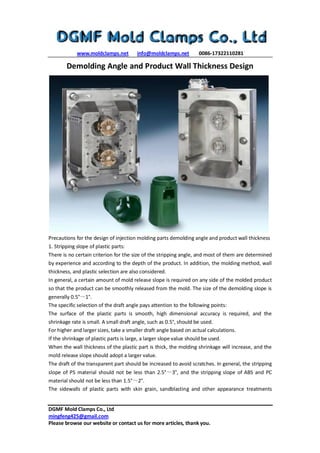
Demolding angle and product wall thickness design
1. www.moldclamps.net info@moldclamps.net 0086-17322110281
DGMF Mold Clamps Co., Ltd
mingfeng425@gmail.com
Please browse our website or contact us for more articles, thank you.
Demolding Angle and Product Wall Thickness Design
Precautions for the design of injection molding parts demolding angle and product wall thickness
1. Stripping slope of plastic parts:
There is no certain criterion for the size of the stripping angle, and most of them are determined
by experience and according to the depth of the product. In addition, the molding method, wall
thickness, and plastic selection are also considered.
In general, a certain amount of mold release slope is required on any side of the molded product
so that the product can be smoothly released from the mold. The size of the demolding slope is
generally 0.5°~1°.
The specific selection of the draft angle pays attention to the following points:
The surface of the plastic parts is smooth, high dimensional accuracy is required, and the
shrinkage rate is small. A small draft angle, such as 0.5°, should be used.
For higher and larger sizes, take a smaller draft angle based on actual calculations.
If the shrinkage of plastic parts is large, a larger slope value should be used.
When the wall thickness of the plastic part is thick, the molding shrinkage will increase, and the
mold release slope should adopt a larger value.
The draft of the transparent part should be increased to avoid scratches. In general, the stripping
slope of PS material should not be less than 2.5°~3°, and the stripping slope of ABS and PC
material should not be less than 1.5°~2°.
The sidewalls of plastic parts with skin grain, sandblasting and other appearance treatments
2. www.moldclamps.net info@moldclamps.net 0086-17322110281
DGMF Mold Clamps Co., Ltd
mingfeng425@gmail.com
Please browse our website or contact us for more articles, thank you.
should be taken from 2°to 5°according to the specific situation, depending on the specific skin
grain depth. The deeper the dermatoglyphics depth, the greater the release slope.
When the structure is designed to be inserted in pairs, the slope of the insertion surface is
generally 1°to 3°.
The direction of the slope is taken. In general, the inner hole is based on the small end and
conforms to the pattern. The slope is obtained from the enlarged direction. The shape is based
on the large end and conforms to the pattern. The slope is obtained from the reduced direction.
In general, the draft angle is not included in the tolerance of plastic parts.
The stripping slope of the shell surface is greater than or equal to 3°. Except for the shell surface,
the demolding slope of the remaining features of the shell is 1°as the standard demolding slope.
In particular, it can also be taken according to the following principles: the draft of the ribs below
3mm is 0.5°, the draft of 3~5mm is 1°, and the rest is 1.5°; the draft of the cavity below 3mm is 1.
The degree is 0.5°, 3~5mm is 1°, and the rest is 1.5°.
2. Determining the wall thickness of plastic parts and processing the wall thickness
It is important to reasonably determine the wall thickness of plastic parts. The wall thickness of
plastic parts is first determined by the use requirements of the plastic parts: including the
strength, quality cost, electrical performance, dimensional stability, and assembly of the parts.
Generally, the wall thickness has empirical values, which can be determined by reference to
similar.
The points of attention are as follows:
The wall thickness of the plastic parts should be as uniform as possible, to avoid too thin, too
thick and sudden changes in wall thickness, if the plastic parts require wall thickness changes,
gradient or arc transition should be used, otherwise, the plastic parts will be deformed and
affected due to uneven shrinkage Molding process problems such as the strength of plastic parts
and affecting the fluidity during the injection. The thickness difference should be controlled
within 25% of the basic wall thickness as much as possible. The minimum wall thickness of the
entire component should not be less than 0.4mm, and the backside is not a Class A appearance
surface, and the area must not be greater than 100mm².
The wall thickness of plastic parts is generally in the range of 1 ~ 5mm. The most commonly used
value is 2 ~ 3mm.
Try not to design the ribs and screw columns too thick. It is generally recommended to take half
of the wall thickness of the body to be safe, otherwise, it will easily cause appearance problems
such as microcosm.
Try not to design the part as a separate flat plate, the size is very small, otherwise, the
deformation will cause the part to be uneven.