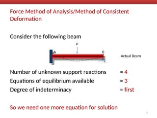
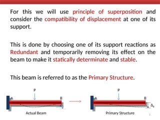
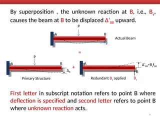
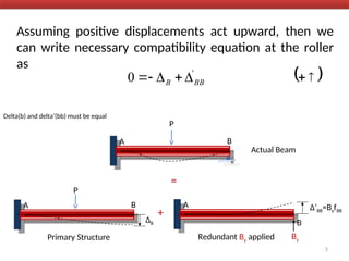
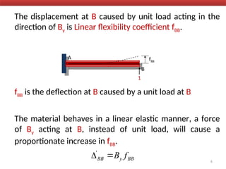
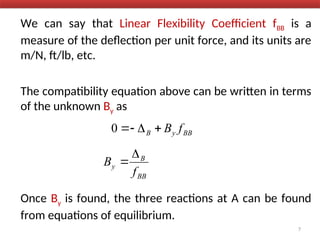
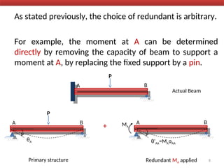
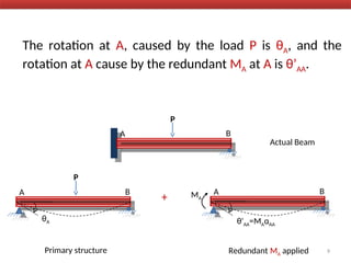
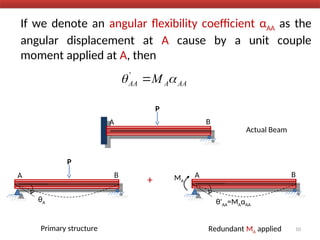
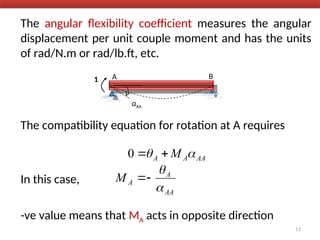
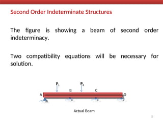
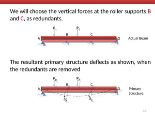
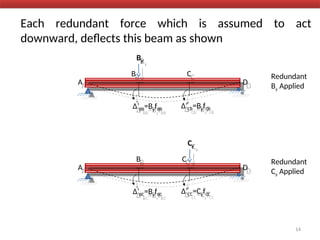
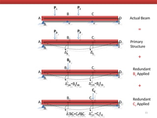
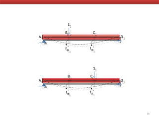
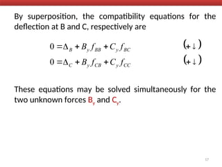
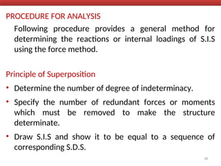
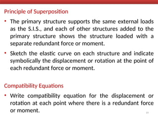
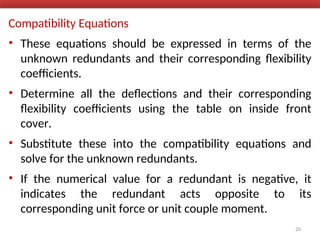
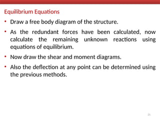
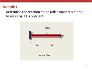
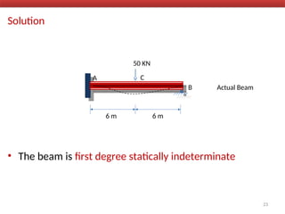
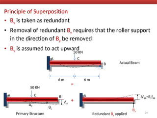
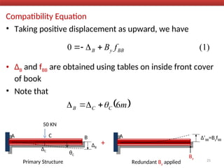
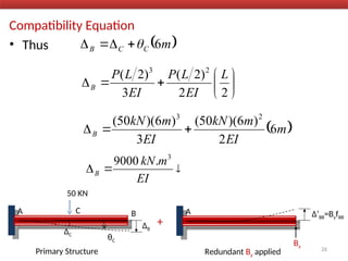
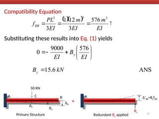
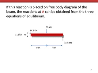
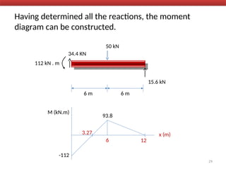
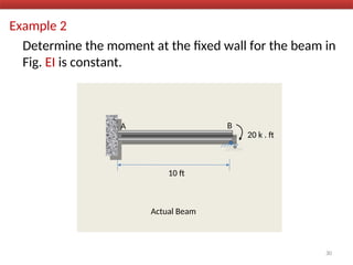
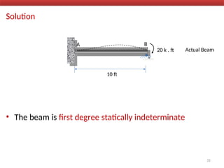
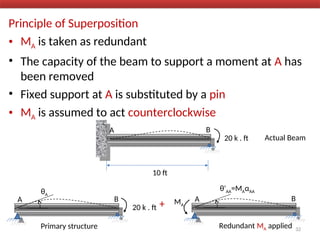
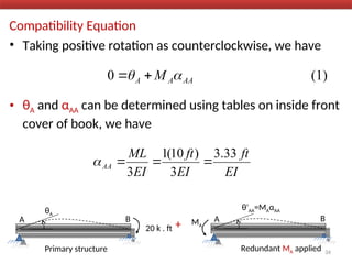
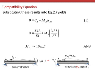
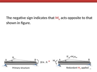
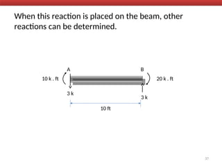
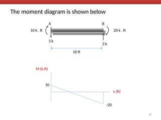
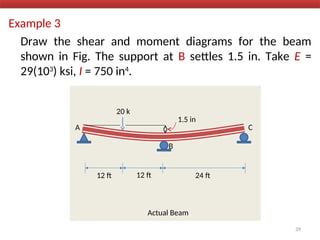
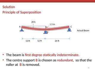
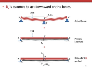
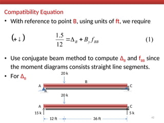
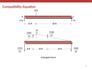
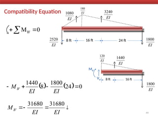
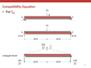
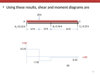
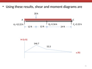
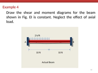
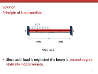
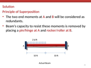
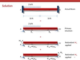
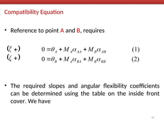
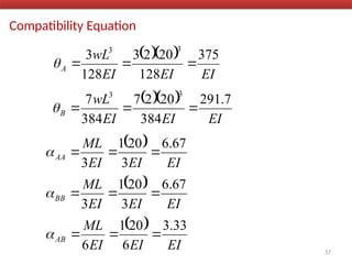
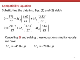
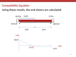
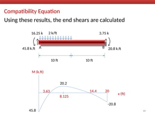
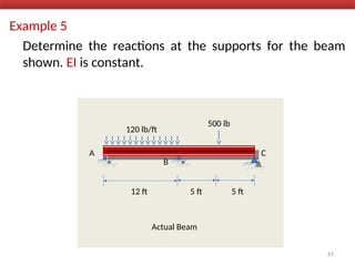
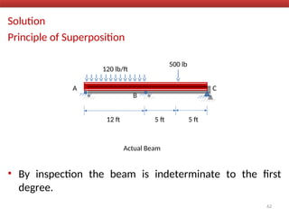
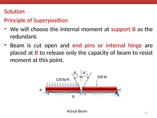
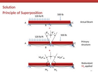
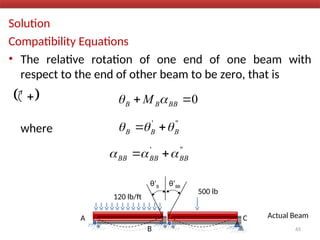
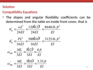
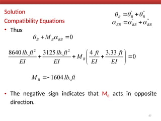
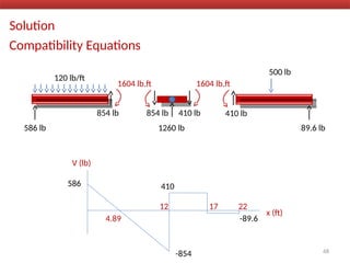
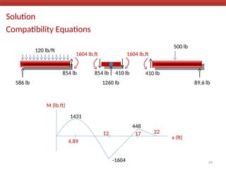
Method of Consistent
Deformation
Structural Analysis
By
R. C. Hibbeler
Force Method of Analysis/Method of Consistent
Deformation
Consider the following beam
Number of unknown support reactions = 4
Equations of equilibrium available = 3
Degree of indeterminacy = first
So we need one more equation for solution
A B
P
Actual Beam
2
For this we will use principle of superposition and
consider the compatibility of displacement at one of its
support.
This is done by choosing one of its support reactions as
Redundant and temporarily removing its effect on the
beam to make it statically determinate and stable.
This beam is referred to as the Primary Structure.
3
A B
P
Actual Beam
A B
P
Primary Structure
ΔB
By superposition , the unknown reaction at B, i.e., By,
causes the beam at B to be displaced Δ’BB upward.
First letter in subscript notation refers to point B where
deflection is specified and second letter refers to point B
where unknown reaction acts.
A B
P
Actual Beam
A B
P
Primary Structure
ΔB
=
A Δ’BB=ByfBB
Redundant By applied By
4
+
B
Assuming positive displacements act upward, then we
can write necessary compatibility equation at the roller
as
Delta(b) and delta’(bb) must be equal
A B
P
Actual Beam
A B
P
Primary Structure
ΔB
=
A Δ’BB=ByfBB
Redundant By applied By
5
+
B
 







0 '
BB
B
The displacement at B caused by unit load acting in the
direction of By is Linear flexibility coefficient fBB.
fBB is the deflection at B caused by a unit load at B
The material behaves in a linear elastic manner, a force
of By acting at B, instead of unit load, will cause a
proportionate increase in fBB.
A fBB
1
6
B
BB
y
BB f
B

'
We can say that Linear Flexibility Coefficient fBB is a
measure of the deflection per unit force, and its units are
m/N, ft/lb, etc.
The compatibility equation above can be written in terms
of the unknown By as
Once By is found, the three reactions at A can be found
from equations of equilibrium.
7
BB
y
B f
B




0
BB
B
y
f
B


As stated previously, the choice of redundant is arbitrary.
For example, the moment at A can be determined
directly by removing the capacity of beam to support a
moment at A, by replacing the fixed support by a pin.
8
A B
Actual Beam
A B
θA
Primary structure
+
A B
θ'AA=MAαAA
Redundant MA applied
MA
P
P
The rotation at A, caused by the load P is θA, and the
rotation at A cause by the redundant MA at A is θ’AA.
9
A B
Actual Beam
A B
θA
Primary structure
+
A B
θ'AA=MAαAA
Redundant MA applied
MA
P
P
If we denote an angular flexibility coefficient αAA as the
angular displacement at A cause by a unit couple
moment applied at A, then
10
A B
Actual Beam
A B
θA
Primary structure
+
A B
θ'AA=MAαAA
Redundant MA applied
MA
P
P
AA
A
AA M 
 
'
The angular flexibility coefficient measures the angular
displacement per unit couple moment and has the units
of rad/N.m or rad/lb.ft, etc.
The compatibility equation for rotation at A requires
In this case,
-ve value means that MA acts in opposite direction
11
A B
αAA
1
AA
A
A M 
 

0
AA
A
A
M




Second Order Indeterminate Structures
The figure is showing a beam of second order
indeterminacy.
Two compatibility equations will be necessary for
solution.
12
A
B C
D
Actual Beam
P1
P2
We will choose the vertical forces at the roller supports B
and C, as redundants.
The resultant primary structure deflects as shown, when
the redundants are removed
13
A
B C
D Actual Beam
P1
P2
A
B C
D Primary
Structure
P1
P2
ΔB
ΔC
Each redundant force which is assumed to act
downward, deflects this beam as shown
14
A
B C
D
By
Δ’BB=ByfBB
Δ’CB=ByfCB
Redundant
By Applied
A
B C
D
Cy
Δ’BC=ByfBC
Δ’CC=CyfCC
Redundant
Cy Applied
15
A
B C
D
By
Δ’BB=ByfBB
Δ’CB=ByfCB
Redundant
By Applied
A
B C
D
Cy
Δ’BC=CyfBC Δ’CC=CyfCC
Redundant
Cy Applied
A
B C
D Primary
Structure
P1
P2
ΔB ΔC
A
B C
D Actual Beam
P1
P2
+
+
=
16
A
B C
D
1
fBB
fCB
A
B C
D
1
fBC
fCC
By superposition, the compatibility equations for the
deflection at B and C, respectively are
These equations may be solved simultaneously for the
two unknown forces By and Cy.
17
 
 












0
0
CC
y
CB
y
C
BC
y
BB
y
B
f
C
f
B
f
C
f
B
PROCEDURE FOR ANALYSIS
Following procedure provides a general method for
determining the reactions or internal loadings of S.I.S
using the force method.
Principle of Superposition
• Determine the number of degree of indeterminacy.
• Specify the number of redundant forces or moments
which must be removed to make the structure
determinate.
• Draw S.I.S and show it to be equal to a sequence of
corresponding S.D.S.
18
Principle of Superposition
• The primary structure supports the same external loads
as the S.I.S., and each of other structures added to the
primary structure shows the structure loaded with a
separate redundant force or moment.
• Sketch the elastic curve on each structure and indicate
symbolically the displacement or rotation at the point of
each redundant force or moment.
Compatibility Equations
• Write compatibility equation for the displacement or
rotation at each point where there is a redundant force
or moment. 19
Compatibility Equations
• These equations should be expressed in terms of the
unknown redundants and their corresponding flexibility
coefficients.
• Determine all the deflections and their corresponding
flexibility coefficients using the table on inside front
cover.
• Substitute these into the compatibility equations and
solve for the unknown redundants.
• If the numerical value for a redundant is negative, it
indicates the redundant acts opposite to its
corresponding unit force or unit couple moment.
20
Equilibrium Equations
• Draw a free body diagram of the structure.
• As the redundant forces have been calculated, now
calculate the remaining unknown reactions using
equations of equilibrium.
• Now draw the shear and moment diagrams.
• Also the deflection at any point can be determined using
the previous methods.
21
Example 1
Determine the reaction at the roller support B of the
beam in Fig. EI is constant.
A
B
C
50 KN
6 m 6 m
Actual Beam
22
Solution
• The beam is first degree statically indeterminate
A
B
C
50 KN
6 m 6 m
Actual Beam
23
Principle of Superposition
• By is taken as redundant
• Removal of redundant By requires that the roller support
in the direction of By be removed
• By is assumed to act upward
A
B
C
50 KN
6 m 6 m
Actual Beam
=
A B
C
50 KN
ΔB
θC
ΔC
Primary Structure
+
A Δ’BB=ByfBB
Redundant By applied
By
24
Compatibility Equation
• Taking positive displacement as upward, we have
• ΔB and fBB are obtained using tables on inside front cover
of book
• Note that
A B
C
50 KN
ΔB
θC
ΔC
Primary Structure
+
A Δ’BB=ByfBB
Redundant By applied
By
(1)
0 BB
y
B f
B




 
m
C
C
B 6





25
Compatibility Equation
• Thus
A B
C
50 KN
ΔB
θC
ΔC
Primary Structure
+
A Δ’BB=ByfBB
Redundant By applied
By
 
m
C
C
B 6














2
2
)
2
(
3
)
2
( 2
3
L
EI
L
P
EI
L
P
B
 
m
EI
m
kN
EI
m
kN
B 6
2
)
6
)(
50
(
3
)
6
)(
50
( 2
3






EI
m
kN
B
3
.
9000
26
Compatibility Equation
Substituting these results into Eq. (1) yields
A B
C
50 KN
ΔB
θC
ΔC
Primary Structure
+
A Δ’BB=ByfBB
Redundant By applied
By
   



EI
m
EI
m
EI
PL
fBB
3
3
3
576
3
12
1
3









EI
B
EI
y
576
9000
0
ANS
6
.
15 kN
By 
27
If this reaction is placed on free body diagram of the
beam, the reactions at A can be obtained from the three
equations of equilibrium.
50 kN
6 m 6 m
15.6 kN
34.4 KN
112 kN . m
28
Having determined all the reactions, the moment
diagram can be constructed.
29
50 kN
6 m 6 m
15.6 kN
34.4 KN
112 kN . m
-112
3.27
6 12
x (m)
M (kN.m)
93.8
Example 2
Determine the moment at the fixed wall for the beam in
Fig. EI is constant.
A B
10 ft
Actual Beam
30
20 k . ft
Solution
• The beam is first degree statically indeterminate
A B
10 ft
Actual Beam
31
20 k . ft
Principle of Superposition
• MA is taken as redundant
• The capacity of the beam to support a moment at A has
been removed
• Fixed support at A is substituted by a pin
• MA is assumed to act counterclockwise
A B
10 ft
Actual Beam
32
20 k . ft
A B
20 k . ft
θA
Primary structure
+
A B
θ'AA=MAαAA
Redundant MA applied
MA
Compatibility Equation
• Taking positive rotation as counterclockwise, we have
• θA and αAA can be determined using tables on inside front
cover of book, we have
(1)
0 AA
A
A M 
 

33
EI
ft
k
EI
ft
ft
k
EI
ML
A
2
.
3
.
33
6
)
10
(
.
20
6




A B
20 k . ft
θA
Primary structure
+
A B
θ'AA=MAαAA
Redundant MA applied
MA
Compatibility Equation
• Taking positive rotation as counterclockwise, we have
• θA and αAA can be determined using tables on inside front
cover of book, we have
(1)
0 AA
A
A M 
 

34
EI
ft
EI
ft
EI
ML
AA
.33
3
3
)
10
(
1
3




A B
20 k . ft
θA
Primary structure
+
A B
θ'AA=MAαAA
Redundant MA applied
MA
Compatibility Equation
Substituting these results into Eq.(1) yields
(1)
0 AA
A
A M 
 

35
ANS
.
10
33
.
3
3
.
33
0
ft
k
M
EI
M
EI
A
A










A B
20 k . ft
θA
Primary structure
+
A B
θ'AA=MAαAA
Redundant MA applied
MA
The negative sign indicates that MA acts opposite to that
shown in figure.
36
A B
20 k . ft
θA
Primary structure
+
A B
θ'AA=MAαAA
Redundant MA applied
MA
When this reaction is placed on the beam, other
reactions can be determined.
37
10 ft
3 k
A
10 k . ft
3 k
B
20 k . ft
The moment diagram is shown below
38
10 ft
3 k
A
10 k . ft
3 k
B
20 k . ft
x (ft)
M (k.ft)
-20
10
Example 3
Draw the shear and moment diagrams for the beam
shown in Fig. The support at B settles 1.5 in. Take E =
29(103
) ksi, I = 750 in4
.
A C
20 k
12 ft 24 ft
Actual Beam
39
B
1.5 in
12 ft
Solution
Principle of Superposition
• The beam is first degree statically indeterminate.
• The centre support B is chosen as redundant, so that the
roller at B is removed.
40
A C
20 k
12 ft 24 ft
Actual Beam
B
1.5 in
12 ft
• By is assumed to act downward on the beam.
41
A C
+
A C
20 k
Actual Beam
B
1.5 in
=
B
ΔB
Primary
Structure
20 k
A C
B
Δ’BB=ByfBB
By
Redundant By
applied
Compatibility Equation
• With reference to point B, using units of ft, we require
• Use conjugate beam method to compute ΔB and fBB since
the moment diagrams consists straight line segments.
• For ΔB
  (1)
12
5
.
1
BB
y
B f
B





42
A C
B
20 k
A C
20 k
12 ft 36 ft
15 k 5 k
Compatibility Equation
43
A C
20 k
12 ft 36 ft
15 k 5 k
8 ft 24 ft
EI
2520
EI
1800
EI
1080
EI
3240
EI
180
16 ft
conjugate beam
Compatibility Equation
44
8 ft 24 ft
EI
2520
EI
1800
EI
1080
EI
3240
EI
180
16 ft
EI
1800
EI
1440
8 ft 16 ft
VB’
MB’
EI
120
0
MB' 

    0
24
1800
8
1440
' 



EI
EI
MB




EI
EI
MB
31680
31680
'
Compatibility Equation
• For fBB
45
A C
B
1 k
A C
24 ft 24 ft
0.5 k 0.5 k
1 k
24 ft 24 ft
conjugate beam
EI
144
EI
144
EI
288
EI
12
Compatibility Equation
• For fBB
46
24 ft 24 ft
conjugate beam
EI
144
EI
144
EI
288
EI
12
EI
144
EI
144
24 ft
vB’
mB’
EI
12
8 ft
0
MB' 

    0
24
144
8
144
' 



EI
EI
mB




EI
EI
mB
2304
2304
'
Compatibility Equation
• Substituting these results into eq. (1), we have
• Expressing the units of E and I in terms of k and ft, we
have
  (1)
12
5
.
1
BB
y
B f
B





47








EI
B
EI
.
y
2304
31680
12
5
1
   
 
   
 
 
 
2304
31680
12
750
12
10
29
12
5
1 4
4
4
4
2
2
2
2
3
y
B
in
ft
in
ft
in
in
k
ft
.








Equilibrium Equations
• The negative sign indicates that By acts upward on the
beam.
48
k
By 56
.
5


A C
20 k
12 ft 24 ft
Ay
Cy
By=5.56 k
12 ft
Equilibrium Equations
49
A C
20 k
12 ft 24 ft
Ay=12.22 k Cy=2.22 k
By=5.56 k
12 ft
0
MA 
       0
48
24
56
.
5
12
20 


 y
C
k
Cy 22
.
2

0
Fy 

  0
22
.
2
56
.
5
20 



y
A
k
Ay 22
.
12

• Using these results, shear and moment diagrams are
50
x (ft)
V (k)
-20
12.22
-7.78
-2.22
A C
20 k
12 ft 24 ft
Ay=12.22 k Cy=2.22 k
By=5.56 k
12 ft
• Using these results, shear and moment diagrams are
51
x (ft)
M (k.ft)
A C
20 k
12 ft 24 ft
Ay=12.22 k Cy=2.22 k
By=5.56 k
12 ft
146.7
53.3
Example 4
Draw the shear and moment diagrams for the beam
shown in Fig. EI is constant. Neglect the effect of axial
load.
52
A B
2 k/ft
10 ft 10 ft
Actual Beam
Solution
Principle of Superposition
• Since axial load is neglected the beam is second degree
statically indeterminate.
53
A B
2 k/ft
10 ft 10 ft
Actual Beam
Solution
Principle of Superposition
• The two end moments at A and B will be considered as
redundants.
• Beam’s capacity to resist these moments is removed by
placing a pin/hinge at A and rocker/roller at B.
54
A B
2 k/ft
10 ft 10 ft
Actual Beam
Solution
55
A B
2 k/ft
10 ft 10 ft
Actual Beam
=
A B
2 k/ft
Primary
structure
+
θA θB
A
B Redundant MA
applied
MA
θ'AA=MAαAA θ‘BA=MAαBA
+
A B
Redundant MB
applied
MB
θ'AB=MBαAB θ‘BB=MBαBB
Compatibility Equation
• Reference to point A and B, requires
• The required slopes and angular flexibility coefficients
can be determined using the table on the inside front
cover. We have
 

(2)
0
(1)
0
BB
B
BA
A
B
AB
B
AA
A
A
M
M
M
M












56
 

Compatibility Equation
  
EI
EI
EI
wL
A
375
128
20
2
3
128
3
3
3




57
  
EI
EI
EI
wL
B
7
.
291
384
20
2
7
384
7
3
3




 
EI
EI
EI
ML
AA
67
.
6
3
20
1
3




 
EI
EI
EI
ML
BB
67
.
6
3
20
1
3




 
EI
EI
EI
ML
AB
33
.
3
6
20
1
6




Compatibility Equation
Substituting the data into Eqs. (1) and (2) yields
Cancelling EI and solving these equations simultaneously,
we have
58






























EI
M
EI
M
EI
EI
M
EI
M
EI
B
A
B
A
67
.
6
33
.
3
7
.
291
0
33
.
3
67
.
6
375
0
ft
k
M
ft
k
M B
A .
8
.
20
.
8
.
45 



Compatibility Equation
Using these results, the end shears are calculated
59
A B
2 k/ft
10 ft 10 ft
16.25 k 3.75 k
45.8 k.ft 20.8 k.ft
x (ft)
V (k)
16.25
-3.75
8.125
Compatibility Equation
Using these results, the end shears are calculated
60
A B
2 k/ft
10 ft 10 ft
16.25 k 3.75 k
45.8 k.ft 20.8 k.ft
x (ft)
M (k.ft)
45.8
20.2
-20.8
8.125
3.63 14.4 20
Example 5
Determine the reactions at the supports for the beam
shown. EI is constant.
61
A C
120 lb/ft
12 ft 5 ft
Actual Beam
500 lb
5 ft
B
Solution
Principle of Superposition
• By inspection the beam is indeterminate to the first
degree.
62
A C
120 lb/ft
12 ft 5 ft
Actual Beam
500 lb
5 ft
B
Solution
Principle of Superposition
• We will choose the internal moment at support B as the
redundant.
• Beam is cut open and end pins or internal hinge are
placed at B to release only the capacity of beam to resist
moment at this point.
63
A C
120 lb/ft
Actual Beam
500 lb
B
θ‘B θ‘’B
Solution
Principle of Superposition
64
A C
120 lb/ft
Primary
structure
500 lb
B
θ‘B θ‘’B
A C
120 lb/ft
Actual Beam
500 lb
B
=
+
Redundant
MB applied
MBα‘BB MBα’‘BB
MB MB
Solution
Compatibility Equations
• The relative rotation of one end of one beam with
respect to the end of other beam to be zero, that is
where
65
A C
120 lb/ft
Actual Beam
500 lb
B
θ‘B θ‘BB
0

 BB
B
B M 

 

'
'
'
B
B
B 

 

'
'
'
BB
BB
BB 

 

Solution
Compatibility Equations
• The slopes and angular flexibility coefficients can be
determined from the table on inside front cover, that is
66
 
EI
ft
lb
EI
EI
wL
θ'
B
2
3
3
.
8640
24
12
120
24



 
EI
ft
lb
EI
EI
PL
θ '
B
2
2
2
' .
125
3
16
10
500
16



 
EI
ft
EI
EI
ML
'
BB
4
3
12
1
3




 
EI
ft
EI
EI
ML
'
BB
33
.
3
3
10
1
3
'




Solution
Compatibility Equations
• Thus
• The negative sign indicates that MB acts in opposite
direction.
67
0

 BB
B
B M 

'
'
'
B
B
B 

 

'
'
'
BB
BB
BB 

 

0
33
.
3
4
.
3125
.
8640 2
2










EI
ft
EI
ft
M
EI
ft
lb
EI
ft
lb
B
ft
lb
MB .
1604


Solution
Compatibility Equations
68
120 lb/ft
500 lb
586 lb
854 lb 854 lb
1260 lb
410 lb 410 lb
89.6 lb
1604 lb.ft
1604 lb.ft
x (ft)
V (lb)
586
-854
410
-89.6
4.89
12 17 22
Solution
Compatibility Equations
69
120 lb/ft
500 lb
586 lb
854 lb 854 lb
1260 lb
410 lb 410 lb
89.6 lb
1604 lb.ft
1604 lb.ft
x (ft)
M (lb.ft)
1431
4.89
12 17 22
-1604
448

Lecture 2 METHOD OF CONSISTENT DEFORMATION Beams.ppt

  • 1.
  • 2.
    Force Method ofAnalysis/Method of Consistent Deformation Consider the following beam Number of unknown support reactions = 4 Equations of equilibrium available = 3 Degree of indeterminacy = first So we need one more equation for solution A B P Actual Beam 2
  • 3.
    For this wewill use principle of superposition and consider the compatibility of displacement at one of its support. This is done by choosing one of its support reactions as Redundant and temporarily removing its effect on the beam to make it statically determinate and stable. This beam is referred to as the Primary Structure. 3 A B P Actual Beam A B P Primary Structure ΔB
  • 4.
    By superposition ,the unknown reaction at B, i.e., By, causes the beam at B to be displaced Δ’BB upward. First letter in subscript notation refers to point B where deflection is specified and second letter refers to point B where unknown reaction acts. A B P Actual Beam A B P Primary Structure ΔB = A Δ’BB=ByfBB Redundant By applied By 4 + B
  • 5.
    Assuming positive displacementsact upward, then we can write necessary compatibility equation at the roller as Delta(b) and delta’(bb) must be equal A B P Actual Beam A B P Primary Structure ΔB = A Δ’BB=ByfBB Redundant By applied By 5 + B          0 ' BB B
  • 6.
    The displacement atB caused by unit load acting in the direction of By is Linear flexibility coefficient fBB. fBB is the deflection at B caused by a unit load at B The material behaves in a linear elastic manner, a force of By acting at B, instead of unit load, will cause a proportionate increase in fBB. A fBB 1 6 B BB y BB f B  '
  • 7.
    We can saythat Linear Flexibility Coefficient fBB is a measure of the deflection per unit force, and its units are m/N, ft/lb, etc. The compatibility equation above can be written in terms of the unknown By as Once By is found, the three reactions at A can be found from equations of equilibrium. 7 BB y B f B     0 BB B y f B  
  • 8.
    As stated previously,the choice of redundant is arbitrary. For example, the moment at A can be determined directly by removing the capacity of beam to support a moment at A, by replacing the fixed support by a pin. 8 A B Actual Beam A B θA Primary structure + A B θ'AA=MAαAA Redundant MA applied MA P P
  • 9.
    The rotation atA, caused by the load P is θA, and the rotation at A cause by the redundant MA at A is θ’AA. 9 A B Actual Beam A B θA Primary structure + A B θ'AA=MAαAA Redundant MA applied MA P P
  • 10.
    If we denotean angular flexibility coefficient αAA as the angular displacement at A cause by a unit couple moment applied at A, then 10 A B Actual Beam A B θA Primary structure + A B θ'AA=MAαAA Redundant MA applied MA P P AA A AA M    '
  • 11.
    The angular flexibilitycoefficient measures the angular displacement per unit couple moment and has the units of rad/N.m or rad/lb.ft, etc. The compatibility equation for rotation at A requires In this case, -ve value means that MA acts in opposite direction 11 A B αAA 1 AA A A M     0 AA A A M    
  • 12.
    Second Order IndeterminateStructures The figure is showing a beam of second order indeterminacy. Two compatibility equations will be necessary for solution. 12 A B C D Actual Beam P1 P2
  • 13.
    We will choosethe vertical forces at the roller supports B and C, as redundants. The resultant primary structure deflects as shown, when the redundants are removed 13 A B C D Actual Beam P1 P2 A B C D Primary Structure P1 P2 ΔB ΔC
  • 14.
    Each redundant forcewhich is assumed to act downward, deflects this beam as shown 14 A B C D By Δ’BB=ByfBB Δ’CB=ByfCB Redundant By Applied A B C D Cy Δ’BC=ByfBC Δ’CC=CyfCC Redundant Cy Applied
  • 15.
    15 A B C D By Δ’BB=ByfBB Δ’CB=ByfCB Redundant By Applied A BC D Cy Δ’BC=CyfBC Δ’CC=CyfCC Redundant Cy Applied A B C D Primary Structure P1 P2 ΔB ΔC A B C D Actual Beam P1 P2 + + =
  • 16.
  • 17.
    By superposition, thecompatibility equations for the deflection at B and C, respectively are These equations may be solved simultaneously for the two unknown forces By and Cy. 17                 0 0 CC y CB y C BC y BB y B f C f B f C f B
  • 18.
    PROCEDURE FOR ANALYSIS Followingprocedure provides a general method for determining the reactions or internal loadings of S.I.S using the force method. Principle of Superposition • Determine the number of degree of indeterminacy. • Specify the number of redundant forces or moments which must be removed to make the structure determinate. • Draw S.I.S and show it to be equal to a sequence of corresponding S.D.S. 18
  • 19.
    Principle of Superposition •The primary structure supports the same external loads as the S.I.S., and each of other structures added to the primary structure shows the structure loaded with a separate redundant force or moment. • Sketch the elastic curve on each structure and indicate symbolically the displacement or rotation at the point of each redundant force or moment. Compatibility Equations • Write compatibility equation for the displacement or rotation at each point where there is a redundant force or moment. 19
  • 20.
    Compatibility Equations • Theseequations should be expressed in terms of the unknown redundants and their corresponding flexibility coefficients. • Determine all the deflections and their corresponding flexibility coefficients using the table on inside front cover. • Substitute these into the compatibility equations and solve for the unknown redundants. • If the numerical value for a redundant is negative, it indicates the redundant acts opposite to its corresponding unit force or unit couple moment. 20
  • 21.
    Equilibrium Equations • Drawa free body diagram of the structure. • As the redundant forces have been calculated, now calculate the remaining unknown reactions using equations of equilibrium. • Now draw the shear and moment diagrams. • Also the deflection at any point can be determined using the previous methods. 21
  • 22.
    Example 1 Determine thereaction at the roller support B of the beam in Fig. EI is constant. A B C 50 KN 6 m 6 m Actual Beam 22
  • 23.
    Solution • The beamis first degree statically indeterminate A B C 50 KN 6 m 6 m Actual Beam 23
  • 24.
    Principle of Superposition •By is taken as redundant • Removal of redundant By requires that the roller support in the direction of By be removed • By is assumed to act upward A B C 50 KN 6 m 6 m Actual Beam = A B C 50 KN ΔB θC ΔC Primary Structure + A Δ’BB=ByfBB Redundant By applied By 24
  • 25.
    Compatibility Equation • Takingpositive displacement as upward, we have • ΔB and fBB are obtained using tables on inside front cover of book • Note that A B C 50 KN ΔB θC ΔC Primary Structure + A Δ’BB=ByfBB Redundant By applied By (1) 0 BB y B f B       m C C B 6      25
  • 26.
    Compatibility Equation • Thus AB C 50 KN ΔB θC ΔC Primary Structure + A Δ’BB=ByfBB Redundant By applied By   m C C B 6               2 2 ) 2 ( 3 ) 2 ( 2 3 L EI L P EI L P B   m EI m kN EI m kN B 6 2 ) 6 )( 50 ( 3 ) 6 )( 50 ( 2 3       EI m kN B 3 . 9000 26
  • 27.
    Compatibility Equation Substituting theseresults into Eq. (1) yields A B C 50 KN ΔB θC ΔC Primary Structure + A Δ’BB=ByfBB Redundant By applied By        EI m EI m EI PL fBB 3 3 3 576 3 12 1 3          EI B EI y 576 9000 0 ANS 6 . 15 kN By  27
  • 28.
    If this reactionis placed on free body diagram of the beam, the reactions at A can be obtained from the three equations of equilibrium. 50 kN 6 m 6 m 15.6 kN 34.4 KN 112 kN . m 28
  • 29.
    Having determined allthe reactions, the moment diagram can be constructed. 29 50 kN 6 m 6 m 15.6 kN 34.4 KN 112 kN . m -112 3.27 6 12 x (m) M (kN.m) 93.8
  • 30.
    Example 2 Determine themoment at the fixed wall for the beam in Fig. EI is constant. A B 10 ft Actual Beam 30 20 k . ft
  • 31.
    Solution • The beamis first degree statically indeterminate A B 10 ft Actual Beam 31 20 k . ft
  • 32.
    Principle of Superposition •MA is taken as redundant • The capacity of the beam to support a moment at A has been removed • Fixed support at A is substituted by a pin • MA is assumed to act counterclockwise A B 10 ft Actual Beam 32 20 k . ft A B 20 k . ft θA Primary structure + A B θ'AA=MAαAA Redundant MA applied MA
  • 33.
    Compatibility Equation • Takingpositive rotation as counterclockwise, we have • θA and αAA can be determined using tables on inside front cover of book, we have (1) 0 AA A A M     33 EI ft k EI ft ft k EI ML A 2 . 3 . 33 6 ) 10 ( . 20 6     A B 20 k . ft θA Primary structure + A B θ'AA=MAαAA Redundant MA applied MA
  • 34.
    Compatibility Equation • Takingpositive rotation as counterclockwise, we have • θA and αAA can be determined using tables on inside front cover of book, we have (1) 0 AA A A M     34 EI ft EI ft EI ML AA .33 3 3 ) 10 ( 1 3     A B 20 k . ft θA Primary structure + A B θ'AA=MAαAA Redundant MA applied MA
  • 35.
    Compatibility Equation Substituting theseresults into Eq.(1) yields (1) 0 AA A A M     35 ANS . 10 33 . 3 3 . 33 0 ft k M EI M EI A A           A B 20 k . ft θA Primary structure + A B θ'AA=MAαAA Redundant MA applied MA
  • 36.
    The negative signindicates that MA acts opposite to that shown in figure. 36 A B 20 k . ft θA Primary structure + A B θ'AA=MAαAA Redundant MA applied MA
  • 37.
    When this reactionis placed on the beam, other reactions can be determined. 37 10 ft 3 k A 10 k . ft 3 k B 20 k . ft
  • 38.
    The moment diagramis shown below 38 10 ft 3 k A 10 k . ft 3 k B 20 k . ft x (ft) M (k.ft) -20 10
  • 39.
    Example 3 Draw theshear and moment diagrams for the beam shown in Fig. The support at B settles 1.5 in. Take E = 29(103 ) ksi, I = 750 in4 . A C 20 k 12 ft 24 ft Actual Beam 39 B 1.5 in 12 ft
  • 40.
    Solution Principle of Superposition •The beam is first degree statically indeterminate. • The centre support B is chosen as redundant, so that the roller at B is removed. 40 A C 20 k 12 ft 24 ft Actual Beam B 1.5 in 12 ft
  • 41.
    • By isassumed to act downward on the beam. 41 A C + A C 20 k Actual Beam B 1.5 in = B ΔB Primary Structure 20 k A C B Δ’BB=ByfBB By Redundant By applied
  • 42.
    Compatibility Equation • Withreference to point B, using units of ft, we require • Use conjugate beam method to compute ΔB and fBB since the moment diagrams consists straight line segments. • For ΔB   (1) 12 5 . 1 BB y B f B      42 A C B 20 k A C 20 k 12 ft 36 ft 15 k 5 k
  • 43.
    Compatibility Equation 43 A C 20k 12 ft 36 ft 15 k 5 k 8 ft 24 ft EI 2520 EI 1800 EI 1080 EI 3240 EI 180 16 ft conjugate beam
  • 44.
    Compatibility Equation 44 8 ft24 ft EI 2520 EI 1800 EI 1080 EI 3240 EI 180 16 ft EI 1800 EI 1440 8 ft 16 ft VB’ MB’ EI 120 0 MB'       0 24 1800 8 1440 '     EI EI MB     EI EI MB 31680 31680 '
  • 45.
    Compatibility Equation • ForfBB 45 A C B 1 k A C 24 ft 24 ft 0.5 k 0.5 k 1 k 24 ft 24 ft conjugate beam EI 144 EI 144 EI 288 EI 12
  • 46.
    Compatibility Equation • ForfBB 46 24 ft 24 ft conjugate beam EI 144 EI 144 EI 288 EI 12 EI 144 EI 144 24 ft vB’ mB’ EI 12 8 ft 0 MB'       0 24 144 8 144 '     EI EI mB     EI EI mB 2304 2304 '
  • 47.
    Compatibility Equation • Substitutingthese results into eq. (1), we have • Expressing the units of E and I in terms of k and ft, we have   (1) 12 5 . 1 BB y B f B      47         EI B EI . y 2304 31680 12 5 1                 2304 31680 12 750 12 10 29 12 5 1 4 4 4 4 2 2 2 2 3 y B in ft in ft in in k ft .        
  • 48.
    Equilibrium Equations • Thenegative sign indicates that By acts upward on the beam. 48 k By 56 . 5   A C 20 k 12 ft 24 ft Ay Cy By=5.56 k 12 ft
  • 49.
    Equilibrium Equations 49 A C 20k 12 ft 24 ft Ay=12.22 k Cy=2.22 k By=5.56 k 12 ft 0 MA         0 48 24 56 . 5 12 20     y C k Cy 22 . 2  0 Fy     0 22 . 2 56 . 5 20     y A k Ay 22 . 12 
  • 50.
    • Using theseresults, shear and moment diagrams are 50 x (ft) V (k) -20 12.22 -7.78 -2.22 A C 20 k 12 ft 24 ft Ay=12.22 k Cy=2.22 k By=5.56 k 12 ft
  • 51.
    • Using theseresults, shear and moment diagrams are 51 x (ft) M (k.ft) A C 20 k 12 ft 24 ft Ay=12.22 k Cy=2.22 k By=5.56 k 12 ft 146.7 53.3
  • 52.
    Example 4 Draw theshear and moment diagrams for the beam shown in Fig. EI is constant. Neglect the effect of axial load. 52 A B 2 k/ft 10 ft 10 ft Actual Beam
  • 53.
    Solution Principle of Superposition •Since axial load is neglected the beam is second degree statically indeterminate. 53 A B 2 k/ft 10 ft 10 ft Actual Beam
  • 54.
    Solution Principle of Superposition •The two end moments at A and B will be considered as redundants. • Beam’s capacity to resist these moments is removed by placing a pin/hinge at A and rocker/roller at B. 54 A B 2 k/ft 10 ft 10 ft Actual Beam
  • 55.
    Solution 55 A B 2 k/ft 10ft 10 ft Actual Beam = A B 2 k/ft Primary structure + θA θB A B Redundant MA applied MA θ'AA=MAαAA θ‘BA=MAαBA + A B Redundant MB applied MB θ'AB=MBαAB θ‘BB=MBαBB
  • 56.
    Compatibility Equation • Referenceto point A and B, requires • The required slopes and angular flexibility coefficients can be determined using the table on the inside front cover. We have    (2) 0 (1) 0 BB B BA A B AB B AA A A M M M M             56   
  • 57.
    Compatibility Equation   EI EI EI wL A 375 128 20 2 3 128 3 3 3     57    EI EI EI wL B 7 . 291 384 20 2 7 384 7 3 3       EI EI EI ML AA 67 . 6 3 20 1 3       EI EI EI ML BB 67 . 6 3 20 1 3       EI EI EI ML AB 33 . 3 6 20 1 6    
  • 58.
    Compatibility Equation Substituting thedata into Eqs. (1) and (2) yields Cancelling EI and solving these equations simultaneously, we have 58                               EI M EI M EI EI M EI M EI B A B A 67 . 6 33 . 3 7 . 291 0 33 . 3 67 . 6 375 0 ft k M ft k M B A . 8 . 20 . 8 . 45    
  • 59.
    Compatibility Equation Using theseresults, the end shears are calculated 59 A B 2 k/ft 10 ft 10 ft 16.25 k 3.75 k 45.8 k.ft 20.8 k.ft x (ft) V (k) 16.25 -3.75 8.125
  • 60.
    Compatibility Equation Using theseresults, the end shears are calculated 60 A B 2 k/ft 10 ft 10 ft 16.25 k 3.75 k 45.8 k.ft 20.8 k.ft x (ft) M (k.ft) 45.8 20.2 -20.8 8.125 3.63 14.4 20
  • 61.
    Example 5 Determine thereactions at the supports for the beam shown. EI is constant. 61 A C 120 lb/ft 12 ft 5 ft Actual Beam 500 lb 5 ft B
  • 62.
    Solution Principle of Superposition •By inspection the beam is indeterminate to the first degree. 62 A C 120 lb/ft 12 ft 5 ft Actual Beam 500 lb 5 ft B
  • 63.
    Solution Principle of Superposition •We will choose the internal moment at support B as the redundant. • Beam is cut open and end pins or internal hinge are placed at B to release only the capacity of beam to resist moment at this point. 63 A C 120 lb/ft Actual Beam 500 lb B θ‘B θ‘’B
  • 64.
    Solution Principle of Superposition 64 AC 120 lb/ft Primary structure 500 lb B θ‘B θ‘’B A C 120 lb/ft Actual Beam 500 lb B = + Redundant MB applied MBα‘BB MBα’‘BB MB MB
  • 65.
    Solution Compatibility Equations • Therelative rotation of one end of one beam with respect to the end of other beam to be zero, that is where 65 A C 120 lb/ft Actual Beam 500 lb B θ‘B θ‘BB 0   BB B B M      ' ' ' B B B      ' ' ' BB BB BB     
  • 66.
    Solution Compatibility Equations • Theslopes and angular flexibility coefficients can be determined from the table on inside front cover, that is 66   EI ft lb EI EI wL θ' B 2 3 3 . 8640 24 12 120 24      EI ft lb EI EI PL θ ' B 2 2 2 ' . 125 3 16 10 500 16      EI ft EI EI ML ' BB 4 3 12 1 3       EI ft EI EI ML ' BB 33 . 3 3 10 1 3 '    
  • 67.
    Solution Compatibility Equations • Thus •The negative sign indicates that MB acts in opposite direction. 67 0   BB B B M   ' ' ' B B B      ' ' ' BB BB BB      0 33 . 3 4 . 3125 . 8640 2 2           EI ft EI ft M EI ft lb EI ft lb B ft lb MB . 1604  
  • 68.
    Solution Compatibility Equations 68 120 lb/ft 500lb 586 lb 854 lb 854 lb 1260 lb 410 lb 410 lb 89.6 lb 1604 lb.ft 1604 lb.ft x (ft) V (lb) 586 -854 410 -89.6 4.89 12 17 22
  • 69.
    Solution Compatibility Equations 69 120 lb/ft 500lb 586 lb 854 lb 854 lb 1260 lb 410 lb 410 lb 89.6 lb 1604 lb.ft 1604 lb.ft x (ft) M (lb.ft) 1431 4.89 12 17 22 -1604 448