Download as PDF, PPTX

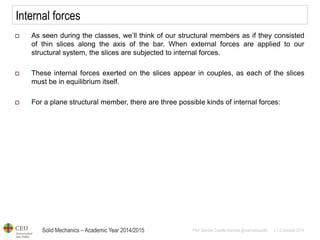
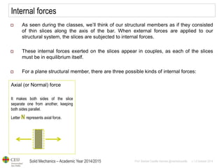
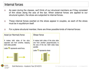
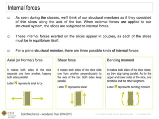
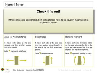
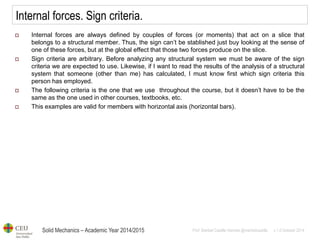
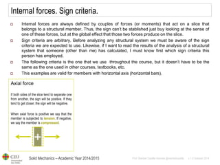
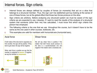
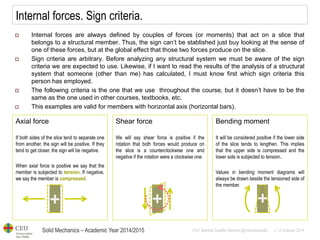
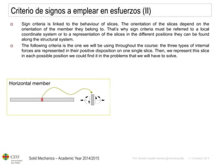
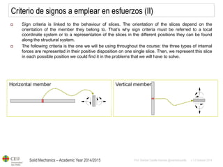
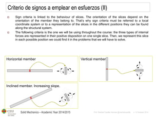
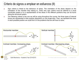
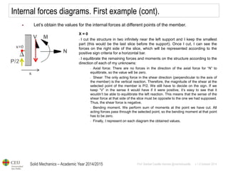
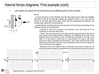
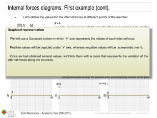
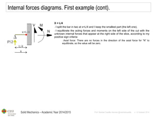
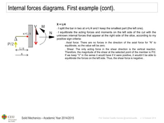
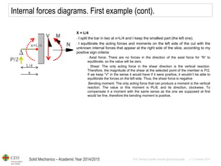
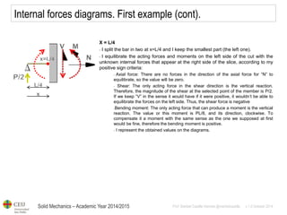
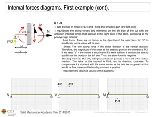
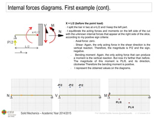
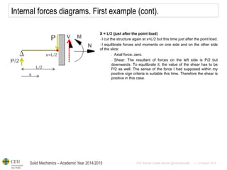
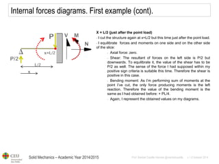
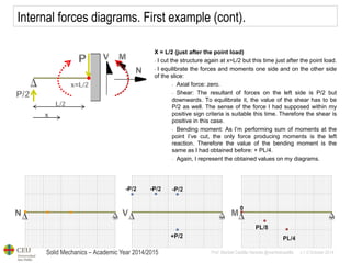
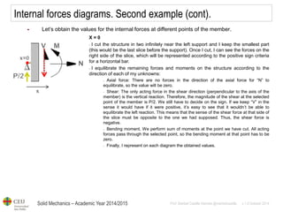
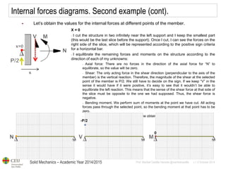
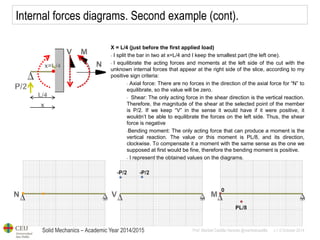
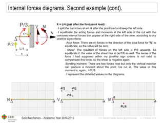
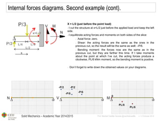
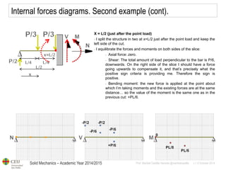
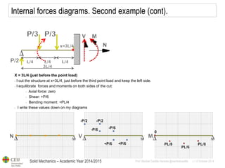
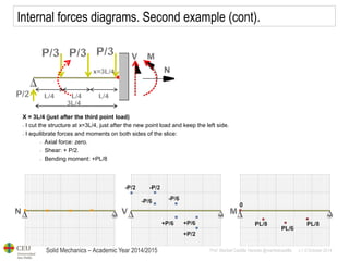
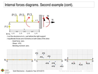
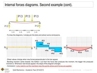
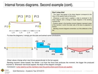
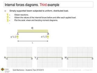
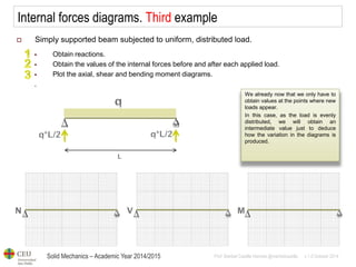
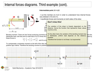
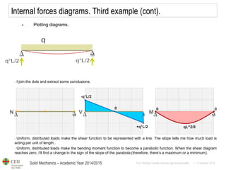
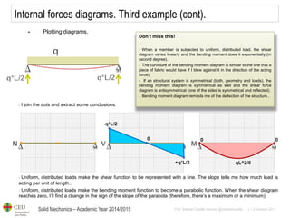
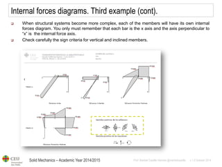
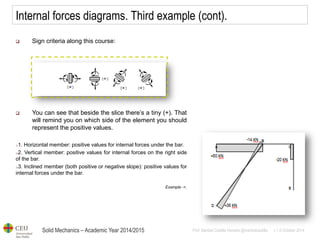

The document provides a comprehensive overview of internal forces in solid mechanics, specifically focusing on axial forces, shear forces, and bending moments as they relate to structural members. It highlights the relationship between these forces and the equilibrium of slices within the structure, detailing sign criteria for analysis. Additionally, it describes a method for calculating and representing internal forces through diagrams for structural understanding.
![THEORY OF STRUCTURES-I [B. ARCH.]](https://cdn.slidesharecdn.com/ss_thumbnails/theoryofstructures-ib-180903021950-thumbnail.jpg?width=640&height=640&fit=bounds)