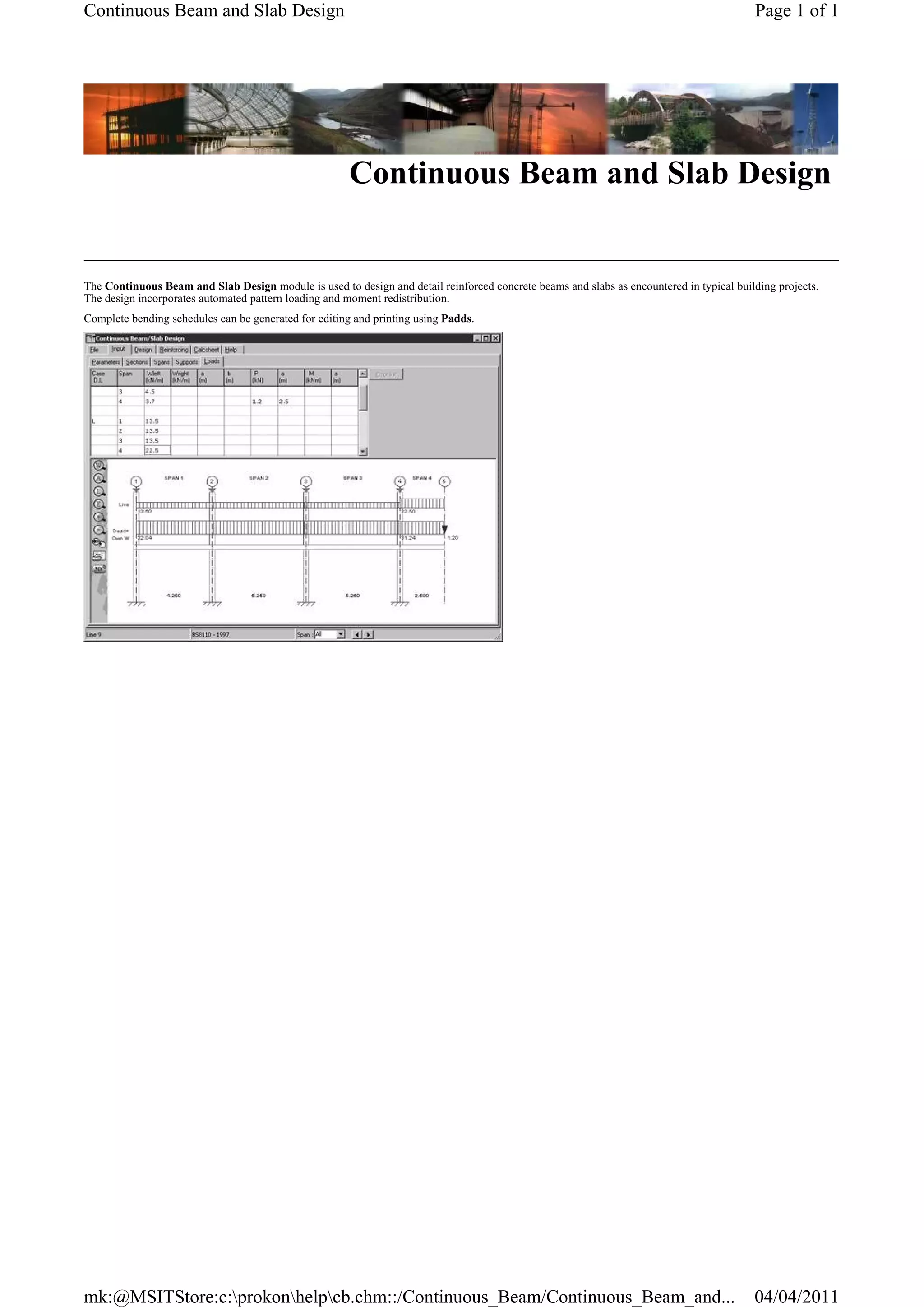
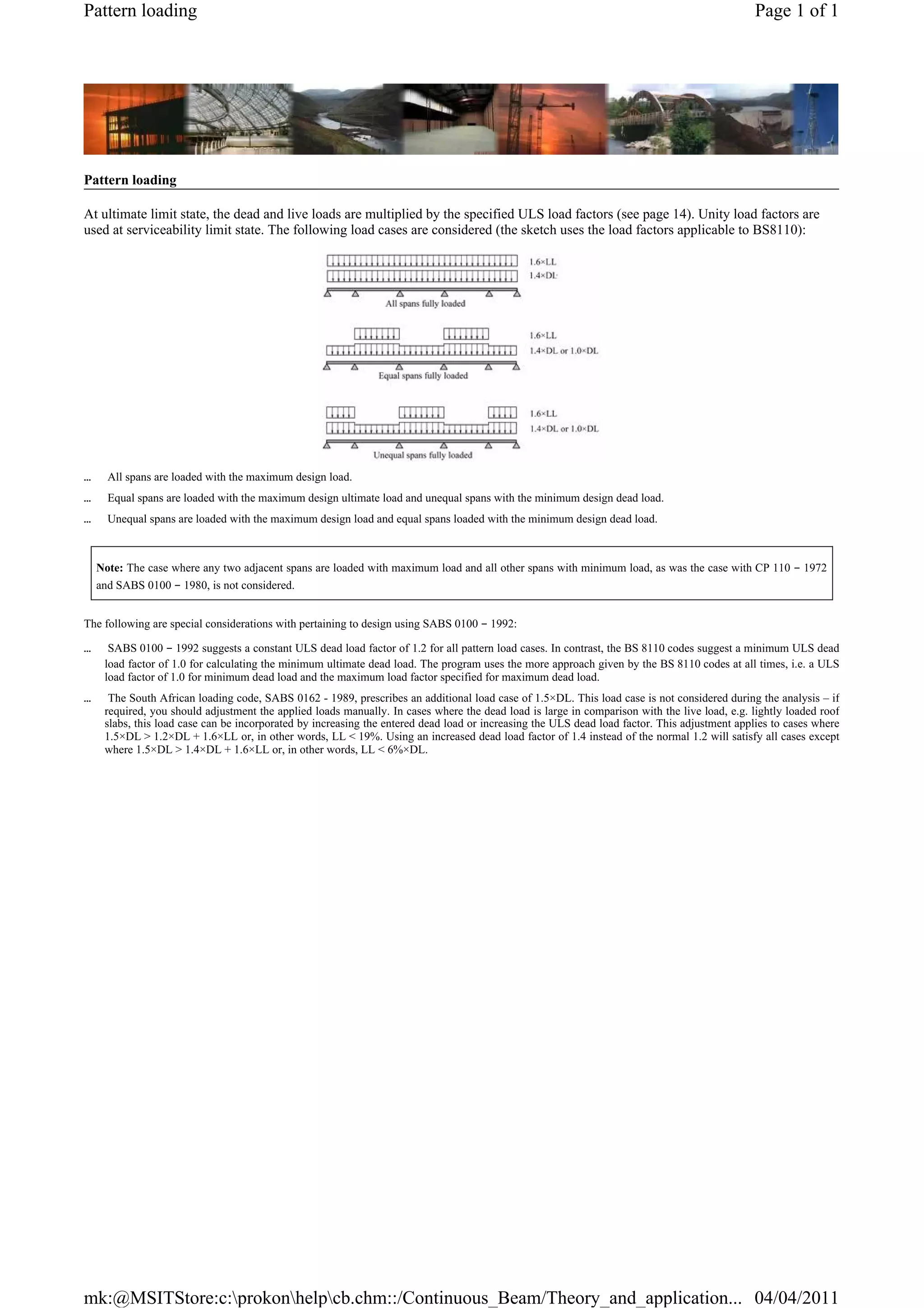
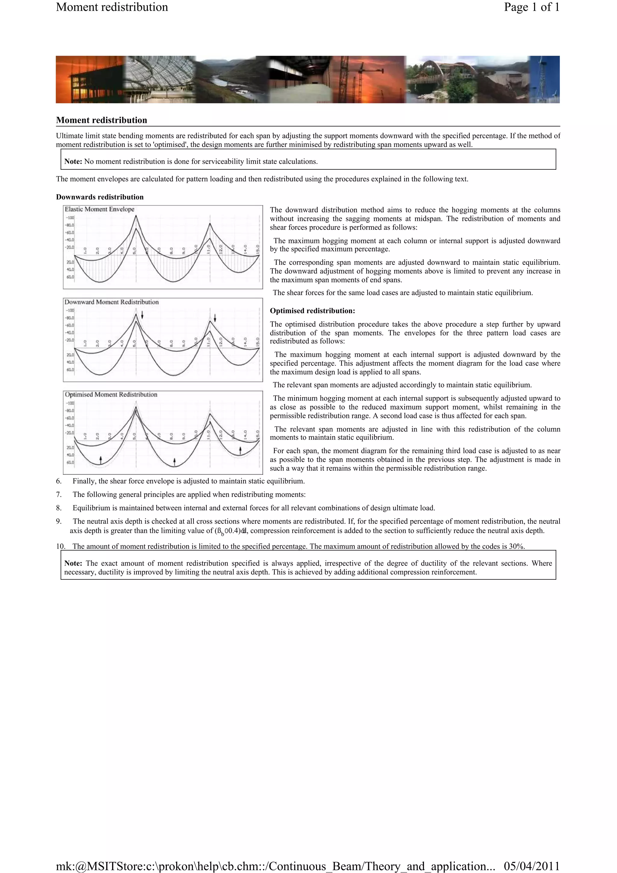
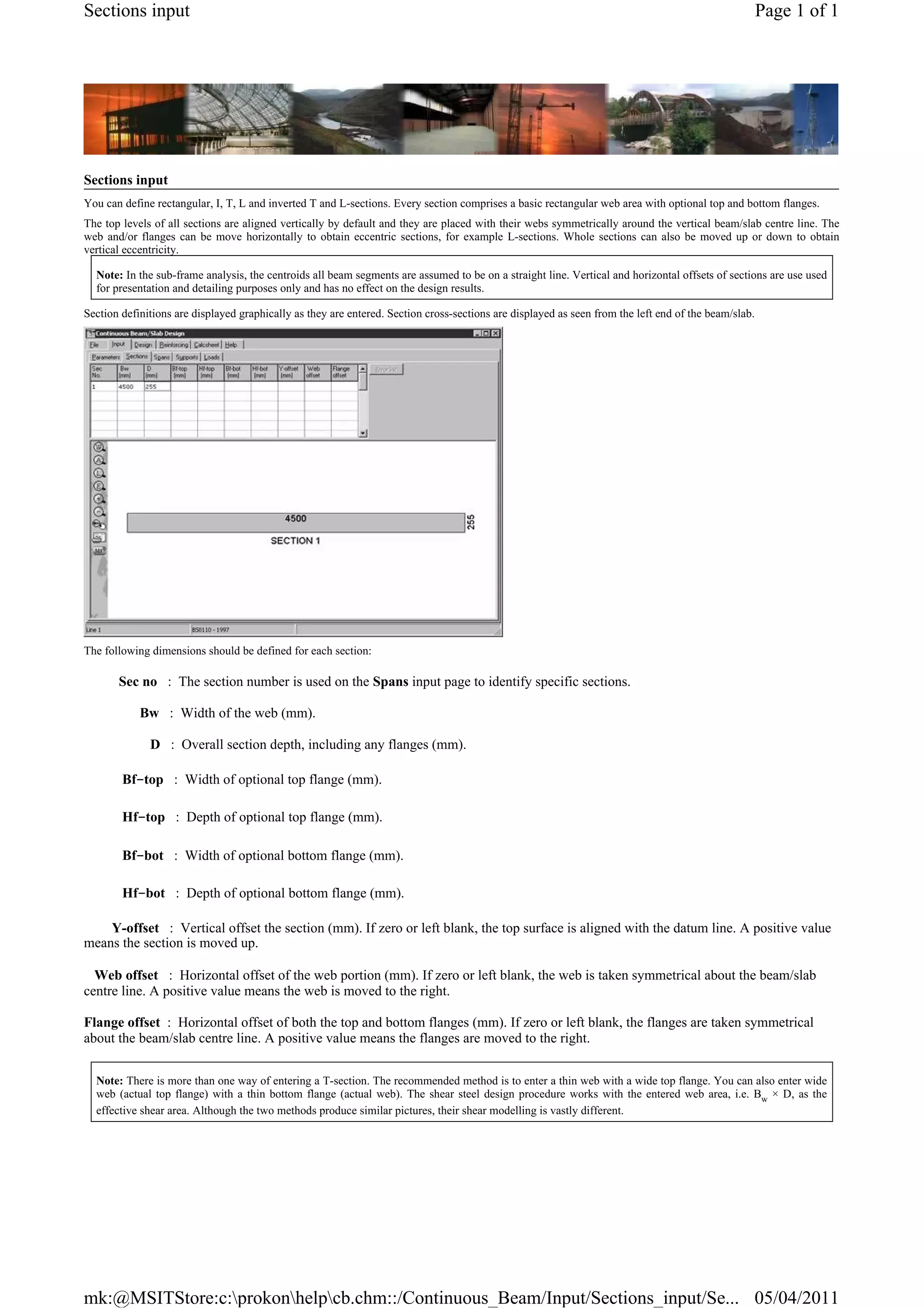
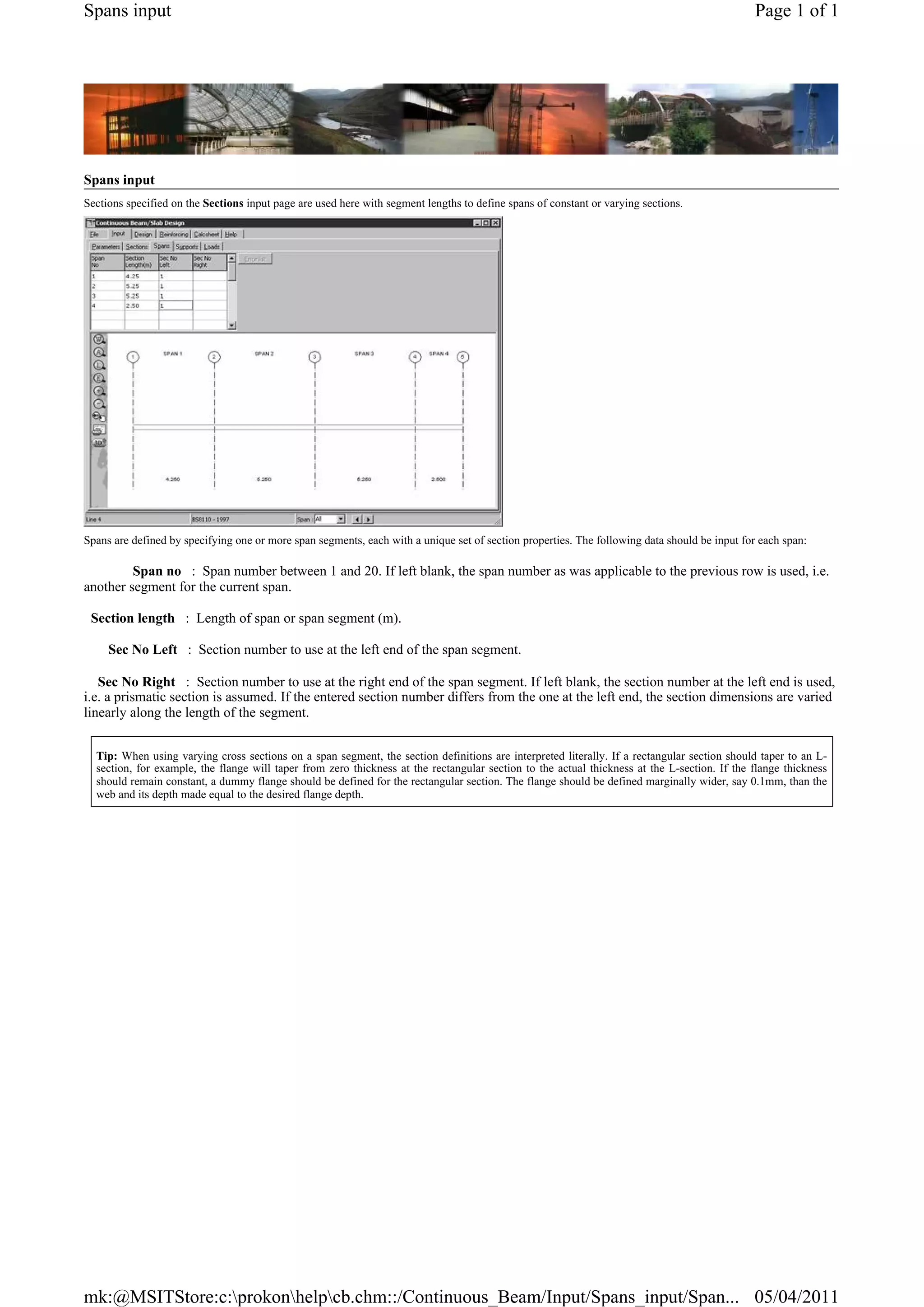
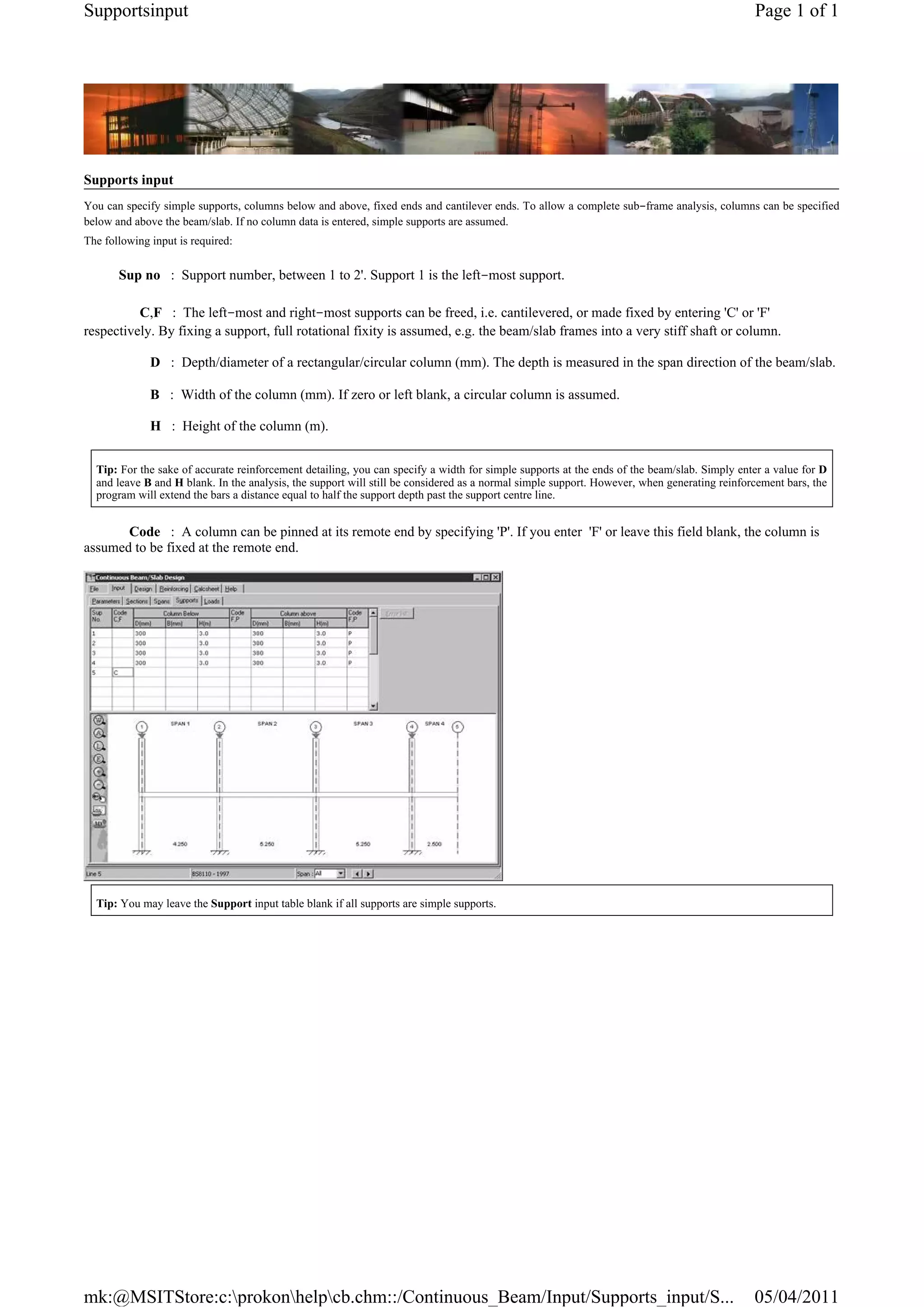
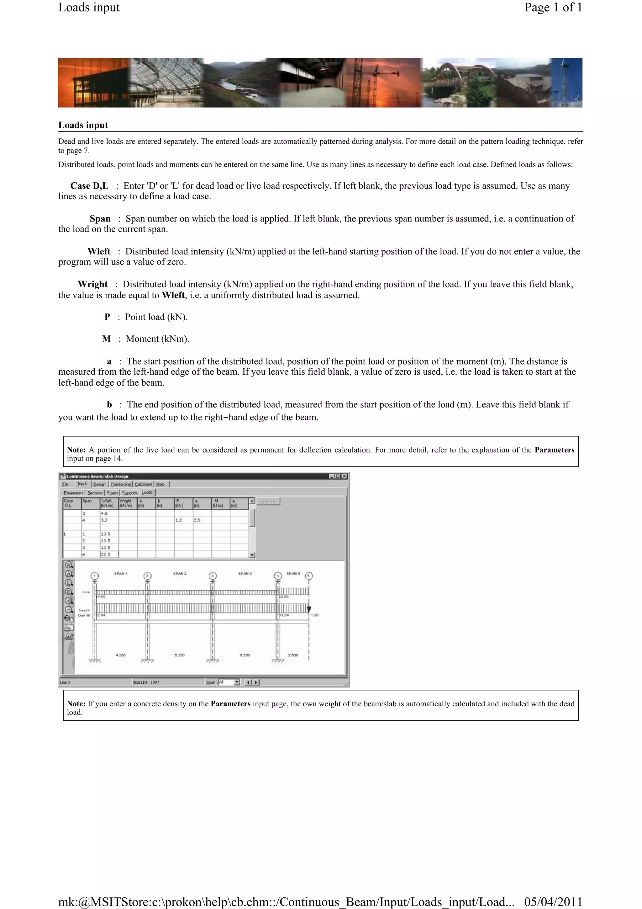
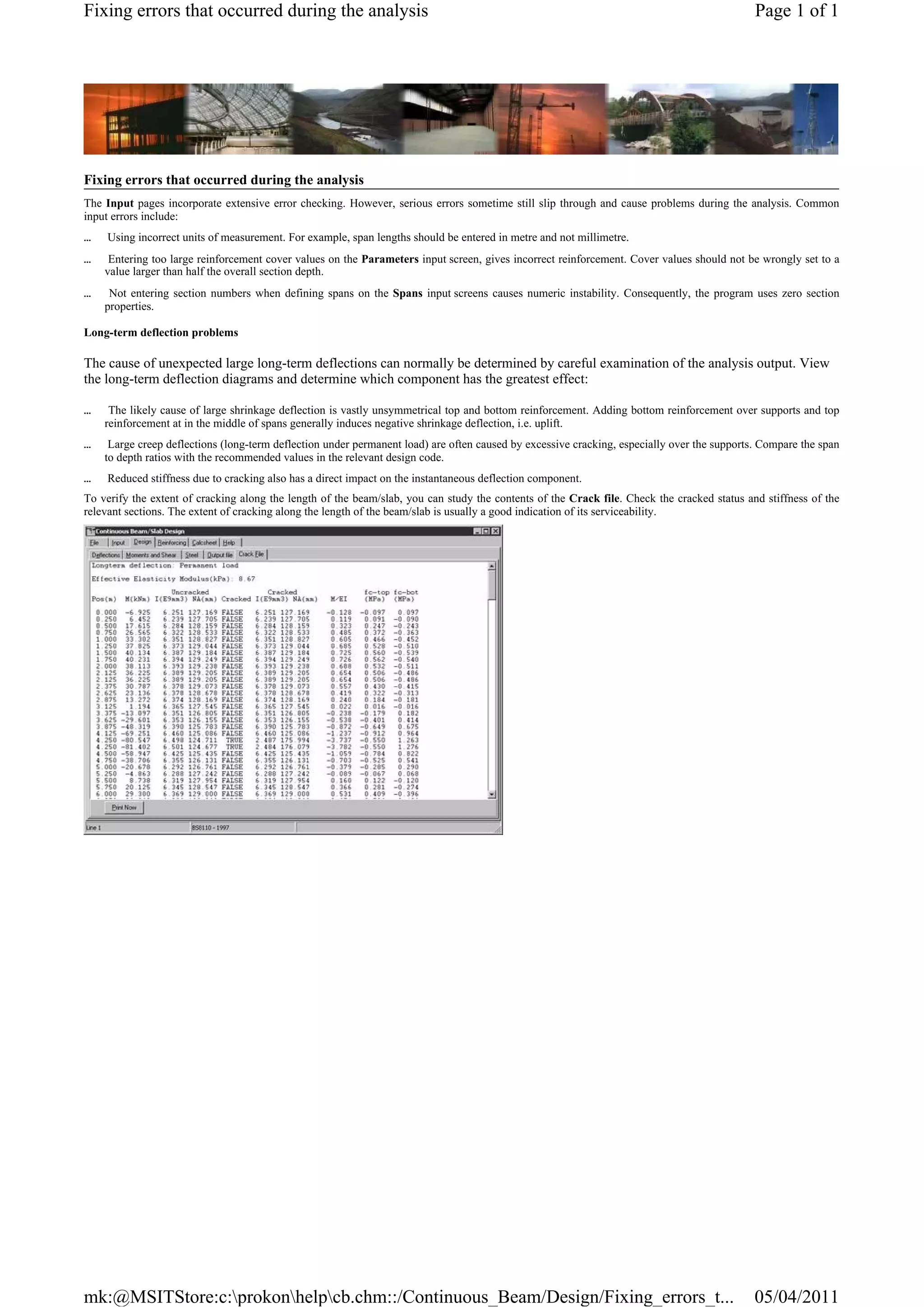
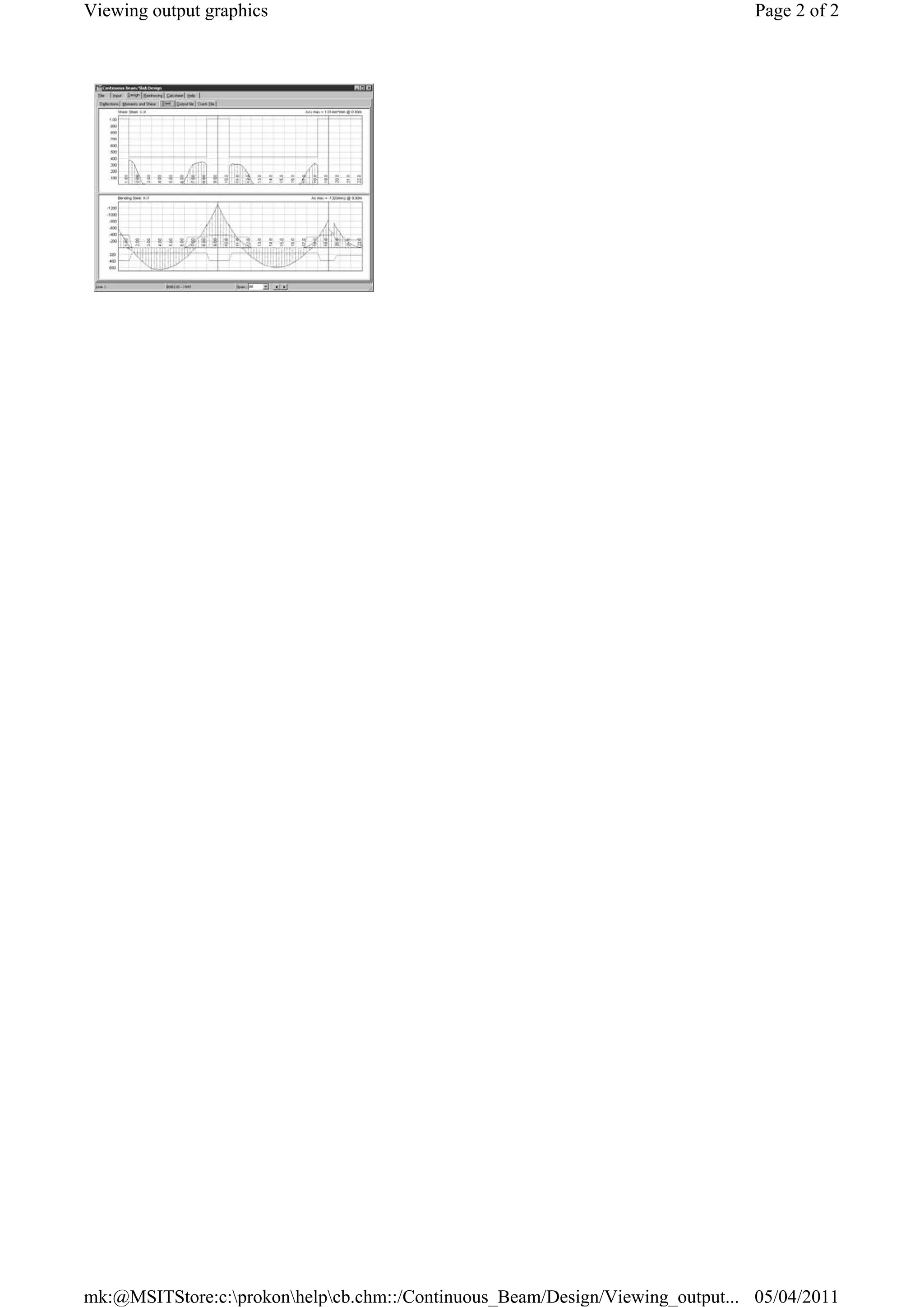
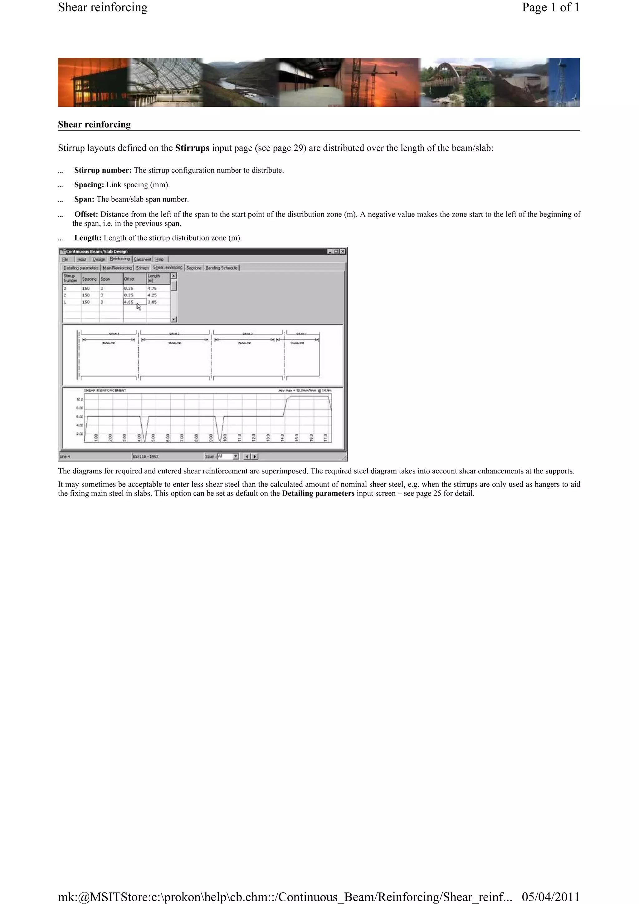
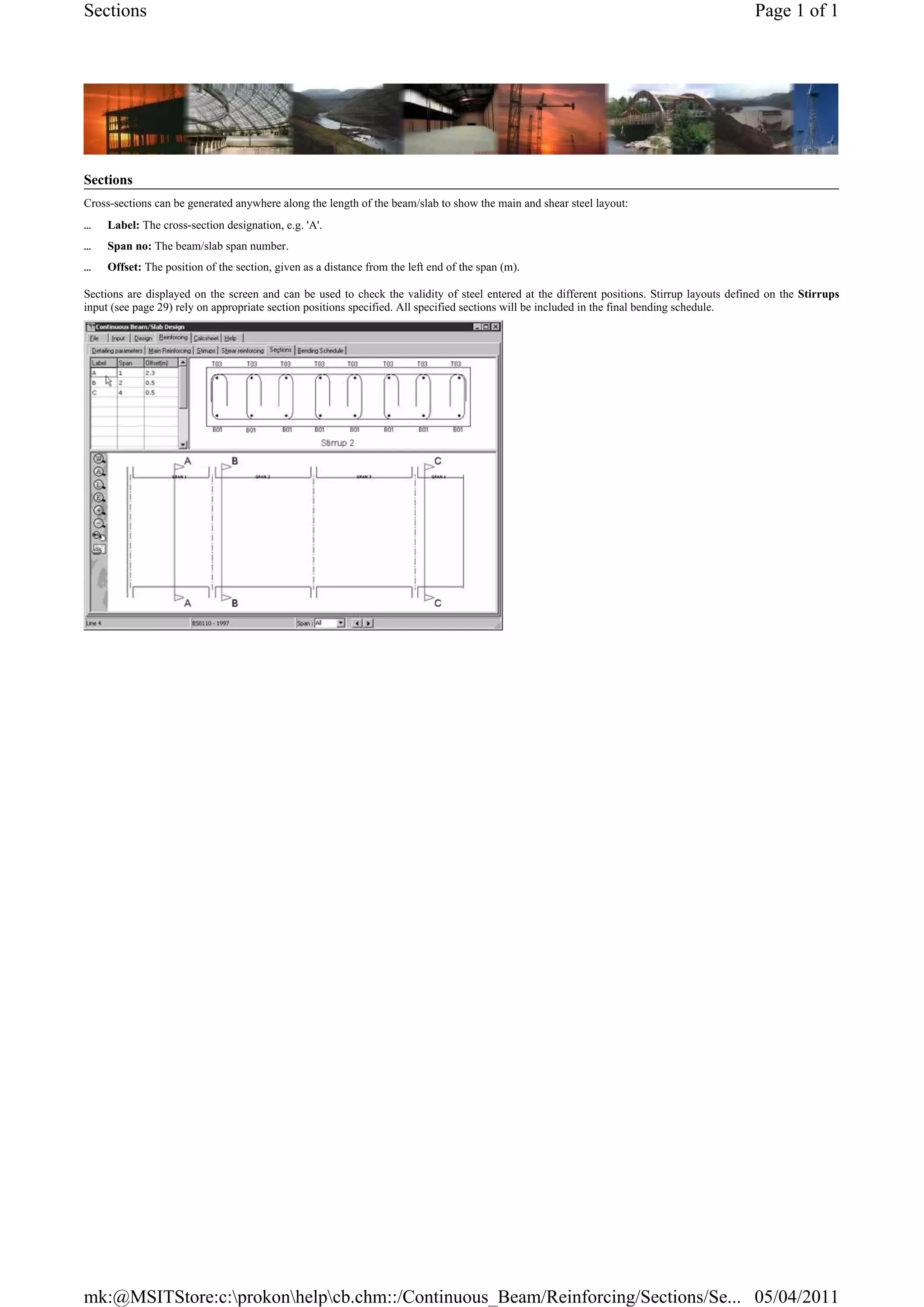
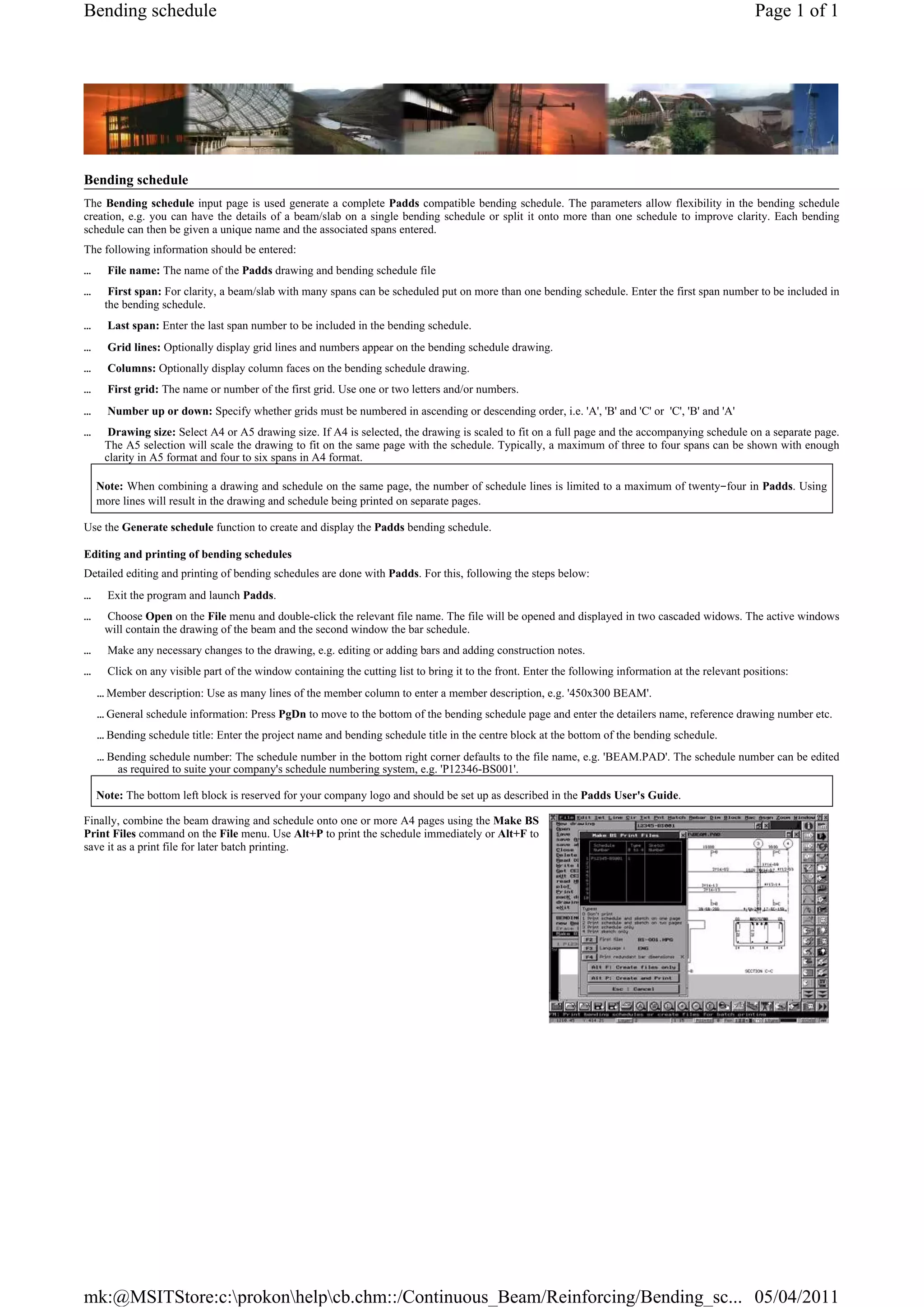
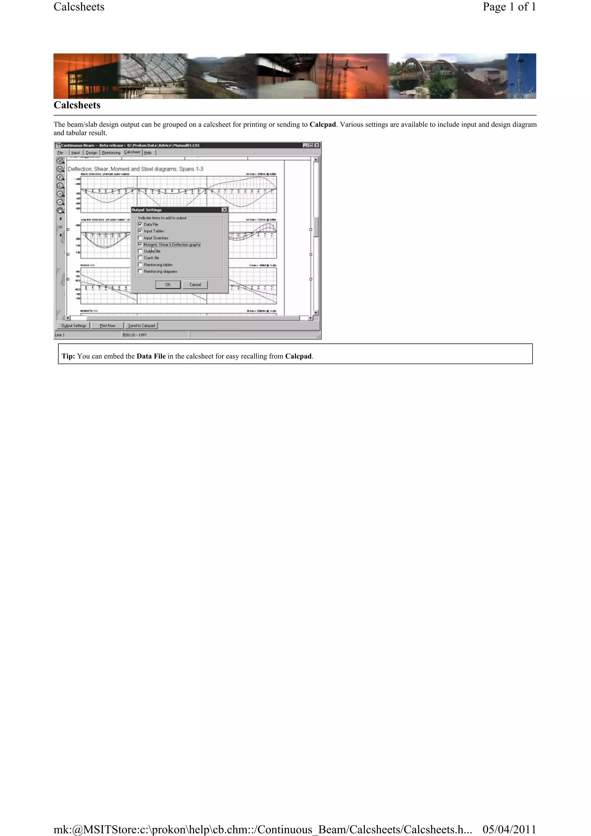
This document provides information about a software module for designing reinforced concrete beams and slabs. It describes the module's capabilities for analyzing continuous beams and slabs under pattern loading and moment redistribution. It also summarizes the module's design approach, code compliance, analysis methods, and output capabilities like bending schedules.
This document discusses the equivalent frame method for analyzing two-way slabs. It introduces the equivalent frame method, which transforms a 3D structural system into a 2D system by representing the stiffness of slab and beam members as Ksb, and the modified stiffness of columns as Kec. This allows the 3D behavior to be analyzed using conventional 2D frame analysis methods. The document then covers determining the values of Ksb and Kec to represent the slab and column stiffness in the equivalent frame.
Calulation of deflection and crack width according to is 456 2000Vikas Mehta
This document discusses the calculation of crack width in reinforced concrete flexural members. It provides information on:
1) Crack width is calculated to satisfy serviceability limits and is only relevant for Type 3 pre-stressed concrete members that crack under service loads.
2) Crack width depends on factors like amount of pre-stress, tensile stress in bars, concrete cover thickness, bar diameter and spacing, member depth and location of neutral axis, bond strength, and concrete tensile strength.
3) The method of calculation involves determining the shortest distance from the surface to a bar and using equations involving member depth, neutral axis depth, average strain at the surface level. Permissible crack widths are specified depending on exposure
Prestress loss occurs as prestress reduces over time from its initial applied value. There are two types of prestress loss - immediate losses during prestressing/transfer and long-term time-dependent losses. Immediate losses include elastic shortening, anchorage slip, and friction. Long-term losses include creep and shrinkage of concrete and relaxation of prestressing steel. The quantification of losses is based on strain compatibility between concrete and steel. For a pre-tensioned concrete sleeper, the percentage loss due to elastic shortening was calculated to be approximately 2.83% based on the stress in concrete at the level of the tendons.
This document is the Indian Standard (Part 1) for earthquake resistant design of structures. It provides general provisions and criteria for assessing earthquake hazards and designing buildings to resist earthquakes. Some key points:
- It defines seismic zones across India based on past earthquake intensities and establishes design response spectra for each zone.
- It provides minimum design forces for normal structures and notes that special structures may require more rigorous site-specific analysis.
- This revision includes changes such as defining design spectra to 6 seconds, specifying the same spectra for all building materials, including temporary structures, and provisions for irregular buildings and masonry infill walls.
- It establishes terminology used in earthquake engineering and references other relevant Indian Standards for
The document provides information on column design according to BS 8110-1:1997, including general recommendations, classifications of columns, effective length and minimum eccentricity, design moments, and design. Short columns have a length to height or breadth ratio less than 15 for braced or 10 for unbraced. Braced columns have lateral stability from walls or bracing. Additional moments are considered for slender or unbraced columns based on deflection. Design moments are calculated considering axial load and biaxial bending for different column classifications. Shear design also considers axial load and reinforcement is required if shear exceeds the shear capacity. The interaction diagram is constructed based on equilibrium equations relating stresses on a column cross section to axial load and bending
ANALYSIS AND DESIGN OF HIGH RISE BUILDING BY USING ETABSila vamsi krishna
RESULT OF ANALYSIS:
https://www.slideshare.net/ilavamsikrishna/results-of-etabs-on-high-rise-residential-buildings
ANALYSIS AND DESIGN OF BUILDING BY USING STAAD PRO PPT link :
https://www.slideshare.net/ilavamsikrishna/analysis-and-design-of-mutistoried-residential-building-by-using-staad-pro
FOR FULL REPORT:
vamsiila@gmail.com
This document contains structural design calculations for a control room and fire water tank that are part of the Madanam CPF & Pipelines Project Cauvery Asset. The calculations relate to Contract No. DLH/OES/MM/MADANAM CPF & PLP-CAUVERY/Xl1AC16002/2016 and include revisions to the calculations for the control room and fire water tank.
The document provides details on the design of a reinforced concrete column footing to support a column load of 1100kN from a 400mm square column. It describes the design process which includes determining the footing size, calculating bending moment, reinforcement requirements, checking shear capacity and development length. The design example shows a 3.5m x 3.5m square footing with 12mm diameter bars at 100mm c/c is adequate to support the given load based on the specified material properties and design codes. Reinforcement and footing details are also provided.
This document provides information about the design of strap footings. It begins with an overview of strap footings, noting they are used to connect an eccentrically loaded column footing to an interior column. The strap transmits moment caused by eccentricity to the interior footing to generate uniform soil pressure beneath both footings.
It then outlines the basic considerations for strap footing design: 1) the strap must be rigid, 2) footings should have equal soil pressures to avoid differential settlement, and 3) the strap should be out of contact with soil to avoid soil reactions. Finally, it provides the step-by-step process for designing a strap footing, including proportioning footing dimensions, evaluating soil pressures, designing reinforcement,
This document provides an overview of the design of steel beams. It discusses various beam types and sections, loads on beams, design considerations for restrained and unrestrained beams. For restrained beams, it covers lateral restraint requirements, section classification, shear capacity, moment capacity under low and high shear, web bearing, buckling, and deflection checks. For unrestrained beams, it discusses lateral torsional buckling, moment and buckling resistance checks. Design procedures and equations for determining effective properties and capacities are also presented.
This document provides information about the course "Design & Detailing of RC Structures 10CV321" taught by Dr. G.S. Suresh at NIE Mysore. It lists several reference books for the course and provides the evaluation pattern for both theory and drawing components. It also outlines the course content which includes limit state design method, stress-strain behavior of materials, assumptions in limit state design, behavior of reinforced concrete beams, stress block parameters, and calculation of ultimate flexural strength.
The document provides details to design the reinforcement for a basement retaining wall. It includes calculating the required wall thickness, loads on the wall, bending moments, shear forces, and reinforcement requirements. The summary is as follows:
1. The thickness of the basement retaining wall is determined to be 200mm based on the given height and material properties.
2. The loads on the wall, including soil pressure, water pressure, and surcharge loads are calculated.
3. The bending moment and shear force diagrams are drawn, with the maximum bending moment found to be 33.12 kNm and maximum shear force 65.76kN.
4. The required vertical and horizontal reinforcement is calculated for different sections based on
This document presents an example of analysis design of slab using ETABS. This example examines a simple single story building, which is regular in plan and elevation. It is examining and compares the calculated ultimate moment from CSI ETABS & SAFE with hand calculation. Moment coefficients were used to calculate the ultimate moment. However it is good practice that such hand analysis methods are used to verify the output of more sophisticated methods.
Also, this document contains simple procedure (step-by-step) of how to design solid slab according to Eurocode 2.The process of designing elements will not be revolutionised as a result of using Eurocode 2. Due to time constraints and knowledge, I may not be able to address the whole issues.
This document provides an overview of wind load calculation procedures according to the International Building Code (IBC) 2012 and American Society of Civil Engineers (ASCE) 7-10 standards. It defines important terms related to wind loads and explains changes made in ASCE 7-10 from the previous ASCE 7-05 standard. The major wind load calculation procedures covered are the directional procedure for buildings of all heights, the envelop procedure for low-rise buildings, and the wind tunnel procedure. Steps of the directional procedure are outlined, including determining the risk category, basic wind speed, wind parameters, velocity pressure coefficients, and velocity pressure.
This document describes the design of a pile cap by a group of civil engineering students. It defines a pile cap as a concrete mat that rests on piles driven into soft ground to provide a stable foundation. It then provides two examples of pile cap design, showing dimensions, load calculations, reinforcement requirements and construction details. The document concludes that a pile cap distributes a building's load to piles to form a stable foundation on unstable soil. It acknowledges the guidance of professors in completing this project.
This document discusses reinforced concrete columns. It begins by defining columns and different column types, including based on shape, reinforcement, loading conditions, and slenderness ratio. Short columns fail due to material strength while slender columns are at risk of buckling. The document covers column design considerations like unsupported length and effective length. It provides examples of single storey building column design and discusses minimum longitudinal reinforcement requirements in columns.
The document provides step-by-step instructions for modeling, analyzing, and designing a 10-story reinforced concrete building using ETABS. It defines the material properties, section properties, load cases, and equivalent lateral force parameters. The steps include starting a new model, defining section properties for beams, columns, slabs, and walls, assigning the sections, defining load cases, and specifying the analysis and design procedures.
This document provides an overview of reinforced concrete design principles for civil engineers and construction managers. It discusses the aim of structural design according to BS 8110, describes the properties and composite action of reinforced concrete, explains limit state design methodology, and summarizes key elements like slabs, beams, columns, walls, and foundations. The document also covers material properties, stress-strain curves, failure modes, and general procedures for slab sizing and design.
This document discusses different types and classifications of columns. It defines a column as a vertical structural member primarily designed to carry axial compression loads. Columns can be classified based on their shape, reinforcement, and type of loading. Common shapes include square, rectangular, circular, L-shaped, and T-shaped sections. Reinforcement types include tied columns with ties, spiral columns with helical reinforcement, and composite columns with encased steel. Columns are either concentrically loaded with forces through the centroid, or eccentrically loaded off-center. The document also covers column capacity calculations, resistance factors, and provides an example problem.
The document discusses the design of footings for structures. It begins by explaining that footings are needed to transfer structural loads from members made of materials like steel and concrete to the underlying soil. It then describes different types of shallow and deep foundations, including spread, strap, combined, and raft footings. The document provides details on designing isolated and combined footings to resist vertical loads and moments based on provisions in IS 456. It also discusses wall footings and combined footings that support multiple columns. In summary, the document covers the purpose of footings, various footing types, and design of isolated and combined footings.
This document provides details on the structural design of buried pipelines under various loading conditions according to British standards. It outlines assumptions made, references used, and notes on the design process. The design involves selecting an appropriate pipe strength and bedding combination that can withstand permanent and transient loads over the pipe's 120-year design life. Various parameters are calculated, such as soil and water loads, and checked against the pipe's minimum crushing strength to ensure it satisfies the required safety factor.
Etabs example-rc building seismic load response-Bhaskar Alapati
This document provides step-by-step instructions for performing a modal response spectra analysis and design of a 10-story reinforced concrete building model in ETABS. It describes opening an existing model, defining response spectrum functions and cases based on IBC2000 parameters, running a modal analysis and response spectral analysis, and reviewing results including mode shapes, member forces, and designing concrete frames and shear walls. The objective is to demonstrate modal response spectra analysis and design of the building model according to IBC2000 seismic code provisions.
The document discusses the design of a combined footing to support two columns. It first defines what a combined footing is and why it is used. It then describes the types of combined footings and the forces acting on it. The document provides the design steps for a rectangular combined footing, which include determining dimensions, reinforcement requirements, and design checks. As an example, it shows the detailed design of a rectangular combined footing supporting two columns with loads of 450kN and 650kN respectively. The design includes calculating dimensions, reinforcement, development lengths, and design checks.
23-Design of Column Base Plates (Steel Structural Design & Prof. Shehab Mourad)Hossam Shafiq II
This document discusses the design of column base plates to resist both axial loads and bending moments. It provides equations to calculate stresses on the base plate and footing. It then gives an example of designing a base plate for a column supporting an axial load of 1735 kN and bending moment of 200 kN.m. The design process involves calculating eccentricity, base plate dimensions, stresses on the footing, required plate thickness, and checking bending in two directions. The example concludes by specifying a base plate of dimensions 750mm x 500mm x 40mm that satisfies all design requirements.
Ring or circular rafts can be used for cylindrical structures such as chimneys, silos, storage tanks, TV-towers and other structures. In this case, ring or circular raft is the best suitable foundation to the natural geometry of such structures. The design of circular rafts is quite similar to that of other rafts.
This document is a structural design report for a proposed residential building in Kirtipur, Nepal. It provides details on the structural system, materials, design codes followed, load calculations, structural dimensions, analysis, and design procedures. The building will be a 3.5 story ductile moment resisting frame structure with reinforced concrete beams, columns, slabs, and footings. Load calculations are provided for dead and live loads according to Nepalese codes. Analysis was conducted using ETABS software to calculate member forces and design seismic loads. The report concludes with sample output data from the structural analysis.
The document discusses reinforced concrete columns, including their functions, failure modes, classifications, and design considerations. Columns primarily resist axial compression but may also experience bending moments. They can fail due to compression, buckling, or a combination. Design depends on whether the column is short or slender, braced or unbraced. Reinforcement is designed based on the column's expected loads and dimensions using methods specified in design codes like BS 8110.
The document summarizes the design procedures for slab systems according to the ACI 318 Code, including:
1) The direct design method and equivalent frame method for determining moments at critical sections.
2) Distributing the total design moment between positive and negative moments.
3) Distributing moments laterally between column strips, middle strips, and beams.
4) A 5-step basic design procedure involving determining moments, distributing moments, sizing reinforcement, and designing beams if present.
Heavier machinery operating at faster speeds has made simplified structural design approaches unsafe. Dynamic analysis using SAP2000 can accurately model structural response under vibratory loads. This tutorial provides guidance on modeling vibrating equipment in SAP2000 to analyze dynamic effects on the supporting structure. Key steps include adding joints for equipment centers of mass and unbalanced loads, connecting them to the structure with constraints, defining vibration functions based on equipment speeds, and running time history analyses.
Stress Analysis of a heavy duty vehicle chassis by using FEADigitech Rathod
This document summarizes a seminar presentation on stress analysis of a heavy duty vehicle chassis using finite element analysis (FEA). The presentation covers the methodology used, which includes modeling the full-scale chassis in CATIA, applying a uniform load distribution in ANSYS, and analyzing stress distributions and deformations. The results show maximum von Mises stresses of 200.67 MPa and deformations of 8.15mm between frame members. Modifications to the cross-section dimensions and connections are suggested to reduce stresses and deformations at critical points and increase chassis life.
Modal analysis determines the natural vibration characteristics of a structure. Natural frequency depends on mass, stiffness, and boundary conditions, and is important to understand possible resonance. Resonance occurs when natural frequency coincides with excitation frequency, and can cause excessive deformation. The document provides an example modal analysis of a simply supported aluminum plate, calculating its natural frequencies. Finite element analysis is used to model the system and structures are substantiated to have sufficient margin of safety under limit loads.
The document summarizes the analysis and design of trusses for a Jordanian synchrotron roof structure. It describes the project, loads on the structure, and the analysis process. The trusses were analyzed using structural analysis software. The design process for tension and compression members is then outlined, including selecting sections, checking capacities and slenderness ratios. Examples of designing a compression member and tension member are provided. Finally, the document discusses the procedure for designing truss connections, including determining the number and spacing of bolts.
This document summarizes a senior project analyzing the ultimate strength of aircraft structures through testing and analysis. A group of students analyzed and tested beams with different cross-sectional shapes to study local buckling effects on strength, following methods from a paper by their advisor Dr. Todd Coburn. The project involved analyzing critical cross-sections using plastic bending analysis and Cozzone's method. It also developed a hybrid procedure accounting for material non-linearity, flange stability, and other factors influencing ultimate strength. The procedure determines strain distributions and calculates ultimate moments based on stress-strain curves for each section element.
Design of concrete structure 2 project-Loay Qabaha &Basel SalameLoay Qabaha
This document provides a design for a two-way ribbed slab system. It begins by defining two-way slab systems and providing structural equations. It then gives the problem definition, including load data. The slab is designed by first assuming a thickness and checking loads and shear. Reinforcement is designed. Frame analysis is done by hand and in SAP2000 to calculate moments, which are within 5% error. Design details like steel areas are attached in an Excel sheet.
This document describes various analysis methods for modeling active and passive damping in structures using NX I-deas and NX Nastran software. It discusses modeling constrained layer damping, piezoelectric fibers, and viscoelastic damping materials to increase structural damping. Examples are provided of applying these methods to design damping treatments for a spacecraft and liquid rocket engine. The key methods allow identifying important vibration modes, estimating modal damping contributions of candidate materials, and predicting changes to modal damping and forced response with added damping treatments.
This document is an installation and operation manual that provides technical specifications and instructions for constant hangers. It includes:
- An overview of the product groups and load/travel ranges for LISEGA standard supports, including constant hangers, spring hangers, snubbers, and other piping components.
- Details on the modular system used, including compatible load groups, statically vs dynamically determined components, and the coding system for product type designations.
- Instructions for transporting, storing, and installing constant hangers, which are mechanically acting support devices. Diagrams are provided to identify the parts of constant hangers.
A finite element analysis was performed on a 6 bay plane truss structure using ABAQUS software to determine deflections and member forces under tension, shear, and bending loads. The results were used to calculate equivalent cross-sectional properties, assuming the truss behaved like a cantilever beam. Additional analysis was conducted using fully stressed design to minimize the structure's weight by resizing members to be fully stressed at their allowable limit of 100 MPa under at least one load case, while maintaining a minimum gauge of 0.1 cm^2. Iterative resizing reduced member areas and increased stresses until all members were fully stressed at their limits.
IRJET- Non-Linear Contact Analysis and Design Optimisation of Load Cell for H...IRJET Journal
This document describes a study analyzing and optimizing the design of a high capacity 600-ton load cell using finite element analysis. The initial design analysis found stresses exceeding allowable levels. Modifications including adding a 2mm fillet radius and bottom plate were analyzed. With modifications, stresses at the strain gauge region were reduced to acceptable levels below 148.28 N/mm^2, improving the design for high capacity applications. Finite element analysis with MSC Nastran and PATRAN was used to evaluate stresses and optimize the load cell design.
Stress Analysis on Human Powered Vehicle FrameWilliam Steppe
The document summarizes the analysis and design process of a recumbent tricycle frame for a competition. Finite element analysis was performed on initial frame designs to evaluate stress levels and safety factors. The frame design was iteratively improved by changing materials, adding fillets, and increasing tube sizes and wall thicknesses. This lowered stresses and increased safety factors. A CFD analysis found drag forces to be negligible. A mesh independence study validated the accuracy of simulation results. The optimized frame design met requirements for the competition.
The document discusses code provisions for calculating the effective span of slabs according to IS 456. It describes how to calculate the effective span for simply supported, continuous, and cantilever members. It also discusses load assumptions, reinforcement cover requirements, deflection limits, and provides an overview of one-way slabs, two-way slabs, flat slabs, and flat plates.
This document provides definitions and analysis procedures for seismic isolation design. Some key points:
- It outlines criteria for bearings used in seismic isolation design that supplement other AASHTO specifications.
- The criteria are intended for horizontal isolation systems using passive isolator units to provide flexibility and damping.
- It defines terms related to seismic isolation like design displacement, effective damping, isolator unit, etc.
- Analysis procedures include using a bilinear model of the isolator, and performing upper and lower bound analyses with maximum and minimum isolator properties unless displacements and forces vary less than 15%.
- For structures over 3 seconds, a nonlinear time-history analysis is required. Over 30% damping requires a
User guide of paleo-structure restoration module v2.2.0Bo Sun
This document provides a user guide for a paleo-structure restoration module. The module allows restoration of multi-stage complex structures based on tectonic evolution principles. It quantitatively describes tectonic activity and demonstrates the evolution process in 3D models. The module uses tools like erosion restoration, inclined shear, flexural slip, unfolding and flattening beds to restore structures. Parameters for the tools and the restoration workflow are described.
Structural Integrating of Ladder Type Heavy Load Automotive Chassis and its O...IRJET Journal
1. The document describes structural analysis and optimization of a heavy vehicle ladder-type chassis.
2. The chassis is modeled in CATIA and analyzed in ANSYS to determine stress and deformation under load.
3. To reduce weight, a slot is created in the chassis frame in a region of minimum deformation. Optimization of the slot shape is then performed in ANSYS.
IRJET- Design Analysis of a Automotive Shock Absorber AssemblyIRJET Journal
This document summarizes a study analyzing the design of an automotive shock absorber assembly. Finite element analysis using ABAQUS software was conducted to evaluate the assembly's performance under static and dynamic loading conditions. The static stress analysis found a maximum deflection of 29.4 mm and maximum stresses of 117 MPa at corners and 215 MPa in springs. Modal analysis determined the first ten natural vibration modes and identified the first natural frequency as 42.7 Hz, indicating a stiffer suspension. The study concluded the design provides adequate safety with room for further weight optimization to improve comfort while maintaining structural integrity under expected loads.
The document discusses fatigue analysis of welded assemblies using ANSYS Workbench. It proposes a workflow involving 6 steps: 1) importing the CAD model and defeature it, 2) solving the global model to identify critical spots, 3) generating submodels from the CAD at critical spots, 4) meshing and interpolating loads to the submodel, 5) solving the submodel to determine the stress state, and 6) using an effective notch stress concept and the Fatigue tool to calculate fatigue life. The key strengths are maintaining geometric consistency between models, running the global model once to enable multiple submodels, and the ability to efficiently study design variants.
Similar to 89505650 concrete-beam-and-slab-design-using-prokon (20)
Literature Review Basics and Understanding Reference Management.pptxDr Ramhari Poudyal
Three-day training on academic research focuses on analytical tools at United Technical College, supported by the University Grant Commission, Nepal. 24-26 May 2024
Using recycled concrete aggregates (RCA) for pavements is crucial to achieving sustainability. Implementing RCA for new pavement can minimize carbon footprint, conserve natural resources, reduce harmful emissions, and lower life cycle costs. Compared to natural aggregate (NA), RCA pavement has fewer comprehensive studies and sustainability assessments.
We have compiled the most important slides from each speaker's presentation. This year’s compilation, available for free, captures the key insights and contributions shared during the DfMAy 2024 conference.
Embedded machine learning-based road conditions and driving behavior monitoringIJECEIAES
Car accident rates have increased in recent years, resulting in losses in human lives, properties, and other financial costs. An embedded machine learning-based system is developed to address this critical issue. The system can monitor road conditions, detect driving patterns, and identify aggressive driving behaviors. The system is based on neural networks trained on a comprehensive dataset of driving events, driving styles, and road conditions. The system effectively detects potential risks and helps mitigate the frequency and impact of accidents. The primary goal is to ensure the safety of drivers and vehicles. Collecting data involved gathering information on three key road events: normal street and normal drive, speed bumps, circular yellow speed bumps, and three aggressive driving actions: sudden start, sudden stop, and sudden entry. The gathered data is processed and analyzed using a machine learning system designed for limited power and memory devices. The developed system resulted in 91.9% accuracy, 93.6% precision, and 92% recall. The achieved inference time on an Arduino Nano 33 BLE Sense with a 32-bit CPU running at 64 MHz is 34 ms and requires 2.6 kB peak RAM and 139.9 kB program flash memory, making it suitable for resource-constrained embedded systems.
Electric vehicle and photovoltaic advanced roles in enhancing the financial p...IJECEIAES
Climate change's impact on the planet forced the United Nations and governments to promote green energies and electric transportation. The deployments of photovoltaic (PV) and electric vehicle (EV) systems gained stronger momentum due to their numerous advantages over fossil fuel types. The advantages go beyond sustainability to reach financial support and stability. The work in this paper introduces the hybrid system between PV and EV to support industrial and commercial plants. This paper covers the theoretical framework of the proposed hybrid system including the required equation to complete the cost analysis when PV and EV are present. In addition, the proposed design diagram which sets the priorities and requirements of the system is presented. The proposed approach allows setup to advance their power stability, especially during power outages. The presented information supports researchers and plant owners to complete the necessary analysis while promoting the deployment of clean energy. The result of a case study that represents a dairy milk farmer supports the theoretical works and highlights its advanced benefits to existing plants. The short return on investment of the proposed approach supports the paper's novelty approach for the sustainable electrical system. In addition, the proposed system allows for an isolated power setup without the need for a transmission line which enhances the safety of the electrical network
Presentation of IEEE Slovenia CIS (Computational Intelligence Society) Chapte...University of Maribor
Slides from talk presenting:
Aleš Zamuda: Presentation of IEEE Slovenia CIS (Computational Intelligence Society) Chapter and Networking.
Presentation at IcETRAN 2024 session:
"Inter-Society Networking Panel GRSS/MTT-S/CIS
Panel Session: Promoting Connection and Cooperation"
IEEE Slovenia GRSS
IEEE Serbia and Montenegro MTT-S
IEEE Slovenia CIS
11TH INTERNATIONAL CONFERENCE ON ELECTRICAL, ELECTRONIC AND COMPUTING ENGINEERING
3-6 June 2024, Niš, Serbia
1. Continuous Beam and Slab Design
The Continuous Beam and Slab Design module is used to design and detail reinforced concrete beams and slabs as encountered in typical building projects.
The design incorporates automated pattern loading and moment redistribution.
Complete bending schedules can be generated for editing and printing using Padds.
Page 1 of 1Continuous Beam and Slab Design
04/04/2011mk:@MSITStore:c:prokonhelpcb.chm::/Continuous_Beam/Continuous_Beam_and...
2. Theory and application
The following text gives an overview of the theory and application of the design codes.
Page 1 of 1Theory and application
04/04/2011mk:@MSITStore:c:prokonhelpcb.chm::/Continuous_Beam/Theory_and_application...
3. Design scope
The program designs and details continuous concrete beams and slabs. You can design structures ranging from simply supported single span to twenty-span
continuous beams and slabs. Cross-sections can include a mixture rectangular, I, T and L-sections. Spans can have constant or tapered sections.
Entered dead and live loads are automatically applied as pattern loads during the analysis. At ultimate limit state, moments and shears are redistributed to a
specified percentage.
Reinforcement can be generated for various types of beams and slabs, edited and saved as Padds compatible bending schedules.
Page 1 of 1Design scope
04/04/2011mk:@MSITStore:c:prokonhelpcb.chm::/Continuous_Beam/Theory_and_application...
4. Design codes
The following codes are supported:
x BS 8110 - 1985.
x BS 8110 - 1997.
x SABS 0100 - 1992.
Reinforcement bending schedules are generated in accordance to the guidelines given by the following publications:
x General principles: BS 4466 and SABS 082.
x Guidelines for detailing: 'Standard Method of Detailing Structural Concrete' published by the British Institute of Structural Engineers.
Page 1 of 1Design codes
04/04/2011mk:@MSITStore:c:prokonhelpcb.chm::/Continuous_Beam/Theory_and_application...
5. Sub-frame analysis
A two-dimensional frame model is constructed from the input data. Section properties are based on the gross uncracked concrete sections. Columns can
optionally be specified below and above the beam/slab and can be made pinned or fixed at their remote ends.
Note: No checks are made for the slenderness limits of columns or beam flanges.
Page 1 of 1Sub-frame analysis
04/04/2011mk:@MSITStore:c:prokonhelpcb.chm::/Continuous_Beam/Theory_and_application...
6. Pattern loading
At ultimate limit state, the dead and live loads are multiplied by the specified ULS load factors (see page 14). Unity load factors are
used at serviceability limit state. The following load cases are considered (the sketch uses the load factors applicable to BS8110):
x All spans are loaded with the maximum design load.
x Equal spans are loaded with the maximum design ultimate load and unequal spans with the minimum design dead load.
x Unequal spans are loaded with the maximum design load and equal spans loaded with the minimum design dead load.
Note: The case where any two adjacent spans are loaded with maximum load and all other spans with minimum load, as was the case with CP 110 - 1972
and SABS 0100 - 1980, is not considered.
The following are special considerations with pertaining to design using SABS 0100 - 1992:
x SABS 0100 - 1992 suggests a constant ULS dead load factor of 1.2 for all pattern load cases. In contrast, the BS 8110 codes suggest a minimum ULS dead
load factor of 1.0 for calculating the minimum ultimate dead load. The program uses the more approach given by the BS 8110 codes at all times, i.e. a ULS
load factor of 1.0 for minimum dead load and the maximum load factor specified for maximum dead load.
x The South African loading code, SABS 0162 - 1989, prescribes an additional load case of 1.5×DL. This load case is not considered during the analysis – if
required, you should adjustment the applied loads manually. In cases where the dead load is large in comparison with the live load, e.g. lightly loaded roof
slabs, this load case can be incorporated by increasing the entered dead load or increasing the ULS dead load factor. This adjustment applies to cases where
1.5×DL > 1.2×DL + 1.6×LL or, in other words, LL < 19%. Using an increased dead load factor of 1.4 instead of the normal 1.2 will satisfy all cases except
where 1.5×DL > 1.4×DL + 1.6×LL or, in other words, LL < 6%×DL.
Page 1 of 1Pattern loading
04/04/2011mk:@MSITStore:c:prokonhelpcb.chm::/Continuous_Beam/Theory_and_application...
Not needed for bs 8110 design
7. Moment redistribution
Ultimate limit state bending moments are redistributed for each span by adjusting the support moments downward with the specified percentage. If the method of
moment redistribution is set to 'optimised', the design moments are further minimised by redistributing span moments upward as well.
Note: No moment redistribution is done for serviceability limit state calculations.
The moment envelopes are calculated for pattern loading and then redistributed using the procedures explained in the following text.
Downwards redistribution
The downward distribution method aims to reduce the hogging moments at the columns
without increasing the sagging moments at midspan. The redistribution of moments and
shear forces procedure is performed as follows:
1. The maximum hogging moment at each column or internal support is adjusted downward
by the specified maximum percentage.
2. The corresponding span moments are adjusted downward to maintain static equilibrium.
The downward adjustment of hogging moments above is limited to prevent any increase in
the maximum span moments of end spans.
3. The shear forces for the same load cases are adjusted to maintain static equilibrium.
Optimised redistribution:
The optimised distribution procedure takes the above procedure a step further by upward
distribution of the span moments. The envelopes for the three pattern load cases are
redistributed as follows:
1. The maximum hogging moment at each internal support is adjusted downward by the
specified percentage. This adjustment affects the moment diagram for the load case where
the maximum design load is applied to all spans.
2. The relevant span moments are adjusted accordingly to maintain static equilibrium.
3. The minimum hogging moment at each internal support is subsequently adjusted upward to
as close as possible to the reduced maximum support moment, whilst remaining in the
permissible redistribution range. A second load case is thus affected for each span.
4. The relevant span moments are adjusted in line with this redistribution of the column
moments to maintain static equilibrium.
5. For each span, the moment diagram for the remaining third load case is adjusted to as near
as possible to the span moments obtained in the previous step. The adjustment is made in
such a way that it remains within the permissible redistribution range.
6. Finally, the shear force envelope is adjusted to maintain static equilibrium.
7. The following general principles are applied when redistributing moments:
8. Equilibrium is maintained between internal and external forces for all relevant combinations of design ultimate load.
9. The neutral axis depth is checked at all cross sections where moments are redistributed. If, for the specified percentage of moment redistribution, the neutral
axis depth is greater than the limiting value of (ßb0.4)˜d, compression reinforcement is added to the section to sufficiently reduce the neutral axis depth.
10. The amount of moment redistribution is limited to the specified percentage. The maximum amount of redistribution allowed by the codes is 30%.
Note: The exact amount of moment redistribution specified is always applied, irrespective of the degree of ductility of the relevant sections. Where
necessary, ductility is improved by limiting the neutral axis depth. This is achieved by adding additional compression reinforcement.
Page 1 of 1Moment redistribution
05/04/2011mk:@MSITStore:c:prokonhelpcb.chm::/Continuous_Beam/Theory_and_application...
8. Deflection calculation
Both short-term and long-term deflections are calculated. No moment redistribution is done at serviceability limit state.
Elastic deflections
Short-term elastic deflections are calculated using unfactored SLS pattern loading. Gross uncracked concrete sections are used.
Long-term deflections
Long-term deflections are determined by first calculating the cracked transformed sections:
1. The full SLS design load is applied to all spans to obtain the elastic moment diagram.
2. The cracked transformed sections are then calculated at 250 mm intervals along the length of the beam. The results of these calculations are tabled in the
Crack files on the View output pages.
Note: The calculation of the cracked transformed section properties is initially based on the amount of reinforcement required at ULS. However, once
reinforcement is generated for beams, the actual entered reinforcement is used instead. You can thus control deflections by manipulating reinforcement
quantities.
Next, the long-term deflection components are calculated by numerically integrating the curvature diagrams:
1. Shrinkage deflection is calculated by applying the specified shrinkage strain. Unsymmetrical beams and unsymmetrical reinforcement layouts will cause a
curvature in the beam.
2. The creep deflection is calculated by applying the total dead load and the permanent portion of the live load on the beam. The modulus of elasticity of the
concrete is reduced in accordance with the relevant design code.
3. The instantaneous deflection is calculated by applying the transient portion of the live load on the transformed crack section.
4. The long-term deflection components are summed to yield the total long-term deflection.
Note: When calculating the curvatures for integration, elastic moments are used together with cracked transformed sections, which implies plastic
behaviour. Although this procedure is performed in accordance with the design codes, the use of elastic moments together with cracked sections in the same
calculation is a contradiction of principles. As a result of this, long-term deflection diagrams may show slight slope discontinuities at supports, especially in
cases of severe cracking.
Page 1 of 1Deflection calculation
05/04/2011mk:@MSITStore:c:prokonhelpcb.chm::/Continuous_Beam/Theory_and_application...
9. Calculation of flexural reinforcement
The normal code formulae apply when calculating flexural reinforcement for rectangular sections and for flanged sections where the neutral axis falls inside the
flange.
If the neutral axis falls outside the flange, the section is designed by considering it as two sub-sections. The first sub-section consists
of the flange without the central web part of the section and the remaining central portion defines the second sub-section. The
reinforcement calculation is then performed as follows:
1. Considering the total section, the moment required to put the flange portion in compression can be calculated using the normal code formulae. This moment
is then applied to the flange sub-section and the required reinforcement calculated using the effective depth of the total section.
2. The same moment is then subtracted from the total applied moment. The resulting moment is then applied to the central sub-section and the reinforcement
calculated.
3. The tension reinforcement for the actual section is then taken as the sum of the calculated reinforcement for the two sub-sections. If compression
reinforcement is required for the central sub-section, it is used as the required compression reinforcement for the actual section.
Page 1 of 1Calculation of flexural reinforcement
05/04/2011mk:@MSITStore:c:prokonhelpcb.chm::/Continuous_Beam/Theory_and_application...
10. Design and detailing of flat slabs
When entering the input data for a flat slab, you should use its whole width, i.e. the transverse column spacing (half the spacing to the left plus half the spacing to
the right). The program will then calculate bending moments and shear forces for the whole panel width.
When generating reinforcement, however, the program considers the column and middle strips separately. The program does the column and middle strip
subdivision as suggested by the design codes. The procedure is taken a step further by narrowing the column strip and widening the middle strip to achieve a
simpler reinforcement layout – a procedure allowed by the codes.
Initial column and middle strip subdivision
The flat slab panel is divided into a column strip and middle strip of equal widths and then adjusted to simplify reinforcement detailing:
1. The width of the column strip is initially taken as half the panel width. The total design moment is then distributed between the column and middle strips as
follows:
2. Reinforcement is calculated for each of the column and middle strips.
Adjusted column and middle strip subdivision
The design codes require that two-thirds of the column strip reinforcement be concentrated in its middle half. The codes also state that a column strip may not be
taken wider than half the panel width, thereby implying that it would be acceptable to make the column strip narrower than the half the panel width.
To simplify the reinforcement layout and still comply with the code provisions, the program narrows the column strip and widens the middle strip. The widening
of the middle strip is done as follows:
1. The middle strip is widened by fifty percent from half the panel width to three-quarters of the panel width.
2. The reinforcement in the middle strip is accordingly increased by fifty percent. Reinforcement added to the middle strip is taken from the column strip.
The column strip is subsequently narrowed as follows:
1. The column strip is narrowed to a quarter of the panel width.
2. As explained above, reinforcement is taken from the column strip and put into the widened
middle strip.
3. The remaining reinforcement is checked and additional reinforcement added where necessary.
This is done to ensure that the amount of reinforcement resisting hogging moment is greater than
or equal to two-thirds of the reinforcement required for the original column strip.
Designing the slab for shear
The program considers the column strip like a normal beam when doing shear calculations. A
possible approach to the shear design of the slab is:
x Consider the column strip like a beam and provide stirrups equal to or exceeding the calculated
required shear steel.
x In addition to the above, perform a punching shear check at all columns.
Implications of modifying the column and middle strips
In applying the above modifications, the moment capacity is not reduced. The generated
reinforcement will be equal to, or slightly greater, than the amount that would be calculated using
the normal middle and column strip layout.
The above technique gives simplified reinforcement details:
x A narrower column strip is obtained with a uniform transverse distribution of main bars and a narrow zone of shear links.
x Detailing of the adjoining middle strips is also simplified by the usage of uniform reinforcement distributions.
The design procedures for flat slabs and coffer slabs are described in more detail on page 36.
Moment position Column strip Middle strip
Moment over columns 75% 25%
Moments at midspan 55% 45%
Page 1 of 1Design and detailing of flat slabs
05/04/2011mk:@MSITStore:c:prokonhelpcb.chm::/Continuous_Beam/Theory_and_application...
11. Input
The beam/slab definition has several input components:
x Parameters: Material properties, load factors and general design parameters.
x Sections: Enter cross-sectional dimensions.
x Spans: Define spans and span segments.
x Supports: Define columns, simple supports and cantilevers.
x Loads: Enter dead and live loads.
Page 1 of 1Input
05/04/2011mk:@MSITStore:c:prokonhelpcb.chm::/Continuous_Beam/Input/Input.htm
12. Parameters input
Enter the following design parameters:
fcu : Characteristic strength of concrete (MPa).
fy : Characteristic strength of main reinforcement (MPa).
fyv : Characteristic strength of shear reinforcement (MPa).
Redistr : Percentage of moment redistribution to be applied.
Method : Method of moment redistribution, i.e. downward or optimised. Refer to page 8 for detail.
Cover top : Distance from the top surface of the concrete to the centre of the top steel.
Cover bottom: Distance from the soffit to the centre of the bottom steel.
DL factor : Maximum ULS dead load factor.
LL factor : Maximum ULS live load factor.
Note: The ULS dead and live load factors are used to calculate the ULS design loads. The ULS dead and live loads are then automatically patterned during
analysis. Refer to page 7 for more information.
Density : Concrete density used for calculation of own weight. If the density filed is left blank, the self-weight of the beam/slab
should be included in the entered dead loads.
LL perm : Portion of live load to be considered as permanent when calculating the creep components of the long-term
deflection.
I : The thirty-year creep factor used for calculating the final concrete creep strain.
Hcs : Thirty-year drying shrinkage of plain concrete.
The graphs displayed on-screen give typical values for the creep factor and drying shrinkage strain. In both graphs, the effective section thickness is defined for
uniform sections as twice the cross-sectional area divided by the exposed perimeter. If drying is prevented by immersion in water or by sealing, the effective
section thickness may be taken as 600 mm.
Note: Creep and shrinkage of plain concrete are primarily dependent on the relative humidity of the air surrounding the concrete. Where detailed
calculations are being made, stresses and relative humidity may vary considerably during the lifetime of the structure and appropriate judgements should be
made.
Page 1 of 1Parameters input
05/04/2011mk:@MSITStore:c:prokonhelpcb.chm::/Continuous_Beam/Input/Parameters_input/...
13. Sections input
You can define rectangular, I, T, L and inverted T and L-sections. Every section comprises a basic rectangular web area with optional top and bottom flanges.
The top levels of all sections are aligned vertically by default and they are placed with their webs symmetrically around the vertical beam/slab centre line. The
web and/or flanges can be move horizontally to obtain eccentric sections, for example L-sections. Whole sections can also be moved up or down to obtain
vertical eccentricity.
Note: In the sub-frame analysis, the centroids all beam segments are assumed to be on a straight line. Vertical and horizontal offsets of sections are use used
for presentation and detailing purposes only and has no effect on the design results.
Section definitions are displayed graphically as they are entered. Section cross-sections are displayed as seen from the left end of the beam/slab.
The following dimensions should be defined for each section:
Sec no : The section number is used on the Spans input page to identify specific sections.
Bw : Width of the web (mm).
D : Overall section depth, including any flanges (mm).
Bf-top : Width of optional top flange (mm).
Hf-top : Depth of optional top flange (mm).
Bf-bot : Width of optional bottom flange (mm).
Hf-bot : Depth of optional bottom flange (mm).
Y-offset : Vertical offset the section (mm). If zero or left blank, the top surface is aligned with the datum line. A positive value
means the section is moved up.
Web offset : Horizontal offset of the web portion (mm). If zero or left blank, the web is taken symmetrical about the beam/slab
centre line. A positive value means the web is moved to the right.
Flange offset : Horizontal offset of both the top and bottom flanges (mm). If zero or left blank, the flanges are taken symmetrical
about the beam/slab centre line. A positive value means the flanges are moved to the right.
Note: There is more than one way of entering a T-section. The recommended method is to enter a thin web with a wide top flange. You can also enter wide
web (actual top flange) with a thin bottom flange (actual web). The shear steel design procedure works with the entered web area, i.e. Bw × D, as the
effective shear area. Although the two methods produce similar pictures, their shear modelling is vastly different.
Page 1 of 1Sections input
05/04/2011mk:@MSITStore:c:prokonhelpcb.chm::/Continuous_Beam/Input/Sections_input/Se...
14. Spans input
Sections specified on the Sections input page are used here with segment lengths to define spans of constant or varying sections.
Spans are defined by specifying one or more span segments, each with a unique set of section properties. The following data should be input for each span:
Span no : Span number between 1 and 20. If left blank, the span number as was applicable to the previous row is used, i.e.
another segment for the current span.
Section length : Length of span or span segment (m).
Sec No Left : Section number to use at the left end of the span segment.
Sec No Right : Section number to use at the right end of the span segment. If left blank, the section number at the left end is used,
i.e. a prismatic section is assumed. If the entered section number differs from the one at the left end, the section dimensions are varied
linearly along the length of the segment.
Tip: When using varying cross sections on a span segment, the section definitions are interpreted literally. If a rectangular section should taper to an L-
section, for example, the flange will taper from zero thickness at the rectangular section to the actual thickness at the L-section. If the flange thickness
should remain constant, a dummy flange should be defined for the rectangular section. The flange should be defined marginally wider, say 0.1mm, than the
web and its depth made equal to the desired flange depth.
Page 1 of 1Spans input
05/04/2011mk:@MSITStore:c:prokonhelpcb.chm::/Continuous_Beam/Input/Spans_input/Span...
15. Supports input
You can specify simple supports, columns below and above, fixed ends and cantilever ends. To allow a complete sub-frame analysis, columns can be specified
below and above the beam/slab. If no column data is entered, simple supports are assumed.
The following input is required:
Sup no : Support number, between 1 to 2'. Support 1 is the left-most support.
C,F : The left-most and right-most supports can be freed, i.e. cantilevered, or made fixed by entering 'C' or 'F'
respectively. By fixing a support, full rotational fixity is assumed, e.g. the beam/slab frames into a very stiff shaft or column.
D : Depth/diameter of a rectangular/circular column (mm). The depth is measured in the span direction of the beam/slab.
B : Width of the column (mm). If zero or left blank, a circular column is assumed.
H : Height of the column (m).
Tip: For the sake of accurate reinforcement detailing, you can specify a width for simple supports at the ends of the beam/slab. Simply enter a value for D
and leave B and H blank. In the analysis, the support will still be considered as a normal simple support. However, when generating reinforcement bars, the
program will extend the bars a distance equal to half the support depth past the support centre line.
Code : A column can be pinned at its remote end by specifying 'P'. If you enter 'F' or leave this field blank, the column is
assumed to be fixed at the remote end.
Tip: You may leave the Support input table blank if all supports are simple supports.
Page 1 of 1Supportsinput
05/04/2011mk:@MSITStore:c:prokonhelpcb.chm::/Continuous_Beam/Input/Supports_input/S...
16. Loads input
Dead and live loads are entered separately. The entered loads are automatically patterned during analysis. For more detail on the pattern loading technique, refer
to page 7.
Distributed loads, point loads and moments can be entered on the same line. Use as many lines as necessary to define each load case. Defined loads as follows:
Case D,L : Enter 'D' or 'L' for dead load or live load respectively. If left blank, the previous load type is assumed. Use as many
lines as necessary to define a load case.
Span : Span number on which the load is applied. If left blank, the previous span number is assumed, i.e. a continuation of
the load on the current span.
Wleft : Distributed load intensity (kN/m) applied at the left-hand starting position of the load. If you do not enter a value, the
program will use a value of zero.
Wright : Distributed load intensity (kN/m) applied on the right-hand ending position of the load. If you leave this field blank,
the value is made equal to Wleft, i.e. a uniformly distributed load is assumed.
P : Point load (kN).
M : Moment (kNm).
a : The start position of the distributed load, position of the point load or position of the moment (m). The distance is
measured from the left-hand edge of the beam. If you leave this field blank, a value of zero is used, i.e. the load is taken to start at the
left-hand edge of the beam.
b : The end position of the distributed load, measured from the start position of the load (m). Leave this field blank if
you want the load to extend up to the right-hand edge of the beam.
Note: A portion of the live load can be considered as permanent for deflection calculation. For more detail, refer to the explanation of the Parameters
input on page 14.
Note: If you enter a concrete density on the Parameters input page, the own weight of the beam/slab is automatically calculated and included with the dead
load.
Page 1 of 1Loads input
05/04/2011mk:@MSITStore:c:prokonhelpcb.chm::/Continuous_Beam/Input/Loads_input/Load...
17. Design
The analysis is performed automatically when you access the Design pages.
Page 1 of 1Design
05/04/2011mk:@MSITStore:c:prokonhelpcb.chm::/Continuous_Beam/Design/Design.htm
18. Analysis procedure
Two separate analyses are performed for SLS and ULS calculations.
Serviceability limit state analysis
Elastic deflections are calculated by analysing the beam/slab under pattern loading using the gross uncracked sections.
When determining long-term deflections, however, the all spans of the beam/slab are subjected to the maximum design SLS load. Sections are then evaluated for
cracking at 250 mm intervals, assuming the reinforcement required at ultimate limit state. The long-term deflections are then calculated by integrating the
curvature diagrams.
Tip: After having generated reinforcement for a beam, the long-term deflections will be recalculated using the actual reinforcement.
Refer to page 10 for more detail on calculation of long-term deflections.
Ultimate limit state analysis
At ultimate limit state, the beam/slab is subjected to pattern loading as described on page 7. The resultant bending moment and shear force envelopes are then
redistributed. Finally, the required reinforcement is calculated.
Page 1 of 1Analysis procedure
05/04/2011mk:@MSITStore:c:prokonhelpcb.chm::/Continuous_Beam/Design/Analysis_proce...
19. Fixing errors that occurred during the analysis
The Input pages incorporate extensive error checking. However, serious errors sometime still slip through and cause problems during the analysis. Common
input errors include:
x Using incorrect units of measurement. For example, span lengths should be entered in metre and not millimetre.
x Entering too large reinforcement cover values on the Parameters input screen, gives incorrect reinforcement. Cover values should not be wrongly set to a
value larger than half the overall section depth.
x Not entering section numbers when defining spans on the Spans input screens causes numeric instability. Consequently, the program uses zero section
properties.
Long-term deflection problems
The cause of unexpected large long-term deflections can normally be determined by careful examination of the analysis output. View
the long-term deflection diagrams and determine which component has the greatest effect:
x The likely cause of large shrinkage deflection is vastly unsymmetrical top and bottom reinforcement. Adding bottom reinforcement over supports and top
reinforcement at in the middle of spans generally induces negative shrinkage deflection, i.e. uplift.
x Large creep deflections (long-term deflection under permanent load) are often caused by excessive cracking, especially over the supports. Compare the span
to depth ratios with the recommended values in the relevant design code.
x Reduced stiffness due to cracking also has a direct impact on the instantaneous deflection component.
To verify the extent of cracking along the length of the beam/slab, you can study the contents of the Crack file. Check the cracked status and stiffness of the
relevant sections. The extent of cracking along the length of the beam/slab is usually a good indication of its serviceability.
Page 1 of 1Fixing errors that occurred during the analysis
05/04/2011mk:@MSITStore:c:prokonhelpcb.chm::/Continuous_Beam/Design/Fixing_errors_t...
20. Viewing output graphics
The analysis results can be viewed graphically or in tabular format. Output data, including graphics and tabled values, can be selectively appended to the
Calcsheets using the Add to Calcsheets function on each output page.
Diagrams can be displayed for deflection, member forces and stress and shell reinforcement of any load case.
Deflections
The elastic deflection envelope represents the deflections due to SLS pattern loading.
The long-term deflection diagram represents the behaviour of the beam/slab under full SLS loading, taking into account the effects of shrinkage and creep:
x The green line represents the total long-term deflection.
x The shrinkage deflection is shown in red.
x The creep deflection (long-term deflection due to permanent loads) is given by the distance between the red and blue lines.
x The distance between the blue and green lines represents instantaneous deflection due to transient loads.
Note: Long-term deflections in beams are influenced by reinforcement layout. Initial long-term deflection values are based on the reinforcement required at
ultimate limit state. Once reinforcement has been generated for a beam, the long-term deflections will be based on the actual reinforcement instead.
Moments and shear forces
The bending moment and shear force diagrams show the envelopes due to ULS pattern loading.
Steel diagrams
Bending and shear reinforcement envelopes are given for ULS pattern loading. The bending reinforcement diagram sows required top steel above the zero line
and bottom steel below.
Page 1 of 2Viewing output graphics
05/04/2011mk:@MSITStore:c:prokonhelpcb.chm::/Continuous_Beam/Design/Viewing_output...
21. Page 2 of 2Viewing output graphics
05/04/2011mk:@MSITStore:c:prokonhelpcb.chm::/Continuous_Beam/Design/Viewing_output...
22. Viewing output tables
Open the Output file page for a tabular display of the beam/slab design results. Results include moments and reinforcement, shear forces and reinforcement,
column reactions and moments and deflections.
The Crack file gives details of the cracked status, effective stiffness and concrete stresses in the beam/slab at regular intervals. You should find the information
useful when trying to identify zones of excessive cracking.
Page 1 of 1Viewing output tables
05/04/2011mk:@MSITStore:c:prokonhelpcb.chm::/Continuous_Beam/Design/Viewing_output...
23. Reinforcing
Reinforcement can be generated for the most types of continuous beam and slabs using the automatic bar generation feature. Reinforcement is generated in
accordance to the entered detailing parameters after which you can edit the bars to suit your requirements.
To create a bending schedule, use each detailing function in turn:
x Detailing parameters: Select the detailing mode, enter you preferences and generate the reinforcement.
x Main reinforcement: Review the main bars and adjust as necessary.
x Stirrups: Enter one or more stirrup configurations.
x Shear reinforcement: Distribute stirrups over the length of the beam.
x Sections: Specify positions where of cross-sections details should be generated.
x Bending schedule: Create the Padds file.
Page 1 of 1Reinforcing
05/04/2011mk:@MSITStore:c:prokonhelpcb.chm::/Continuous_Beam/Reinforcing/Reinforcin...
24. Detailing parameters
The detailing parameters set the rules to be used by the program when generating reinforcement:
x Beam/slab type: Different detailing rules apply to different types of beams and slabs:
x Maximum bar length: Absolute maximum main bar length to be used, e.g. 13 m.
x Minimum diameter for top bars, bottom bars and stirrups: The minimum bar diameter to be used in each if the indicated positions.
x Maximum diameter for top bars, bottom bars and stirrups: The maximum main bar diameter to be used in each if the indicated positions.
Tip: To force the program to use a specific bar diameter, you can enter the same value for both the minimum and maximum diameters.
Note: The default bar types used for main bars and stirrups, e.g. mild steel or high tensile, are determined by the yield strength values entered on the
Parameters input page – refer to page 14 for detail. High tensile steel markings, e.g. 'T' or 'Y', will be used for specified values of fy and fyv
exceeding 350MPa.
x Stirrup shape code: Preferred shape code to use for stirrups. Valid shape codes include:
x BS 4466: 55, 61, 77, 78 and 79.
x SABS 082: 55, 60, 72, 73 and 74.
x First bar mark - top: The mark of the first bar in the top of the beam/slab. Any alphanumerical string of up to five characters may be specified. The
rightmost numerical or alpha portion of the bar mark is incremented for subsequent bars. Examples of valid marks include:
x '001' will increment to 002, 003 etc.
x 'A' will increments to B, C, etc.
x 'B002' will increment to B003, B004 etc.
x First bar mark - middle: The mark of the first bar in the middle of the beam/slab. If you do not enter a mark, the bar marks continue from those used for
the top reinforcement. Middle bars are generated for all beams with effective depth of 650 mm or greater.
x First bar mark - bottom: The mark of the first bar in the bottom the beam/slab. If you leave this field blank, the bar marks will continue from those used
for the top or middle reinforcement.
Type Description Main reinforcement Shear reinforcement
1 Normal beam
Nominal reinforcement
as for beams
Beam shear
reinforcement
2
One way spanning
flat slab
Nominal reinforcement
as for slabs.
No shear
reinforcement.
3
Column strip
portion of flat slab
on columns
Main reinforcement in
accordance with moment
distribution between
column and middle
strips. Nominal
reinforcement as for
slabs.
No shear
reinforcement.
Separate punching
shear checks should be
performed.4
Middle strip portion
of flat slab on
columns
5 Rib
Nominal reinforcement
as for slabs.
Shear reinforcement as
for beams.
Page 1 of 2Detailing parameters
05/04/2011mk:@MSITStore:c:prokonhelpcb.chm::/Continuous_Beam/Reinforcing/Detailing_p...
25. x Cover to stirrups: Concrete cover to use at the top, bottom and sides of all stirrups.
x Minimum stirrup percentage: Nominal shear reinforcement is calculated according to the code provisions for beams and slabs. In some cases, it may be
acceptable to provide less than the nominal amount stirrups, e.g. for fixing top bars in a flat slab. The minimum amount of stirrups to be generated can be
entered as a percentage of the nominal shear reinforcement.
Note: For beams and ribs, the minimum stirrup percentage should not be taken less than 100% of nominal shear reinforcement.
x Loose method of detailing: The envisaged construction technique can be taken into account when detailing reinforcement:
x With the 'loose method' of detailing, also referred to as the 'splice-bar method', span reinforcement and link hangers are stopped short about 100 mm inside
each column face. This is done at all internal columns were congestion of column and beam reinforcement is likely to occur. The span bars and stirrups
are often made into a cage, lifted and lowered between supports. For continuity, separate splice bars are provided through the vertical bars of each internal
column to extend a lap length plus 100 mm into each span. Top bars will extend over supports for the required distance and lapped with nominal top bars
or link hangers. Allowance is made for a lap length of 40·I and a 100 mm tolerance for the bottom splice bars that are acting in compression.
x Alternatively, where accessibility during construction allows, the 'normal' method of detailing usually yields a more economical reinforcement layout. This
method allows bottom bars to be lapped at support centre lines. Top bars will extend over supports for the required distance and lapped with link hangers.
Where more practical, top bars over adjacent supports may be joined. Adjacent spans are sometimes detailed together.
Note: The 'normal' method of detail may give rise to congested reinforcement layouts at beam-column junctions, especially on the bottom beam/slab layer.
Reinforcement layout details at such points should be checked.
Generating reinforcement
Use the Generate reinforcing to have the program generate bars according the detailing parameters.
Note: The aim of the automatic reinforcement generation function is to achieve a reasonable optimised reinforcement layout for any typical beam or slab
layout. More complicated layouts will likely require editing of the generated reinforcement as described in the text that follows. Very complicated layouts
may require more detailed editing using Padds.
Editing reinforcement
You can modify the generated reinforcement to suite your requirements by editing the information on the Main reinforcing, Stirrups, Shear reinforcing and
Sections pages.
Page 2 of 2Detailing parameters
05/04/2011mk:@MSITStore:c:prokonhelpcb.chm::/Continuous_Beam/Reinforcing/Detailing_p...
26. Main reinforcing
The main reinforcement bars are defined as follows:
x Bars: The quantity, type and diameter of the bar, example '2T20' or '2Y16'. The bar defined at the cursor position is highlighted in the elevation.
x Mark: An alphanumerical string of up to five characters in length, example 'A', '01' or 'A001'.
x Shape code: Standard bar shape code. Valid shape codes for main bars include 20, 32, 33, 34, 35, 36, 37, 38, 39 and 51.
x Span: The beam/slab span number.
x Offset: Distance from the left end of the span to the start point of the bar (m). A negative value makes the bar start to the left of the beginning of the span,
i.e. in the previous span.
x Length: Length of the bar as seen in elevation (m).
x Hook: If a bar has a hook or bend, enter 'L' or 'R' to it on the left or right side. If this field is left blank, an 'L' is assumed.
x Layer: Position the bar in the top, middle or bottom layer. Use the letters 'T', 'M' or 'B' with an optional number, e.g. 'T' or 'T1' and 'T2'.
The bending reinforcement diagram is shown on the lower half of the screen. The diagrams for required (red) and entered (blue) reinforcement are superimposed
for easy comparison. Bond stress development is taken into consideration in the diagram for entered reinforcement.
Page 1 of 1Main reinforcing
05/04/2011mk:@MSITStore:c:prokonhelpcb.chm::/Continuous_Beam/Reinforcing/Main_reinf...
27. Stirrups
Define stirrup layouts as follows:
x Stirrup number: Enter a stirrup configuration number. Configuration numbers are used on the Shear reinforcing input page (see page 31) to reference
specific configuration. If left blank, the number applicable to the previous row is assumed, i.e. an extended definition of the current configuration.
x Section number: Concrete cross section number as defined on the Sections input page (see page 32). If left blank, the number applicable to previous row in
the table is used.
x Bars: Type and diameter of bar, example 'R10'.
Note: Mild steel bars are normally used for shear reinforcement. However, in zones where much shear reinforcement is required, you may prefer using high
yield stirrups. You can do this by entering 'T' or 'Y' bars instead of 'R' bars. In such a case, the yield strength ratio of the main and shear reinforcement, i.e.
fy/fYV as entered, will be used to transpose the entered stirrup areas to equivalent mild steel areas.
x Mark: Any alphanumerical string of up to five characters in length, e.g. 'SA1', '01' or 'S001'.
x Shape code: Standard double-leg bar shape code. The following shape codes can be used:
x BS4466: 55, 61, 77, 78 and 74.
x SABS082: 55, 60, 72, 73 and 74.
Bars are automatically sized to fit the section web. The first stirrup entered is put against the web sides. Subsequent stirrups are positioned in such a way that
vertical legs are spaced equally.
Tip: Open stirrups, e.g. shape code 55, can be closed by entering a shape code 35.
Page 1 of 1Stirrups
05/04/2011mk:@MSITStore:c:prokonhelpcb.chm::/Continuous_Beam/Reinforcing/Stirrups/Sti...
28. Shear reinforcing
Stirrup layouts defined on the Stirrups input page (see page 29) are distributed over the length of the beam/slab:
x Stirrup number: The stirrup configuration number to distribute.
x Spacing: Link spacing (mm).
x Span: The beam/slab span number.
x Offset: Distance from the left of the span to the start point of the distribution zone (m). A negative value makes the zone start to the left of the beginning of
the span, i.e. in the previous span.
x Length: Length of the stirrup distribution zone (m).
The diagrams for required and entered shear reinforcement are superimposed. The required steel diagram takes into account shear enhancements at the supports.
It may sometimes be acceptable to enter less shear steel than the calculated amount of nominal sheer steel, e.g. when the stirrups are only used as hangers to aid
the fixing main steel in slabs. This option can be set as default on the Detailing parameters input screen – see page 25 for detail.
Page 1 of 1Shear reinforcing
05/04/2011mk:@MSITStore:c:prokonhelpcb.chm::/Continuous_Beam/Reinforcing/Shear_reinf...
29. Sections
Cross-sections can be generated anywhere along the length of the beam/slab to show the main and shear steel layout:
x Label: The cross-section designation, e.g. 'A'.
x Span no: The beam/slab span number.
x Offset: The position of the section, given as a distance from the left end of the span (m).
Sections are displayed on the screen and can be used to check the validity of steel entered at the different positions. Stirrup layouts defined on the Stirrups
input (see page 29) rely on appropriate section positions specified. All specified sections will be included in the final bending schedule.
Page 1 of 1Sections
05/04/2011mk:@MSITStore:c:prokonhelpcb.chm::/Continuous_Beam/Reinforcing/Sections/Se...
30. Bending schedule
The Bending schedule input page is used generate a complete Padds compatible bending schedule. The parameters allow flexibility in the bending schedule
creation, e.g. you can have the details of a beam/slab on a single bending schedule or split it onto more than one schedule to improve clarity. Each bending
schedule can then be given a unique name and the associated spans entered.
The following information should be entered:
x File name: The name of the Padds drawing and bending schedule file
x First span: For clarity, a beam/slab with many spans can be scheduled put on more than one bending schedule. Enter the first span number to be included in
the bending schedule.
x Last span: Enter the last span number to be included in the bending schedule.
x Grid lines: Optionally display grid lines and numbers appear on the bending schedule drawing.
x Columns: Optionally display column faces on the bending schedule drawing.
x First grid: The name or number of the first grid. Use one or two letters and/or numbers.
x Number up or down: Specify whether grids must be numbered in ascending or descending order, i.e. 'A', 'B' and 'C' or 'C', 'B' and 'A'
x Drawing size: Select A4 or A5 drawing size. If A4 is selected, the drawing is scaled to fit on a full page and the accompanying schedule on a separate page.
The A5 selection will scale the drawing to fit on the same page with the schedule. Typically, a maximum of three to four spans can be shown with enough
clarity in A5 format and four to six spans in A4 format.
Note: When combining a drawing and schedule on the same page, the number of schedule lines is limited to a maximum of twenty-four in Padds. Using
more lines will result in the drawing and schedule being printed on separate pages.
Use the Generate schedule function to create and display the Padds bending schedule.
Editing and printing of bending schedules
Detailed editing and printing of bending schedules are done with Padds. For this, following the steps below:
x Exit the program and launch Padds.
x Choose Open on the File menu and double-click the relevant file name. The file will be opened and displayed in two cascaded widows. The active windows
will contain the drawing of the beam and the second window the bar schedule.
x Make any necessary changes to the drawing, e.g. editing or adding bars and adding construction notes.
x Click on any visible part of the window containing the cutting list to bring it to the front. Enter the following information at the relevant positions:
x Member description: Use as many lines of the member column to enter a member description, e.g. '450x300 BEAM'.
x General schedule information: Press PgDn to move to the bottom of the bending schedule page and enter the detailers name, reference drawing number etc.
x Bending schedule title: Enter the project name and bending schedule title in the centre block at the bottom of the bending schedule.
x Bending schedule number: The schedule number in the bottom right corner defaults to the file name, e.g. 'BEAM.PAD'. The schedule number can be edited
as required to suite your company's schedule numbering system, e.g. 'P12346-BS001'.
Note: The bottom left block is reserved for your company logo and should be set up as described in the Padds User's Guide.
Finally, combine the beam drawing and schedule onto one or more A4 pages using the Make BS
Print Files command on the File menu. Use Alt+P to print the schedule immediately or Alt+F to
save it as a print file for later batch printing.
Page 1 of 1Bending schedule
05/04/2011mk:@MSITStore:c:prokonhelpcb.chm::/Continuous_Beam/Reinforcing/Bending_sc...
31. Calcsheets
The beam/slab design output can be grouped on a calcsheet for printing or sending to Calcpad. Various settings are available to include input and design diagram
and tabular result.
Tip: You can embed the Data File in the calcsheet for easy recalling from Calcpad.
Page 1 of 1Calcsheets
05/04/2011mk:@MSITStore:c:prokonhelpcb.chm::/Continuous_Beam/Calcsheets/Calcsheets.h...
32. Appendix: Suggested design procedures for slabs
Some suggestions are made below with regards the design and detailing of solid slabs and coffer slabs.
Page 1 of 1Appendix: Suggested design procedures for slabs
05/04/2011mk:@MSITStore:c:prokonhelpcb.chm::/Continuous_Beam/Suggested_design_proc...
33. Suggested design procedure for solid slabs
The suggestions are explained by way of an example. A flat slab with a regular rectangular column layout of 6.0 m by 5.5 m is considered.
Typical strip over a row of internal columns (Strip A)
The strip is modelled as a 6000 mm wide panel, i.e. 3000 mm either side of the columns. The program calculates moments and shear forces for the whole panel
width. It then details a column strip, 1500 mm wide, and middle strip, 4500 mm wide. For an explanation of the division into column and middle strips, see page
11.
External strip (Strip B)
The external strip, strip B, is defined as the portion over the external columns that
extending halfway to the first row of internal columns. Strip C is the first internal strip
and it extends to midspan on both sides.
Consider the end panel, i.e. the portion between edge columns and the first row of internal
columns or, in other word, strip B together with half of strip C. The portion over the
internal columns (portion of strip C) will tend to attract more moment than the portion
over the external columns (strip B). Using a rule of thumb, a reasonable moment distri-
bution ratio would be about 62.5% to 37.5%.
The external strip (strip B) can thus be conservatively modelled as a panel with width
equal to half the transverse column spacing, i.e. 3000 mm, carrying the full load for that
area. The program will analyse the strip and the generate reinforcement for a column
strip, 750 mm wide, and a middle strip, 2250 mm wide.
First internal strip (Strip C)
The first internal strip can subsequently be modelled using the same width as a typical
internal panel, i.e. 6000 mm. Because of the moment distribution explained above, the
loading is increased to 50% + 62.5% = 112.5% of the typical panel loading. The small
overlap in loading between the edge and first internal panels should take care of any
adverse effects due to pattern loading.
Note: If the own weight is modelled using a density, you should account for the increased loading by either increase the density value by 12.5% or
increasing the applied dead load.
The program will analyse the panel and generate a column strip, 1500 mm wide, and a middle strip 4500 mm wide.
Reinforcement layout
Careful combination of the column and middle strips generated above, should yield a reasonably economical reinforcement layout:
x For typical internal strips (strip A), use the generated column strip (CA) and middle strip (MA).
x For the column strip over the external row of columns, use no less than the column strip reinforcement (CB) generated for the external strip (strip B).
x For the column strip over the first row of internal columns, use no less than the column strip reinforcement (CC) generated for the first internal strip (strip
C).
x The first middle strip from the edge (MC/MB) can be conservatively taken as the worst of middle strip generated for the first internal strip (MC) and twice
that generated for the external strip (MB).
Page 1 of 1Suggested design procedure for solid slabs
05/04/2011mk:@MSITStore:c:prokonhelpcb.chm::/Continuous_Beam/Suggested_design_proc...
34. Suggested design procedure for coffer slabs
Coffer slabs can normally be designed and detailed using the design procedure for solid slabs. The procedure suggested for solid slabs
should be also a reasonable design approach for coffer slabs if the following conditions are met:
x The solid bands should be as wide or slightly wider than the generated column strips, i.e. L/4 or wider.
x Assuming that the concrete compression zone of each coffer rib falls in the coffer flange, the slab can be modelled as a solid slab.
x Own weight of the slab can be modelled by setting the density to zero and appropriately increasing the applied dead load.
x The linear shear requirements should be verified for the column strips, i.e. solid bands. The areas around columns slab should also be checked for punching
shear.
x The coffer webs should be checked for linear shear and compression reinforcement.
Note: You should validate the design procedure by checking that, in zones of sagging moment, the concrete compression zones of coffer ribs fall within the
coffer flanges. Zones of hogging moment should be located inside solid bands.
Page 1 of 1Suggested design procedure for coffer slabs
05/04/2011mk:@MSITStore:c:prokonhelpcb.chm::/Continuous_Beam/Suggested_design_proc...