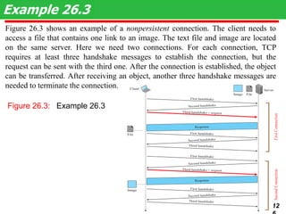
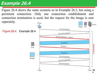
20CS2007
Computer Communication
Networks
Module 6
Transport and Application Protocols Browsing E-commerce website, Remote
access to server from workstation, Chat application. Process-to-process
delivery, UDP, TCP, Mobile Transport Protocols, Congestion control, DNS,
TELNET, HTTP.
Dr.A.Kathirvel, Professor,
DCSE, KITS
kathirvel@karunya.edu
23-1 PROCESS-TO-PROCESS DELIVERY
The transport layer is responsible for process-to-
process delivery—the delivery of a packet, part of a
message, from one process to another. Two processes
communicate in a client/server relationship, as we will
see later.
Client/Server Paradigm
Multiplexing and Demultiplexing
Connectionless Versus Connection-Oriented Service
Reliable Versus Unreliable
Three Protocols
Topics discussed in this section:
2
The transport layer is responsible for
process-to-process delivery.
Note
3
Figure 23.1 Types of data deliveries
Figure 23.2 Port numbers
Figure 23.4 IANA ranges
4
Figure 23.3 IP addresses versus port numbers
5
Figure 23.6 Multiplexing and demultiplexing
Figure 23.5 Socket address
Figure 23.7 Error control
6
Figure 23.8 Position of UDP, TCP, and SCTP in TCP/IP suite
7
23-2 USER DATAGRAM PROTOCOL (UDP)
The User Datagram Protocol (UDP) is called a
connectionless, unreliable transport protocol. It does
not add anything to the services of IP except to provide
process-to-process communication instead of host-to-
host communication.
Well-Known Ports for UDP
User Datagram
Checksum
UDP Operation
Use of UDP
Topics discussed in this section:
8
Table 23.1 Well-known ports used with UDP
9
In UNIX, the well-known ports are stored in a file called
/etc/services. Each line in this file gives the name of the server and
the well-known port number. We can use the grep utility to extract
the line corresponding to the desired application. The following
shows the port for FTP. Note that FTP can use port 21 with either
UDP or TCP.
Example 23.1
10
SNMP uses two port numbers 161&162, each for a different purpose.
Figure 23.9 User datagram format
UDP length
= IP length – IP header’s length
Note
11
Figure 23.10 Pseudoheader for checksum calculation
12
Figure shows the checksum calculation for a very small user datagram
with only 7 bytes of data. Because the number of bytes of data is odd,
padding is added for checksum calculation. The pseudoheader as well
as the padding will be dropped when the user datagram is delivered to
IP.
Example 23.2
13
Figure Checksum calculation of a simple UDP user datagram
Figure 23.12 Queues in UDP
14
23-3 TCP
TCP is a connection-oriented protocol; it creates a
virtual connection between two TCPs to send data. In
addition, TCP uses flow and error control mechanisms
at the transport level.
TCP Services
TCP Features
Segment
A TCP Connection
Flow Control
Error Control
Topics discussed in this section:
15
Table 23.2 Well-known ports used by TCP
16
Figure 23.13 Stream delivery
17
The bytes of data being transferred in each
connection are numbered by TCP. The numbering
starts with a randomly generated number.
Note
Figure 23.14 Sending and receiving buffers
18
Figure 23.15 TCP segments
19
The following shows the sequence number for
each segment:
Example 23.3
20
The value in the sequence number field
of a segment defines the number of the
first data byte contained in that segment.
Note
Figure 23.16 TCP segment format
The value of the acknowledgment field in a segment
defines the number of the next byte a party expects
to receive.The acknowledgment no. is cumulative.
Note
21
Figure 23.17 Control field
22
Figure 23.18 Connection establishment using three-way handshaking
Note
A SYN segment cannot carry data,
but it consumes one seq. no.
A SYN+ACK segment cannot carry
data, but does consume one seq. no.
An ACK segment, if carrying no data,
consumes no seq. no.
23
Figure 23.19 Data transfer
24
The FIN segment consumes
one sequence number if it
does not carry data.
Note
The FIN + ACK segment
consumes one sequence
number if it does not carry
data.
Figure 23.20 Connection termination using three-way handshaking
25
Figure 23.21 Half-close Figure 23.22 Sliding window
A sliding window is used to make
transmission more efficient as
well as to control the flow of data
so that the destination does not
become overwhelmed with data.
TCP sliding windows are byte-
oriented.
Note
26
Solution
The value of rwnd = 5000 − 1000 = 4000. Host B can receive only
4000 bytes of data before overflowing its buffer. Host B advertises this
value in its next segment to A.
What is the value of the receiver window (rwnd) for host A if
the receiver, host B, has a buffer size of 5000 bytes and 1000
bytes of received and unprocessed data?
Example 23.4
27
Example 23.5 : What is the size of the window for host A if the
value of rwnd is 3000 bytes and the value of cwnd is 3500 bytes?
Solution
The size of the window is the smaller of rwnd and cwnd, which is
3000 bytes.
reality this value is thousands of bytes). The receiver has sent an
acknowledgment number of 200 with an rwnd of 9 bytes (in reality this
value is thousands of bytes). The size of the sender window is the
minimum of rwnd and cwnd, or 9 bytes. Bytes 200 to 202 are sent, but
not acknowledged. Bytes 203 to 208 can be sent without worrying
about acknowledgment. Bytes 209 and above cannot be sent.
Example 23.6
Figure shows an unrealistic example of a sliding window. The
sender has sent bytes up to 202. We assume that cwnd is 20 (in
28
Some points about TCP sliding windows:
❏ The size of the window is the lesser of rwnd and
cwnd.
❏ The source does not have to send a full window’s
worth of data.
❏ The window can be opened or closed by the
receiver, but should not be shrunk.
❏ The destination can send an acknowledgment at
any time as long as it does not result in a shrinking
window.
❏ The receiver can temporarily shut down the
window; the sender, however, can always send a
segment of 1 byte after the window is shut down.
Note
29
ACK segments do not consume sequence numbers
and are not acknowledged.
Note
In modern implementations, a retransmission occurs if the
retransmission timer expires or three duplicate ACK
segments have arrived.
No retransmission timer is set for an ACK segment.
Data may arrive out of order and be temporarily stored by
the receiving TCP, but TCP guarantees that no out-of-order
segment is delivered to the process.
30
Figure 23.24 Normal operation
31
Figure 23.25 Lost segment
32
Figure 23.26 Fast retransmission
The receiver TCP
delivers only
ordered data to
the process.
Note
33
23-4 SCTP
Stream Control Transmission Protocol (SCTP) is a
new reliable, message-oriented transport layer
protocol. SCTP, however, is mostly designed for
Internet applications that have recently been
introduced. These new applications need a more
sophisticated service than TCP can provide.
SCTP Services and Features
Packet Format
An SCTPAssociation
Flow Control and Error Control
Topics discussed in this section:
34
Table 23.4 Some SCTP applications
SCTP is a message-oriented, reliable protocol that
combines the best features of UDP and TCP.
Note
35
Figure 23.27 Multiple-stream concept
An association in SCTP can involve
multiple streams.
Note
36
Figure 23.28 Multihoming concept
SCTP association allows multiple IP
addresses for each end.
Note
37
In SCTP, a data chunk is numbered using a TSN.
Note
38
To distinguish between different streams, SCTP uses an SI.
To distinguish between different data chunks belonging to
the same stream, SCTP uses SSNs.
TCP has segments; SCTP has packets.
Figure 23.29 Comparison between a TCP segment and an SCTP packet
39
In SCTP, control information and data
information are carried in separate chunks.
Note
Figure 23.30 Packet, data chunks, and streams
Data chunks are identified by three items: TSN, SI, and SSN.
TSN is a cumulative number identifying the association; SI
defines the stream; SSN defines the chunk in a stream.
Note
40
Figure 23.31 SCTP packet format
In SCTP, acknowledgment numbers are used to acknowledge only data
chunks; control chunks are ack. by other control chunks if necessary.
Note
In an SCTP packet, control chunks come before data chunks.
41
Figure 23.32 General header Figure 23.33 Four-way handshaking
42
Table 23.5 Chunks
43
A connection in SCTP is called an association.
Note
No other chunk is allowed in a packet carrying an INIT or
INIT ACK chunk. A COOKIE ECHO or a COOKIE ACK chunk
can carry data chunks.
In SCTP, only DATA chunks consume TSNs; DATA chunks
are the only chunks that are acknowledged.
44
Figure 23.34 Simple data transfer
The
acknowledgment
in SCTP defines
the cumulative
TSN, the TSN of
the last data
chunk received in
order.
Note
45
Figure 23.35 Association termination
46
Figure 23.36 Flow control, receiver site
Figure 23.37 Flow control, sender site
47
Figure 23.38 Flow control scenario
48
Figure 23.39 Error control, receiver site
49
Figure 23.40 Error control, sender site
50
What Is Congestion?
 Congestion occurs when the number of
packets being transmitted through the
network approaches the packet handling
capacity of the network
 Congestion control aims to keep number
of packets below level at which
performance falls off dramatically
 Data network is a network of queues
 Generally 80% utilization is critical
 Finite queues mean data may be lost
Queues at a Node
Effects of Congestion
 Packets arriving are stored at input buffers
 Routing decision made
 Packet moves to output buffer
 Packets queued for output transmitted as fast as
possible
 Statistical time division multiplexing
 If packets arrive to fast to be routed, or to be output,
buffers will fill
 Can discard packets
 Can use flow control
 Can propagate congestion through network
Interaction of Queues
Ideal
Network
Utilization
Practical Performance
 Ideal assumes infinite buffers and no
overhead
 Buffers are finite
 Overheads occur in exchanging congestion
control messages
Effects of
Congestion -
No Control
Mechanisms for
Congestion Control
Backpressure
 If node becomes congested it can slow down or halt flow
of packets from other nodes
 May mean that other nodes have to apply control on
incoming packet rates
 Propagates back to source
 Can restrict to logical connections generating most traffic
 Used in connection oriented that allow hop by hop
congestion control (e.g. X.25)
 Not used in ATM nor frame relay
 Only recently developed for IP
Choke Packet
 Control packet
 Generated at congested node
 Sent to source node
 e.g. ICMP source quench
 From router or destination
 Source cuts back until no more source quench
message
 Sent for every discarded packet, or anticipated
 Rather crude mechanism
Implicit Congestion Signaling
 Transmission delay may increase with
congestion
 Packet may be discarded
 Source can detect these as implicit
indications of congestion
 Useful on connectionless (datagram)
networks
 e.g. IP based
 (TCP includes congestion and flow control - see
chapter 17)
Explicit Congestion Signaling
 Network alerts end systems of increasing
congestion
 End systems take steps to reduce offered
load
 Backwards
 Congestion avoidance in opposite direction to
packet required
 Forwards
 Congestion avoidance in same direction as
packet required
Categories of Explicit Signaling
 Binary
 A bit set in a packet indicates congestion
 Credit based
 Indicates how many packets source may send
 Common for end to end flow control
 Rate based
 Supply explicit data rate limit
 e.g. ATM
Traffic Management
 Fairness
 Quality of service
 May want different treatment for different
connections
 Reservations
 e.g. ATM
 Traffic contract between user and network
Congestion Control in Packet
Switched Networks
 Send control packet to some or all source
nodes
 Requires additional traffic during congestion
 Rely on routing information
 May react too quickly
 End to end probe packets
 Adds to overhead
 Add congestion info to packets as they
cross nodes
 Either backwards or forwards
Frame Relay
Congestion Control
 Minimize discards
 Maintain agreed QoS
 Minimize probability of one end user monoply
 Simple to implement
 Little overhead on network or user
 Create minimal additional traffic
 Distribute resources fairly
 Limit spread of congestion
 Operate effectively regardless of traffic flow
 Minimum impact on other systems
 Minimize variance in QoS
Techniques
 Discard strategy
 Congestion avoidance
 Explicit signaling
 Congestion recovery
 Implicit signaling mechanism
Traffic Rate Management
 Must discard frames to cope with
congestion
 Arbitrarily, no regard for source
 No reward for restraint so end systems
transmit as fast as possible
 Committed information rate (CIR)
 Data in excess of this liable to discard
 Not guaranteed
 Aggregate CIR should not exceed physical data
rate
 Committed burst size
Operation of CIR
Relationship
Among
Congestion
Parameters
Explicit Signaling
 Network alerts end systems of growing
congestion
 Backward explicit congestion notification
 Forward explicit congestion notification
 Frame handler monitors its queues
 May notify some or all logical connections
 User response
 Reduce rate
ATM Traffic Management
 High speed, small cell size, limited
overhead bits
 Still evolving
 Requirements
 Majority of traffic not amenable to flow
control
 Feedback slow due to reduced transmission
time compared with propagation delay
 Wide range of application demands
 Different traffic patterns
 Different network services
Latency/Speed Effects
 ATM 150Mbps
 ~2.8x10⁻⁶ seconds to insert single cell
 Time to traverse network depends on propagation delay,
switching delay
 Assume propagation at two-thirds speed of light
 If source and destination on opposite sides of USA,
propagation time ~ 48x10-3 seconds
 Given implicit congestion control, by the time dropped
cell notification has reached source, 7.2x106 bits have
been transmitted
 So, this is not a good strategy for ATM
Cell Delay Variation
 For ATM voice/video, data is a stream of
cells
 Delay across network must be short
 Rate of delivery must be constant
 There will always be some variation in
transit
 Delay cell delivery to application so that
constant bit rate can be maintained to
application
Time Re-assembly of CBR Cells
Network Contribution to
Cell Delay Variation
 Packet switched networks
 Queuing delays
 Routing decision time
 Frame relay
 As above but to lesser extent
 ATM
 Less than frame relay
 ATM protocol designed to minimize processing overheads at
switches
 ATM switches have very high throughput
 Only noticeable delay is from congestion
 Must not accept load that causes congestion
Cell Delay Variation
At The UNI
 Application produces data at fixed rate
 Processing at three layers of ATM causes
delay
 Interleaving cells from different connections
 Operation and maintenance cell interleaving
 If using synchronous digital hierarchy frames,
these are inserted at physical layer
 Can not predict these delays
Origins of Cell Delay Variation
Traffic and Congestion
Control Framework
 ATM layer traffic and congestion control
should support QoS classes for all
foreseeable network services
 Should not rely on AAL protocols that are
network specific, nor higher level
application specific protocols
 Should minimize network and end to end
system complexity
Timings Considered
 Cell insertion time
 Round trip propagation time
 Connection duration
 Long term
 Determine whether a given new
connection can be accommodated
 Agree performance parameters with
subscriber
Traffic Management and
Congestion Control Techniques
 Resource management using virtual paths
 Connection admission control
 Usage parameter control
 Selective cell discard
 Traffic shaping
Resource Management Using
Virtual Paths
 Separate traffic flow according to service
characteristics
 User to user application
 User to network application
 Network to network application
 Concern with:
 Cell loss ratio
 Cell transfer delay
 Cell delay variation
Configuration of
VCCs and VPCs
Allocating VCCs within VPC
 All VCCs within VPC should experience
similar network performance
 Options for allocation:
 Aggregate peak demand
 Statistical multiplexing
Connection Admission Control
 First line of defense
 User specifies traffic characteristics for
new connection (VCC or VPC) by selecting
a QoS
 Network accepts connection only if it can
meet the demand
 Traffic contract
 Peak cell rate
 Cell delay variation
 Sustainable cell rate
Usage Parameter Control
 Monitor connection to ensure traffic
cinforms to contract
 Protection of network resources from
overload by one connection
 Done on VCC and VPC
 Peak cell rate and cell delay variation
 Sustainable cell rate and burst tolerance
 Discard cells that do not conform to traffic
contract
 Called traffic policing
Traffic Shaping
 Smooth out traffic flow and reduce cell
clumping
 Token bucket
Token Bucket for
Traffic Shaping
GFR Traffic Management
 Guaranteed frame rate is as simple as UBR
from end system viewpoint
 Places modest requirements on ATM
network elements
 End system does no policing or shaping of
traffic
 May transmit at line rate of ATM adaptor
 No guarantee of delivery
 Higher layer (e.g. TCP) must do congestion
control
 User can reserve capacity for each VC
Frame Recognition
 GFR recognizes frames as well as cells
 When congested, network discards whole
frame rather than individual cells
 All cells of a frame have same CLP bit
setting
 CLP=1 AAL5 frames are lower priority
 Best efforts
 CLP=0 frames minimum guaranteed
capacity
GFR Contract Parameters
 Peak cell rate (PCR)
 Minimum cell rate (MCR)
 Maximum burst size (MBS)
 Maximum frame size (MFS)
 Cell delay variation tolerance (CDVT)
Mechanisms for Supporting Rate
Guarantees (1)
 Tagging and policing
 Discriminate between frames that conform to contract and those
that don’t
 Set CLP=1 on all cells in frame if not
 Gives lower priority
 Maybe done by network or source
 Network may discard CLP=1 cells
 Policing
 Buffer management
 Treatment of buffered cells
 Congestion indicated by high buffer occupancy
 Discard tagged cells
 Including ones already in buffer to make room
 To be fair, per VC buffering
 Cell discard based on queue-specific thresholds
Mechanisms for Supporting Rate
Guarantees (2)
 Scheduling
 Give preferential treatment to untagged cells
 Separate queues for each VC
 Make per-VC scheduling decisions
 Enables control of outgoing rate of VCs
 VCs get fair capacity allocation
 Still meet contract
Components of GFR System
Conformance Definition
 UPC
 Monitors each active VC
 Ensure traffic conforms to contract
 Tag or discard nonconforming cells
 Frame conforms if all cells conform
 Cell conforms if:
 Rate of cells within contract
 All cells in frame have same CLP
 Frame satisfies MFS parameter (check for last cell
in frame or cell count < MFS)
QoS Eligibility Test
 Two stage filtering process
 Frame tested for conformance to contract
 If not, may discard
 If not discarded, tag
 Sets upper bound
 Penalize cells above upper bound
 Implementations expected to attempt delivery of
tagged cells
 Determine frames eligible for QoS guarantees
 Under GFR contract for VC
 Lower bound on traffic
GFR VC Frame Categories
 Nonconforming frame
 Cells of this frame will be tagged or discarded
 Conforming but ineligible frames
 Cells will receive a best-effort service
 Conforming and eligible frames
 Cells will receive a guarantee of delivery
DNS : Domain Name System
 To map a hostname to an IP-address and vice
versa.
Example:
www.acad.bg 194.141.0.9
 Each hostname may has zero or more corresponding IP-
addresses.
 Each IP-address may correspond to zero or more
hostnames.
98
DNS
 Host name to address mappings were maintained by the Network
Information Center (NIC) in a single file (HOSTS.TXT) which was
transferred to all hosts using FTP (about 25 years ago).
Disadvantages:
 Ineffective – Bandwidth consumed in distributing a new version by
this scheme is proportional to the square of the number of hosts in the
network.
 The network population was also changing in character.
 The applications on the Internet were getting more sophisticated and
creating a need for general purpose name service.
99
DNS design goals
The primary goal is a consistent name space which will be
used for referring to resources.
The database which holds the names must be distributed.
The costs of implementing such a facility dictate that it be
generally useful, and not restricted to a single application.
Use the same name space with different protocol families
or management.
Name server transactions must be independent of the
communications system that carries them.
The system should be useful across a wide spectrum of
host capabilities. Both personal computers and large
timeshared hosts (mainframes) should be able to use the
system, though perhaps in different ways. 10
0
DNS Elements: 3 main components
1. The DOMAIN NAME SPACE and RESOURCE RECORDS,
which are specifications for a tree structured name space and data
associated with the names.
2. NAME SERVERS are server programs which hold information
about the domain tree's structure and set information.
3. RESOLVERS are programs that extract information from name
servers in response to client requests.
These three components roughly correspond to the three layers or
views of the DNS:
 From the user's point of view, the domain system is accessed through
a simple procedure.
 From the resolver's point of view, the domain system is composed of
an unknown number of name servers.
 From a name server's point of view, the domain system consists of
separate sets of local information called zones.
10
1
Name space specifications and terminology
 The domain name space is a tree structure composed by nodes.
 Each node has a label, which is zero to 63 octets in length.
 The domain name of a node is the list of the labels on the path from
the node to the root of the tree.
 The name of the root node is empty string (zero length) – “”.
 Internally, programs that manipulate domain names should represent
them as sequences of labels, where each label is a length octet
followed by an octet string.
 Domain names are case-insensitive using the ASCII codes with high
order zero bit.
 When a user types a domain name, the length of each label is omitted
and the labels are separated by dots ("."). Since a complete domain
name ends with the root label, this leads to a printed form which ends
in a dot.
10
2
Example Name Space
(a graphical tree view)
com edu bg eu info
ucla
physics
yahoo
joe
acad
amigo val
see-
grid
www
kevin
mary
Top Level Domains (TLD)
One Root domain (“”)
test
sigma
book
mail
Delegation
2nd Level Domains
Up to 127 levels
3
rd Level Domains
ICANN, IANA
10
3
Top Level Domains
 Generic domains (gTLD): com, org, net, int (all around the world);
edu, gov, mil (located in USA only); aero, biz, coop, info,
museum, name, pro(new domains,since 2000)
 Country code domains (ccTLD): bg, uk, fr, it, ...
 Special infrastructure domain: arpa
 Loopback domains: localhost, localdomain
 And the domain eu for European Union!
Resource
Records
 The distributed database which holds the
names consists of several Resource Records.
 Resource record - Set of resource information
associated with a particular name.
10
4
DNS server
A computer with software which:
 Holds and maintains specified part of the distributed database of
resource records.
 Responds to the name queries.
 Exchanges the zone information with other DNS servers.
These tasks are described in the DNS protocol (RFC 1035) located on
the Application Layer of the “TCP/IP reference model”.
Delegation:
 ICANN organization delegates root DNS servers.
 The root servers delegate TLD DNS servers.
 A TLD DNS server delegates Second Level DNS server etc. 10
5
The root DNS servers
At the heart of the DNS are 13 special computers, called root
servers. They are coordinated by ICANN and are distributed
around the world.
A.ROOT-SERVERS.NET. 198.41.0.4
B.ROOT-SERVERS.NET. 192.228.79.201
C.ROOT-SERVERS.NET. 192.33.4.12
D.ROOT-SERVERS.NET. 128.8.10.90
E.ROOT-SERVERS.NET. 192.203.230.10
F.ROOT-SERVERS.NET. 192.5.5.241
G.ROOT-SERVERS.NET. 192.112.36.4
H.ROOT-SERVERS.NET. 128.63.2.53
I.ROOT-SERVERS.NET. 192.36.148.17
J.ROOT-SERVERS.NET. 192.58.128.30
K.ROOT-SERVERS.NET. 193.0.14.129
L.ROOT-SERVERS.NET. 199.7.83.42
M.ROOT-SERVERS.NET. 202.12.27.33
10
6
K.ROOT-SERVERS.NET
(operated by RIPE NCC)
Source: http://k.root-servers.org 10
7
DNS servers
Primary DNS server for a given domain – holds resource records for the zone.
The zone configuration is written by the system administrator.
Secondary DNS server for a given domain – it exists for the case when the
Primary DNS server is failed or overloaded. The Secondary server
downloads the zone information from the Primary periodically or by
notification.
 Every domain must have one Primary DNS server and at least one
Secondary.
The Primary and Secondary DNS servers are also called authoritative for
their domain and non-authoritative for the rest of domains in the world.
E.g. the authoritative servers always hold up to date zone information for
the domain.
 Caching only DNS servers – they cache DNS queries and answers for
speed-up the service. These servers are not authoritative for any domain.
Most of the authoritative DNS servers are caching too. 10
8
DNS query flow
1. A DNS client forms the query and sends it according the OS configuration.
2. The local resolver opens a special file called hosts and looks in case the
answer is already written here. If not then next:
3. The client calls one of the OS configured DNS servers.
4. If the DNS server knows (or already cached) the answer, then returns it.
5. If the DNS server doesn’t know the answer, it sends a recursive query
through the DNS hierarchy, starting from the root domain. The recursive
query consists of several sub-queries to the corresponding DNS servers.
6. The DNS servers returns the result – the answer or error message.
10
9
Reverse DNS query
 The reverse query uses the special infrastructure domain in-
addr.arpa
 The IP is written before this special domain in reverse order of
numbers separated with dots.
 Example: 194.141.0.0 corresponds to 0.0.141.194.in-
addr.arpa
 The reverse query starts from a root DNS server and follows the
delegation path.
 Example in Unix/Linux:dig 0.0.141.194.in-addr.arpa +trace
 (It traces and shows the delegation path from the root name
servers down to SOA DNS server)
11
0
DNS protocol details
 The protocol uses two transport protocols from the lower layer:
 UDP on port 53 and
 TCP on port 53.
 The queries and answers are transferred using the unreliable protocol
UDP for speed. But it is preferred because the OS configured DNS
servers are near, usually in the same LAN.
 The zone transfers between the DNS servers are performed through
TCP, because it must be reliable.
 Each resource record consists of the following data fields
( in text readable format! ): owner type class TTL RDATA
11
1
Resource Records
The data fields
owner - A string which is the domain name where the RR is found.
type - which is an encoded 16 bit value that specifies the type of the resource in this
resource record. Types refer to abstract resources. Each abstract resource has memo
name:
A - a host address
CNAME - identifies the canonical name of an alias
MX - identifies a mail exchange for the domain
PTR - a pointer to another part of the domain name space etc.
class - which is an encoded 16 bit value which identifies a protocol family or instance
of a protocol. This memo uses the following classes:
IN - the Internet system or CH - the Chaos system
TTL - which is the time to live of the RR. This field is a 32 bit integer in units of
seconds, an is primarily used by resolvers when they cache RRs. The TTL describes
how long a RR can be cached before it should be discarded.
RDATA - which is the type and sometimes class dependent data which describes the
resource.
11
2
Resource Records
Example
(in text readable format!)
acad.bg. IN A 194.141.0.9
acad.bg. IN MX 10 mx-a.acad.bg.
IN MX 20 mx-b.acad.bg.
IN NS amigo.acad.bg.
IN NS unicom.acad.bg.
localhost IN A 127.0.0.1
poseidon IN A 194.141.0.1
backbone IN A 194.141.252.2
iris IN A 194.141.0.2
amigo IN AAAA 2001:4b58:acad::3
unicom IN AAAA 2001:4b58:acad::9
bis-21++ IN CNAME unicom.acad.bg.
3 IN PTR amigo.acad.bg.
...
11
3
DNS protocol details
Message in binary format
(RR means Resource Record)
11
4
DNS protocol details
DNS message data fields
 The IDENTIFICATION field is set by the client and returned by the server.
 The 16-bit PARAMETER consists of:
 0-th bit field: 0 means the message is a query,1 means it's a response.
 1-4 bit fields - OPCODE:
 0000 - is a normal value (Standard query).
 0001 - an inverse query.
 0010 - the server status request.
 5-th bit field - Authoritative answer. The name server is authoritative for the
domain in the question section.
 6-th bit field is set if message truncated. With UDP this means that the total size
of the reply exceeded 512 bytes, and only the first 512 bytes the of the reply
were returned.
 7-th bit field - Recursion Desired. This bit can be set in a query and is then
returned in the response.
 8-th bit field - Recursion Available.
 9-11 -th bits field has to be 0.
 12-15 -th bits field - Return Code. 0- no error, 3- name error.
115
11
5
DNS protocol details
DNS message data fields
 The fields labeled NUMBER OF ... give each a count of entries in the
corresponding sections in the message.
 The QUESTION SECTION contains queries for which answers are
desired. The client fills in only the question section; the server returns
the question and answers with its response. Each question has Query
Domain Name followed by Query Type and Query Class fields (as
depicted in the next slides)
 ANSWER,AUTHORITY,ADDITIONAL INFORMATION sections
consist of a set of resource records that describe domain names and
mappings. Each resource record describes one name (as depicted in
the next slides)
11
6
DNS protocol details
The QUESTION section format in the DNS message
The DOMAIN NAME has variable length.
Clients fill in the questions; servers return them along with the answers.
11
7
DNS protocol details
The RESOURCE RECORD binary format returned by the DNS
servers
11
8
26-4 TELNET
It is impossible to have a client/server pair for each type of
service we need; the number of servers soon becomes
intractable. The idea is not scalable. The solution is to have a
specific client/server program for a set of common scenarios, but
to have some generic client/server programs for the rest.
11
9
Trivial FTP (TFTP)
A very simple file transfer protocol, with the functionality of a very basic
form of FTP. Defined in 1980.
TFTP uses UDP port 69 (not TCP!)
An ex. of TFTP usage for remote boot through BOOTP protocol in a LAN:
12
0
FTP pros and cons
 Advantages:
 Simple implementation
 Universal application
 Wide used and standartized
 Disadvantages:
 Clear text passwords, unencrypted data.
 Multiple TCP/IP connections are used = > Firewalls problems.
 Hard to filter active mode FTP traffic on the client side by using a
firewall.
 It is possible to abuse the protocol's built-in proxy features to tell a server
to send data to an arbitrary port of a third computer;
 High latency.
 No integrity check on the receiver side.
 No date/timestamp attribute transfer.
12
1
26.4.1 Local versus Remote Logging
We first discuss the concept of local and remote logging as
shown in Figure 26.23.
Figure 26.23: Local versus remote logging
12
2
Figure 26.24: Concept of NVT
Table 26.11: Examples of interface commands
12
3
26.26.2 HyperText Transfer Protocol
The HyperText Transfer Protocol (HTTP) is used to
define how the client-server programs can be written
to retrieve web pages from the Web. An HTTP client
sends a request; an HTTP server returns a response.
The server uses the port number 80; the client uses a
temporary port number. HTTP uses the services of
TCP, which, as discussed before, is a connection-
oriented and reliable protocol.
12
The World Wide Web - HTTP
 Hypertext Transfer Protocol (HTTP) is a
communications protocol used to transfer or convey
information on intranets and the World Wide Web. Its
original purpose was to provide a way to publish and
retrieve hypertext pages, mainly scientific paper. Created in
CERN, Geneva.
 Development of HTTP was coordinated by the W3C
(World Wide Web Consortium) and the IETF (Internet
Engineering Task Force), culminating in the publication of a
series of RFCs, most notably
RFC 2616 (June 1999), which defines HTTP/1.1, the
current version.
 HTTP is a request/response protocol between a client and
a server. It works on the well known TCP port 80.
12
Figure 26.3 shows an example of a nonpersistent connection. The client needs to
access a file that contains one link to an image. The text file and image are located
on the same server. Here we need two connections. For each connection, TCP
requires at least three handshake messages to establish the connection, but the
request can be sent with the third one. After the connection is established, the object
can be transferred. After receiving an object, another three handshake messages are
needed to terminate the connection.
Example 26.3
12
Figure 26.3: Example 26.3
Figure 26.4 shows the same scenario as in Example 26.3, but using a
persistent connection. Only one connection establishment and
connection termination is used, but the request for the image is sent
separately.
Example 26.4
12
Figure 26.4: Example 26.4
Figure 26.5: Formats of the request and response messages
12
Table 26.1: Methods
12
Table 26.2: Request Header Names
13
Table 26.3: Response Header Names
13
This example retrieves a document (see Figure 26.6). We use the GET method to
retrieve an image with the path /usr/bin/image26. The request line shows the method
(GET), the URL, and the HTTP version (26.1). The header has two lines that show that
the client can accept images in the GIF or JPEG format. The request does not have a
body. The response message contains the status line and four lines of header. The
header lines define the date, server, content encoding (MIME version, which will be
described in electronic mail), and length of the document. The body of the document
follows the header..
Example 26.5
13
Figure 26.6:
Example 26.5
In this example, the client wants to send a web page to be posted on the server.
We use the PUT method. The request line shows the method (PUT), URL, and
HTTP version (26.1). There are four lines of headers. The request body
contains the web page to be posted. The response message contains the status
line and four lines of headers. The created document, which is a CGI
document, is included as the body (see Figure 26.7).
Example 26.6
Figure 26.7:
Example 26.6
13
3
Figure 26.8 shows a scenario in which an electronic store
can benefit from the use of cookies. Assume a shopper
wants to buy a toy from an electronic store named BestToys.
The shopper browser (client) sends a request to the BestToys
server. The server creates an empty shopping cart (a list) for
the client and assigns an ID to the cart (for example, 12343).
The server then sends a response message, which contains
the images of all toys available, with a link under each toy
that selects the toy if it is being clicked. This response
message also includes the Set-Cookie header line whose
value is 12343. The client displays the images and stores the
cookie value in a file named BestToys.
Example 26.8
13
5
Figure 26.8: Example 26.8
13
Figure 26.9 shows an example of a use of a proxy server in a local network, such as
the network on a campus or in a company. The proxy server is installed in the local
network. When an HTTP request is created by any of the clients (browsers), the
request is first directed to the proxy server If the proxy server already has the
corresponding web page, it sends the response to the client. Otherwise, the proxy
server acts as a client and sends the request to the web server in the Internet. When
the response is returned, the proxy server makes a copy and stores it in its cache
before sending it to the requesting client.
Example 26.9
13
Figure 26.9: Example
of a proxy server
HTML – HyperText Markup Language
 In 1980, physicist Tim Berners-Lee, who was an
independent contractor at CERN, proposed and
prototyped ENQUIRE, a hypertext system for CERN
researchers to use to share documents.
 In 1989, Berners-Lee and CERN data systems
engineer Robert Cailliau each submitted separate
proposals for an Internet-based hypertext system
providing similar functionality.
 In 1990, they collaborated on a joint proposal, the
World Wide Web (W3) project, which was accepted
by CERN.
13
HTML
A selection of common HTML tags. some can have additional
parameters (attributes).
13
Questions?

20CS2007 Computer Communication Networks

  • 1.
    20CS2007 Computer Communication Networks Module 6 Transportand Application Protocols Browsing E-commerce website, Remote access to server from workstation, Chat application. Process-to-process delivery, UDP, TCP, Mobile Transport Protocols, Congestion control, DNS, TELNET, HTTP. Dr.A.Kathirvel, Professor, DCSE, KITS kathirvel@karunya.edu
  • 2.
    23-1 PROCESS-TO-PROCESS DELIVERY Thetransport layer is responsible for process-to- process delivery—the delivery of a packet, part of a message, from one process to another. Two processes communicate in a client/server relationship, as we will see later. Client/Server Paradigm Multiplexing and Demultiplexing Connectionless Versus Connection-Oriented Service Reliable Versus Unreliable Three Protocols Topics discussed in this section: 2
  • 3.
    The transport layeris responsible for process-to-process delivery. Note 3 Figure 23.1 Types of data deliveries
  • 4.
    Figure 23.2 Portnumbers Figure 23.4 IANA ranges 4
  • 5.
    Figure 23.3 IPaddresses versus port numbers 5 Figure 23.6 Multiplexing and demultiplexing Figure 23.5 Socket address
  • 6.
  • 7.
    Figure 23.8 Positionof UDP, TCP, and SCTP in TCP/IP suite 7
  • 8.
    23-2 USER DATAGRAMPROTOCOL (UDP) The User Datagram Protocol (UDP) is called a connectionless, unreliable transport protocol. It does not add anything to the services of IP except to provide process-to-process communication instead of host-to- host communication. Well-Known Ports for UDP User Datagram Checksum UDP Operation Use of UDP Topics discussed in this section: 8
  • 9.
    Table 23.1 Well-knownports used with UDP 9
  • 10.
    In UNIX, thewell-known ports are stored in a file called /etc/services. Each line in this file gives the name of the server and the well-known port number. We can use the grep utility to extract the line corresponding to the desired application. The following shows the port for FTP. Note that FTP can use port 21 with either UDP or TCP. Example 23.1 10 SNMP uses two port numbers 161&162, each for a different purpose.
  • 11.
    Figure 23.9 Userdatagram format UDP length = IP length – IP header’s length Note 11
  • 12.
    Figure 23.10 Pseudoheaderfor checksum calculation 12
  • 13.
    Figure shows thechecksum calculation for a very small user datagram with only 7 bytes of data. Because the number of bytes of data is odd, padding is added for checksum calculation. The pseudoheader as well as the padding will be dropped when the user datagram is delivered to IP. Example 23.2 13 Figure Checksum calculation of a simple UDP user datagram
  • 14.
  • 15.
    23-3 TCP TCP isa connection-oriented protocol; it creates a virtual connection between two TCPs to send data. In addition, TCP uses flow and error control mechanisms at the transport level. TCP Services TCP Features Segment A TCP Connection Flow Control Error Control Topics discussed in this section: 15
  • 16.
    Table 23.2 Well-knownports used by TCP 16
  • 17.
    Figure 23.13 Streamdelivery 17 The bytes of data being transferred in each connection are numbered by TCP. The numbering starts with a randomly generated number. Note
  • 18.
    Figure 23.14 Sendingand receiving buffers 18
  • 19.
    Figure 23.15 TCPsegments 19
  • 20.
    The following showsthe sequence number for each segment: Example 23.3 20 The value in the sequence number field of a segment defines the number of the first data byte contained in that segment. Note
  • 21.
    Figure 23.16 TCPsegment format The value of the acknowledgment field in a segment defines the number of the next byte a party expects to receive.The acknowledgment no. is cumulative. Note 21
  • 22.
  • 23.
    Figure 23.18 Connectionestablishment using three-way handshaking Note A SYN segment cannot carry data, but it consumes one seq. no. A SYN+ACK segment cannot carry data, but does consume one seq. no. An ACK segment, if carrying no data, consumes no seq. no. 23
  • 24.
    Figure 23.19 Datatransfer 24 The FIN segment consumes one sequence number if it does not carry data. Note The FIN + ACK segment consumes one sequence number if it does not carry data.
  • 25.
    Figure 23.20 Connectiontermination using three-way handshaking 25
  • 26.
    Figure 23.21 Half-closeFigure 23.22 Sliding window A sliding window is used to make transmission more efficient as well as to control the flow of data so that the destination does not become overwhelmed with data. TCP sliding windows are byte- oriented. Note 26
  • 27.
    Solution The value ofrwnd = 5000 − 1000 = 4000. Host B can receive only 4000 bytes of data before overflowing its buffer. Host B advertises this value in its next segment to A. What is the value of the receiver window (rwnd) for host A if the receiver, host B, has a buffer size of 5000 bytes and 1000 bytes of received and unprocessed data? Example 23.4 27 Example 23.5 : What is the size of the window for host A if the value of rwnd is 3000 bytes and the value of cwnd is 3500 bytes? Solution The size of the window is the smaller of rwnd and cwnd, which is 3000 bytes.
  • 28.
    reality this valueis thousands of bytes). The receiver has sent an acknowledgment number of 200 with an rwnd of 9 bytes (in reality this value is thousands of bytes). The size of the sender window is the minimum of rwnd and cwnd, or 9 bytes. Bytes 200 to 202 are sent, but not acknowledged. Bytes 203 to 208 can be sent without worrying about acknowledgment. Bytes 209 and above cannot be sent. Example 23.6 Figure shows an unrealistic example of a sliding window. The sender has sent bytes up to 202. We assume that cwnd is 20 (in 28
  • 29.
    Some points aboutTCP sliding windows: ❏ The size of the window is the lesser of rwnd and cwnd. ❏ The source does not have to send a full window’s worth of data. ❏ The window can be opened or closed by the receiver, but should not be shrunk. ❏ The destination can send an acknowledgment at any time as long as it does not result in a shrinking window. ❏ The receiver can temporarily shut down the window; the sender, however, can always send a segment of 1 byte after the window is shut down. Note 29
  • 30.
    ACK segments donot consume sequence numbers and are not acknowledged. Note In modern implementations, a retransmission occurs if the retransmission timer expires or three duplicate ACK segments have arrived. No retransmission timer is set for an ACK segment. Data may arrive out of order and be temporarily stored by the receiving TCP, but TCP guarantees that no out-of-order segment is delivered to the process. 30
  • 31.
    Figure 23.24 Normaloperation 31
  • 32.
  • 33.
    Figure 23.26 Fastretransmission The receiver TCP delivers only ordered data to the process. Note 33
  • 34.
    23-4 SCTP Stream ControlTransmission Protocol (SCTP) is a new reliable, message-oriented transport layer protocol. SCTP, however, is mostly designed for Internet applications that have recently been introduced. These new applications need a more sophisticated service than TCP can provide. SCTP Services and Features Packet Format An SCTPAssociation Flow Control and Error Control Topics discussed in this section: 34
  • 35.
    Table 23.4 SomeSCTP applications SCTP is a message-oriented, reliable protocol that combines the best features of UDP and TCP. Note 35
  • 36.
    Figure 23.27 Multiple-streamconcept An association in SCTP can involve multiple streams. Note 36
  • 37.
    Figure 23.28 Multihomingconcept SCTP association allows multiple IP addresses for each end. Note 37
  • 38.
    In SCTP, adata chunk is numbered using a TSN. Note 38 To distinguish between different streams, SCTP uses an SI. To distinguish between different data chunks belonging to the same stream, SCTP uses SSNs. TCP has segments; SCTP has packets.
  • 39.
    Figure 23.29 Comparisonbetween a TCP segment and an SCTP packet 39 In SCTP, control information and data information are carried in separate chunks. Note
  • 40.
    Figure 23.30 Packet,data chunks, and streams Data chunks are identified by three items: TSN, SI, and SSN. TSN is a cumulative number identifying the association; SI defines the stream; SSN defines the chunk in a stream. Note 40
  • 41.
    Figure 23.31 SCTPpacket format In SCTP, acknowledgment numbers are used to acknowledge only data chunks; control chunks are ack. by other control chunks if necessary. Note In an SCTP packet, control chunks come before data chunks. 41
  • 42.
    Figure 23.32 Generalheader Figure 23.33 Four-way handshaking 42
  • 43.
  • 44.
    A connection inSCTP is called an association. Note No other chunk is allowed in a packet carrying an INIT or INIT ACK chunk. A COOKIE ECHO or a COOKIE ACK chunk can carry data chunks. In SCTP, only DATA chunks consume TSNs; DATA chunks are the only chunks that are acknowledged. 44
  • 45.
    Figure 23.34 Simpledata transfer The acknowledgment in SCTP defines the cumulative TSN, the TSN of the last data chunk received in order. Note 45
  • 46.
  • 47.
    Figure 23.36 Flowcontrol, receiver site Figure 23.37 Flow control, sender site 47
  • 48.
    Figure 23.38 Flowcontrol scenario 48
  • 49.
    Figure 23.39 Errorcontrol, receiver site 49
  • 50.
    Figure 23.40 Errorcontrol, sender site 50
  • 51.
    What Is Congestion? Congestion occurs when the number of packets being transmitted through the network approaches the packet handling capacity of the network  Congestion control aims to keep number of packets below level at which performance falls off dramatically  Data network is a network of queues  Generally 80% utilization is critical  Finite queues mean data may be lost
  • 52.
  • 53.
    Effects of Congestion Packets arriving are stored at input buffers  Routing decision made  Packet moves to output buffer  Packets queued for output transmitted as fast as possible  Statistical time division multiplexing  If packets arrive to fast to be routed, or to be output, buffers will fill  Can discard packets  Can use flow control  Can propagate congestion through network
  • 54.
  • 55.
  • 56.
    Practical Performance  Idealassumes infinite buffers and no overhead  Buffers are finite  Overheads occur in exchanging congestion control messages
  • 57.
  • 58.
  • 59.
    Backpressure  If nodebecomes congested it can slow down or halt flow of packets from other nodes  May mean that other nodes have to apply control on incoming packet rates  Propagates back to source  Can restrict to logical connections generating most traffic  Used in connection oriented that allow hop by hop congestion control (e.g. X.25)  Not used in ATM nor frame relay  Only recently developed for IP
  • 60.
    Choke Packet  Controlpacket  Generated at congested node  Sent to source node  e.g. ICMP source quench  From router or destination  Source cuts back until no more source quench message  Sent for every discarded packet, or anticipated  Rather crude mechanism
  • 61.
    Implicit Congestion Signaling Transmission delay may increase with congestion  Packet may be discarded  Source can detect these as implicit indications of congestion  Useful on connectionless (datagram) networks  e.g. IP based  (TCP includes congestion and flow control - see chapter 17)
  • 62.
    Explicit Congestion Signaling Network alerts end systems of increasing congestion  End systems take steps to reduce offered load  Backwards  Congestion avoidance in opposite direction to packet required  Forwards  Congestion avoidance in same direction as packet required
  • 63.
    Categories of ExplicitSignaling  Binary  A bit set in a packet indicates congestion  Credit based  Indicates how many packets source may send  Common for end to end flow control  Rate based  Supply explicit data rate limit  e.g. ATM
  • 64.
    Traffic Management  Fairness Quality of service  May want different treatment for different connections  Reservations  e.g. ATM  Traffic contract between user and network
  • 65.
    Congestion Control inPacket Switched Networks  Send control packet to some or all source nodes  Requires additional traffic during congestion  Rely on routing information  May react too quickly  End to end probe packets  Adds to overhead  Add congestion info to packets as they cross nodes  Either backwards or forwards
  • 66.
    Frame Relay Congestion Control Minimize discards  Maintain agreed QoS  Minimize probability of one end user monoply  Simple to implement  Little overhead on network or user  Create minimal additional traffic  Distribute resources fairly  Limit spread of congestion  Operate effectively regardless of traffic flow  Minimum impact on other systems  Minimize variance in QoS
  • 67.
    Techniques  Discard strategy Congestion avoidance  Explicit signaling  Congestion recovery  Implicit signaling mechanism
  • 68.
    Traffic Rate Management Must discard frames to cope with congestion  Arbitrarily, no regard for source  No reward for restraint so end systems transmit as fast as possible  Committed information rate (CIR)  Data in excess of this liable to discard  Not guaranteed  Aggregate CIR should not exceed physical data rate  Committed burst size
  • 69.
  • 70.
  • 71.
    Explicit Signaling  Networkalerts end systems of growing congestion  Backward explicit congestion notification  Forward explicit congestion notification  Frame handler monitors its queues  May notify some or all logical connections  User response  Reduce rate
  • 72.
    ATM Traffic Management High speed, small cell size, limited overhead bits  Still evolving  Requirements  Majority of traffic not amenable to flow control  Feedback slow due to reduced transmission time compared with propagation delay  Wide range of application demands  Different traffic patterns  Different network services
  • 73.
    Latency/Speed Effects  ATM150Mbps  ~2.8x10⁻⁶ seconds to insert single cell  Time to traverse network depends on propagation delay, switching delay  Assume propagation at two-thirds speed of light  If source and destination on opposite sides of USA, propagation time ~ 48x10-3 seconds  Given implicit congestion control, by the time dropped cell notification has reached source, 7.2x106 bits have been transmitted  So, this is not a good strategy for ATM
  • 74.
    Cell Delay Variation For ATM voice/video, data is a stream of cells  Delay across network must be short  Rate of delivery must be constant  There will always be some variation in transit  Delay cell delivery to application so that constant bit rate can be maintained to application
  • 75.
  • 76.
    Network Contribution to CellDelay Variation  Packet switched networks  Queuing delays  Routing decision time  Frame relay  As above but to lesser extent  ATM  Less than frame relay  ATM protocol designed to minimize processing overheads at switches  ATM switches have very high throughput  Only noticeable delay is from congestion  Must not accept load that causes congestion
  • 77.
    Cell Delay Variation AtThe UNI  Application produces data at fixed rate  Processing at three layers of ATM causes delay  Interleaving cells from different connections  Operation and maintenance cell interleaving  If using synchronous digital hierarchy frames, these are inserted at physical layer  Can not predict these delays
  • 78.
    Origins of CellDelay Variation
  • 79.
    Traffic and Congestion ControlFramework  ATM layer traffic and congestion control should support QoS classes for all foreseeable network services  Should not rely on AAL protocols that are network specific, nor higher level application specific protocols  Should minimize network and end to end system complexity
  • 80.
    Timings Considered  Cellinsertion time  Round trip propagation time  Connection duration  Long term  Determine whether a given new connection can be accommodated  Agree performance parameters with subscriber
  • 81.
    Traffic Management and CongestionControl Techniques  Resource management using virtual paths  Connection admission control  Usage parameter control  Selective cell discard  Traffic shaping
  • 82.
    Resource Management Using VirtualPaths  Separate traffic flow according to service characteristics  User to user application  User to network application  Network to network application  Concern with:  Cell loss ratio  Cell transfer delay  Cell delay variation
  • 83.
  • 84.
    Allocating VCCs withinVPC  All VCCs within VPC should experience similar network performance  Options for allocation:  Aggregate peak demand  Statistical multiplexing
  • 85.
    Connection Admission Control First line of defense  User specifies traffic characteristics for new connection (VCC or VPC) by selecting a QoS  Network accepts connection only if it can meet the demand  Traffic contract  Peak cell rate  Cell delay variation  Sustainable cell rate
  • 86.
    Usage Parameter Control Monitor connection to ensure traffic cinforms to contract  Protection of network resources from overload by one connection  Done on VCC and VPC  Peak cell rate and cell delay variation  Sustainable cell rate and burst tolerance  Discard cells that do not conform to traffic contract  Called traffic policing
  • 87.
    Traffic Shaping  Smoothout traffic flow and reduce cell clumping  Token bucket
  • 88.
  • 89.
    GFR Traffic Management Guaranteed frame rate is as simple as UBR from end system viewpoint  Places modest requirements on ATM network elements  End system does no policing or shaping of traffic  May transmit at line rate of ATM adaptor  No guarantee of delivery  Higher layer (e.g. TCP) must do congestion control  User can reserve capacity for each VC
  • 90.
    Frame Recognition  GFRrecognizes frames as well as cells  When congested, network discards whole frame rather than individual cells  All cells of a frame have same CLP bit setting  CLP=1 AAL5 frames are lower priority  Best efforts  CLP=0 frames minimum guaranteed capacity
  • 91.
    GFR Contract Parameters Peak cell rate (PCR)  Minimum cell rate (MCR)  Maximum burst size (MBS)  Maximum frame size (MFS)  Cell delay variation tolerance (CDVT)
  • 92.
    Mechanisms for SupportingRate Guarantees (1)  Tagging and policing  Discriminate between frames that conform to contract and those that don’t  Set CLP=1 on all cells in frame if not  Gives lower priority  Maybe done by network or source  Network may discard CLP=1 cells  Policing  Buffer management  Treatment of buffered cells  Congestion indicated by high buffer occupancy  Discard tagged cells  Including ones already in buffer to make room  To be fair, per VC buffering  Cell discard based on queue-specific thresholds
  • 93.
    Mechanisms for SupportingRate Guarantees (2)  Scheduling  Give preferential treatment to untagged cells  Separate queues for each VC  Make per-VC scheduling decisions  Enables control of outgoing rate of VCs  VCs get fair capacity allocation  Still meet contract
  • 94.
  • 95.
    Conformance Definition  UPC Monitors each active VC  Ensure traffic conforms to contract  Tag or discard nonconforming cells  Frame conforms if all cells conform  Cell conforms if:  Rate of cells within contract  All cells in frame have same CLP  Frame satisfies MFS parameter (check for last cell in frame or cell count < MFS)
  • 96.
    QoS Eligibility Test Two stage filtering process  Frame tested for conformance to contract  If not, may discard  If not discarded, tag  Sets upper bound  Penalize cells above upper bound  Implementations expected to attempt delivery of tagged cells  Determine frames eligible for QoS guarantees  Under GFR contract for VC  Lower bound on traffic
  • 97.
    GFR VC FrameCategories  Nonconforming frame  Cells of this frame will be tagged or discarded  Conforming but ineligible frames  Cells will receive a best-effort service  Conforming and eligible frames  Cells will receive a guarantee of delivery
  • 98.
    DNS : DomainName System  To map a hostname to an IP-address and vice versa. Example: www.acad.bg 194.141.0.9  Each hostname may has zero or more corresponding IP- addresses.  Each IP-address may correspond to zero or more hostnames. 98
  • 99.
    DNS  Host nameto address mappings were maintained by the Network Information Center (NIC) in a single file (HOSTS.TXT) which was transferred to all hosts using FTP (about 25 years ago). Disadvantages:  Ineffective – Bandwidth consumed in distributing a new version by this scheme is proportional to the square of the number of hosts in the network.  The network population was also changing in character.  The applications on the Internet were getting more sophisticated and creating a need for general purpose name service. 99
  • 100.
    DNS design goals Theprimary goal is a consistent name space which will be used for referring to resources. The database which holds the names must be distributed. The costs of implementing such a facility dictate that it be generally useful, and not restricted to a single application. Use the same name space with different protocol families or management. Name server transactions must be independent of the communications system that carries them. The system should be useful across a wide spectrum of host capabilities. Both personal computers and large timeshared hosts (mainframes) should be able to use the system, though perhaps in different ways. 10 0
  • 101.
    DNS Elements: 3main components 1. The DOMAIN NAME SPACE and RESOURCE RECORDS, which are specifications for a tree structured name space and data associated with the names. 2. NAME SERVERS are server programs which hold information about the domain tree's structure and set information. 3. RESOLVERS are programs that extract information from name servers in response to client requests. These three components roughly correspond to the three layers or views of the DNS:  From the user's point of view, the domain system is accessed through a simple procedure.  From the resolver's point of view, the domain system is composed of an unknown number of name servers.  From a name server's point of view, the domain system consists of separate sets of local information called zones. 10 1
  • 102.
    Name space specificationsand terminology  The domain name space is a tree structure composed by nodes.  Each node has a label, which is zero to 63 octets in length.  The domain name of a node is the list of the labels on the path from the node to the root of the tree.  The name of the root node is empty string (zero length) – “”.  Internally, programs that manipulate domain names should represent them as sequences of labels, where each label is a length octet followed by an octet string.  Domain names are case-insensitive using the ASCII codes with high order zero bit.  When a user types a domain name, the length of each label is omitted and the labels are separated by dots ("."). Since a complete domain name ends with the root label, this leads to a printed form which ends in a dot. 10 2
  • 103.
    Example Name Space (agraphical tree view) com edu bg eu info ucla physics yahoo joe acad amigo val see- grid www kevin mary Top Level Domains (TLD) One Root domain (“”) test sigma book mail Delegation 2nd Level Domains Up to 127 levels 3 rd Level Domains ICANN, IANA 10 3
  • 104.
    Top Level Domains Generic domains (gTLD): com, org, net, int (all around the world); edu, gov, mil (located in USA only); aero, biz, coop, info, museum, name, pro(new domains,since 2000)  Country code domains (ccTLD): bg, uk, fr, it, ...  Special infrastructure domain: arpa  Loopback domains: localhost, localdomain  And the domain eu for European Union! Resource Records  The distributed database which holds the names consists of several Resource Records.  Resource record - Set of resource information associated with a particular name. 10 4
  • 105.
    DNS server A computerwith software which:  Holds and maintains specified part of the distributed database of resource records.  Responds to the name queries.  Exchanges the zone information with other DNS servers. These tasks are described in the DNS protocol (RFC 1035) located on the Application Layer of the “TCP/IP reference model”. Delegation:  ICANN organization delegates root DNS servers.  The root servers delegate TLD DNS servers.  A TLD DNS server delegates Second Level DNS server etc. 10 5
  • 106.
    The root DNSservers At the heart of the DNS are 13 special computers, called root servers. They are coordinated by ICANN and are distributed around the world. A.ROOT-SERVERS.NET. 198.41.0.4 B.ROOT-SERVERS.NET. 192.228.79.201 C.ROOT-SERVERS.NET. 192.33.4.12 D.ROOT-SERVERS.NET. 128.8.10.90 E.ROOT-SERVERS.NET. 192.203.230.10 F.ROOT-SERVERS.NET. 192.5.5.241 G.ROOT-SERVERS.NET. 192.112.36.4 H.ROOT-SERVERS.NET. 128.63.2.53 I.ROOT-SERVERS.NET. 192.36.148.17 J.ROOT-SERVERS.NET. 192.58.128.30 K.ROOT-SERVERS.NET. 193.0.14.129 L.ROOT-SERVERS.NET. 199.7.83.42 M.ROOT-SERVERS.NET. 202.12.27.33 10 6
  • 107.
    K.ROOT-SERVERS.NET (operated by RIPENCC) Source: http://k.root-servers.org 10 7
  • 108.
    DNS servers Primary DNSserver for a given domain – holds resource records for the zone. The zone configuration is written by the system administrator. Secondary DNS server for a given domain – it exists for the case when the Primary DNS server is failed or overloaded. The Secondary server downloads the zone information from the Primary periodically or by notification.  Every domain must have one Primary DNS server and at least one Secondary. The Primary and Secondary DNS servers are also called authoritative for their domain and non-authoritative for the rest of domains in the world. E.g. the authoritative servers always hold up to date zone information for the domain.  Caching only DNS servers – they cache DNS queries and answers for speed-up the service. These servers are not authoritative for any domain. Most of the authoritative DNS servers are caching too. 10 8
  • 109.
    DNS query flow 1.A DNS client forms the query and sends it according the OS configuration. 2. The local resolver opens a special file called hosts and looks in case the answer is already written here. If not then next: 3. The client calls one of the OS configured DNS servers. 4. If the DNS server knows (or already cached) the answer, then returns it. 5. If the DNS server doesn’t know the answer, it sends a recursive query through the DNS hierarchy, starting from the root domain. The recursive query consists of several sub-queries to the corresponding DNS servers. 6. The DNS servers returns the result – the answer or error message. 10 9
  • 110.
    Reverse DNS query The reverse query uses the special infrastructure domain in- addr.arpa  The IP is written before this special domain in reverse order of numbers separated with dots.  Example: 194.141.0.0 corresponds to 0.0.141.194.in- addr.arpa  The reverse query starts from a root DNS server and follows the delegation path.  Example in Unix/Linux:dig 0.0.141.194.in-addr.arpa +trace  (It traces and shows the delegation path from the root name servers down to SOA DNS server) 11 0
  • 111.
    DNS protocol details The protocol uses two transport protocols from the lower layer:  UDP on port 53 and  TCP on port 53.  The queries and answers are transferred using the unreliable protocol UDP for speed. But it is preferred because the OS configured DNS servers are near, usually in the same LAN.  The zone transfers between the DNS servers are performed through TCP, because it must be reliable.  Each resource record consists of the following data fields ( in text readable format! ): owner type class TTL RDATA 11 1
  • 112.
    Resource Records The datafields owner - A string which is the domain name where the RR is found. type - which is an encoded 16 bit value that specifies the type of the resource in this resource record. Types refer to abstract resources. Each abstract resource has memo name: A - a host address CNAME - identifies the canonical name of an alias MX - identifies a mail exchange for the domain PTR - a pointer to another part of the domain name space etc. class - which is an encoded 16 bit value which identifies a protocol family or instance of a protocol. This memo uses the following classes: IN - the Internet system or CH - the Chaos system TTL - which is the time to live of the RR. This field is a 32 bit integer in units of seconds, an is primarily used by resolvers when they cache RRs. The TTL describes how long a RR can be cached before it should be discarded. RDATA - which is the type and sometimes class dependent data which describes the resource. 11 2
  • 113.
    Resource Records Example (in textreadable format!) acad.bg. IN A 194.141.0.9 acad.bg. IN MX 10 mx-a.acad.bg. IN MX 20 mx-b.acad.bg. IN NS amigo.acad.bg. IN NS unicom.acad.bg. localhost IN A 127.0.0.1 poseidon IN A 194.141.0.1 backbone IN A 194.141.252.2 iris IN A 194.141.0.2 amigo IN AAAA 2001:4b58:acad::3 unicom IN AAAA 2001:4b58:acad::9 bis-21++ IN CNAME unicom.acad.bg. 3 IN PTR amigo.acad.bg. ... 11 3
  • 114.
    DNS protocol details Messagein binary format (RR means Resource Record) 11 4
  • 115.
    DNS protocol details DNSmessage data fields  The IDENTIFICATION field is set by the client and returned by the server.  The 16-bit PARAMETER consists of:  0-th bit field: 0 means the message is a query,1 means it's a response.  1-4 bit fields - OPCODE:  0000 - is a normal value (Standard query).  0001 - an inverse query.  0010 - the server status request.  5-th bit field - Authoritative answer. The name server is authoritative for the domain in the question section.  6-th bit field is set if message truncated. With UDP this means that the total size of the reply exceeded 512 bytes, and only the first 512 bytes the of the reply were returned.  7-th bit field - Recursion Desired. This bit can be set in a query and is then returned in the response.  8-th bit field - Recursion Available.  9-11 -th bits field has to be 0.  12-15 -th bits field - Return Code. 0- no error, 3- name error. 115 11 5
  • 116.
    DNS protocol details DNSmessage data fields  The fields labeled NUMBER OF ... give each a count of entries in the corresponding sections in the message.  The QUESTION SECTION contains queries for which answers are desired. The client fills in only the question section; the server returns the question and answers with its response. Each question has Query Domain Name followed by Query Type and Query Class fields (as depicted in the next slides)  ANSWER,AUTHORITY,ADDITIONAL INFORMATION sections consist of a set of resource records that describe domain names and mappings. Each resource record describes one name (as depicted in the next slides) 11 6
  • 117.
    DNS protocol details TheQUESTION section format in the DNS message The DOMAIN NAME has variable length. Clients fill in the questions; servers return them along with the answers. 11 7
  • 118.
    DNS protocol details TheRESOURCE RECORD binary format returned by the DNS servers 11 8
  • 119.
    26-4 TELNET It isimpossible to have a client/server pair for each type of service we need; the number of servers soon becomes intractable. The idea is not scalable. The solution is to have a specific client/server program for a set of common scenarios, but to have some generic client/server programs for the rest. 11 9
  • 120.
    Trivial FTP (TFTP) Avery simple file transfer protocol, with the functionality of a very basic form of FTP. Defined in 1980. TFTP uses UDP port 69 (not TCP!) An ex. of TFTP usage for remote boot through BOOTP protocol in a LAN: 12 0
  • 121.
    FTP pros andcons  Advantages:  Simple implementation  Universal application  Wide used and standartized  Disadvantages:  Clear text passwords, unencrypted data.  Multiple TCP/IP connections are used = > Firewalls problems.  Hard to filter active mode FTP traffic on the client side by using a firewall.  It is possible to abuse the protocol's built-in proxy features to tell a server to send data to an arbitrary port of a third computer;  High latency.  No integrity check on the receiver side.  No date/timestamp attribute transfer. 12 1
  • 122.
    26.4.1 Local versusRemote Logging We first discuss the concept of local and remote logging as shown in Figure 26.23. Figure 26.23: Local versus remote logging 12 2
  • 123.
    Figure 26.24: Conceptof NVT Table 26.11: Examples of interface commands 12 3
  • 124.
    26.26.2 HyperText TransferProtocol The HyperText Transfer Protocol (HTTP) is used to define how the client-server programs can be written to retrieve web pages from the Web. An HTTP client sends a request; an HTTP server returns a response. The server uses the port number 80; the client uses a temporary port number. HTTP uses the services of TCP, which, as discussed before, is a connection- oriented and reliable protocol. 12
  • 125.
    The World WideWeb - HTTP  Hypertext Transfer Protocol (HTTP) is a communications protocol used to transfer or convey information on intranets and the World Wide Web. Its original purpose was to provide a way to publish and retrieve hypertext pages, mainly scientific paper. Created in CERN, Geneva.  Development of HTTP was coordinated by the W3C (World Wide Web Consortium) and the IETF (Internet Engineering Task Force), culminating in the publication of a series of RFCs, most notably RFC 2616 (June 1999), which defines HTTP/1.1, the current version.  HTTP is a request/response protocol between a client and a server. It works on the well known TCP port 80. 12
  • 126.
    Figure 26.3 showsan example of a nonpersistent connection. The client needs to access a file that contains one link to an image. The text file and image are located on the same server. Here we need two connections. For each connection, TCP requires at least three handshake messages to establish the connection, but the request can be sent with the third one. After the connection is established, the object can be transferred. After receiving an object, another three handshake messages are needed to terminate the connection. Example 26.3 12 Figure 26.3: Example 26.3
  • 127.
    Figure 26.4 showsthe same scenario as in Example 26.3, but using a persistent connection. Only one connection establishment and connection termination is used, but the request for the image is sent separately. Example 26.4 12 Figure 26.4: Example 26.4
  • 128.
    Figure 26.5: Formatsof the request and response messages 12
  • 129.
  • 130.
    Table 26.2: RequestHeader Names 13
  • 131.
    Table 26.3: ResponseHeader Names 13
  • 132.
    This example retrievesa document (see Figure 26.6). We use the GET method to retrieve an image with the path /usr/bin/image26. The request line shows the method (GET), the URL, and the HTTP version (26.1). The header has two lines that show that the client can accept images in the GIF or JPEG format. The request does not have a body. The response message contains the status line and four lines of header. The header lines define the date, server, content encoding (MIME version, which will be described in electronic mail), and length of the document. The body of the document follows the header.. Example 26.5 13 Figure 26.6: Example 26.5
  • 133.
    In this example,the client wants to send a web page to be posted on the server. We use the PUT method. The request line shows the method (PUT), URL, and HTTP version (26.1). There are four lines of headers. The request body contains the web page to be posted. The response message contains the status line and four lines of headers. The created document, which is a CGI document, is included as the body (see Figure 26.7). Example 26.6 Figure 26.7: Example 26.6 13 3
  • 134.
    Figure 26.8 showsa scenario in which an electronic store can benefit from the use of cookies. Assume a shopper wants to buy a toy from an electronic store named BestToys. The shopper browser (client) sends a request to the BestToys server. The server creates an empty shopping cart (a list) for the client and assigns an ID to the cart (for example, 12343). The server then sends a response message, which contains the images of all toys available, with a link under each toy that selects the toy if it is being clicked. This response message also includes the Set-Cookie header line whose value is 12343. The client displays the images and stores the cookie value in a file named BestToys. Example 26.8 13 5
  • 135.
  • 136.
    Figure 26.9 showsan example of a use of a proxy server in a local network, such as the network on a campus or in a company. The proxy server is installed in the local network. When an HTTP request is created by any of the clients (browsers), the request is first directed to the proxy server If the proxy server already has the corresponding web page, it sends the response to the client. Otherwise, the proxy server acts as a client and sends the request to the web server in the Internet. When the response is returned, the proxy server makes a copy and stores it in its cache before sending it to the requesting client. Example 26.9 13 Figure 26.9: Example of a proxy server
  • 137.
    HTML – HyperTextMarkup Language  In 1980, physicist Tim Berners-Lee, who was an independent contractor at CERN, proposed and prototyped ENQUIRE, a hypertext system for CERN researchers to use to share documents.  In 1989, Berners-Lee and CERN data systems engineer Robert Cailliau each submitted separate proposals for an Internet-based hypertext system providing similar functionality.  In 1990, they collaborated on a joint proposal, the World Wide Web (W3) project, which was accepted by CERN. 13
  • 138.
    HTML A selection ofcommon HTML tags. some can have additional parameters (attributes). 13
  • 139.